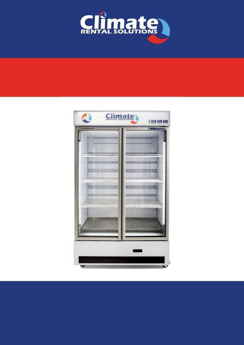
Climate RENTAL SOLUTIONS SK650 User manual

SK650
SINGLE DOOR FRIDGE
SAVE THESE INSTRUCTIONS FOR FUTURE REFERENCE
OPERATING MANUAL

OPERATING MANUAL SK650 SINGLE DOOR FRIDGE
Page 2
1. Cabinet and Refrigeration Unit
Cabinet Construction
Exterior/Interior: White powdercoat on galvanised steel
Insulation: 50mm thick, polyurethane foam Cyclo-iso Pentane blowing agent: C5H10/C5H12
Dimensions
Height: 2195mm
Width: 740mm
Depth: 700mm
Floor area: 0.52m2
Internal volume: 610 litres
Refrigeration Unit
SKOPE top mounted integral Cyclone® refrigeration unit:
Nominal capacity: 581 Watts
Compressor: Electrolux GLY90RA
Refrigerant: R134a / 450 grams
Electrical
230-240 Volts a.c. 50 Hz, single phase power supply
Run Amps: 2.77 Amps
Lighting
Single or twin sidelights: 35 Watt T5 uorescent tube (OSRAM FH 35W/860 Daylight) Ø16mm x 1450mm
Illuminated Sign
1 x 14 Watt T5 uorescent tube (OSRAM FH 14W/860 Daylight) Ø16mm x 550mm
Doors
Self-closing, aluminium framed, double glazed, toughened safety glass
Shelves
5 x adjustable height, white plastic coated, steel wire shelves
OPERATION
1. Safety Information
When using any electrical appliance, safety precautions should always be observed. Read these instructions carefully,
and retain for future reference.
• When used by, or near, young children or inrm persons, close supervision is necessary. Young children should
be supervised to ensure that they do not play with the appliance.
• Do NOT use this appliance for other than its intended use.
• Do NOT cover the grilles or block the entry or exhaust of airow by placing objects up against the refrigeration
unit.
SPECIFICATIONS

OPERATING MANUAL SK650 SINGLE DOOR FRIDGE
Page 3
• Do NOT probe any opening.
• Only use this appliance with voltage specied on the rating label.
• Ensure adequate ventilation of the SKOPE refrigeration unit.
• Be careful not to touch moving parts and hot surfaces.
• Regulations require that all electrical work be carried out by authorised persons. For your own safety, and that
of others, ensure this is done.
• If the supply cord becomes damaged, it must be replaced by a SKOPE authorised service agent, or similarly
qualied person, in order to avoid a hazard.
• If the refrigeration units are required to be installed or removed from the cabinet, ensure all necessary safety
precautions are observed.
Warning: Do NOT overload power supply.
Caution: Disconnect the cabinet from the mains power supply before attempting any cleaning or maintenance.
2. Operation of Machine
Plug in the cabinet and check operation of the refrigeration unit, electronic controller and cabinet lights.
Refrigeration unit
The compressor and evaporator and condenser fans should all operate initially. This may be veried by listening for
compressor switch on, and checking for air circulation inside the cabinet.
The compressor and condenser fan should switch o when the cabinet internal temperature reaches approximately
+2°C, and on again at approximately +4°C. The internal cabinet air will continue to circulate at all times.
Electronic controller
The electronic controller will either display the internal cabinet temperature or the controller set point. The compressor
‘on’ LED will indicate that the compressor is operating (see Figure 2 on page 12).
Cabinet lights
The lights which illuminate the top sign and cabinet interior are initially on, and will stay on permanently. The lighting
will require a period of time to stabilise following initial start up.
3. Loading
The shelves may be positioned at dierent heights to suit various products. Each shelf is held in place with four shelf
clips. Always ensure that the shelf clips are securely engaged in each of the four shelf support strips. The support
strips are marked with a ‘+’ for easy location of the shelf clips (see Figure 1 below).
When loading the shelves with product:
• ensure to allow air space around all packages etc, for even cooling and ecient operation.
• leave an airspace of at least 75mm (3”) above packages etc. on the top shelf.
• do not allow products to overhang the front of the shelf as this could prevent the door from shutting or cause
glass breakage.

OPERATING MANUAL SK650 SINGLE DOOR FRIDGE
Page 4
Figure 1: Shelf Clip
Shelf Support Strip
Shelf Clip
‘+’ Mark
Shelf
4. Cleaning
When necessary, wipe both interior and exterior of the cabinet with a damp cloth. Ensure the cabinet is disconnected
from the mains power supply before cleaning the cabinet.
Do not wipe the sealant o the door gasket, as the sealant ensures the door gasket forms a good seal with the
cabinet.
Periodic cleaning of the condenser coil is also recommended.
Condenser coil
The condenser coil MUST be kept clean for ecient and reliable operation. To ensure trouble free performance, it is
recommended that on a regular basis the cabinet be isolated from mains power supply and a vacuum cleaner used
to remove dust and u from the condenser coil.
The condenser coil should be brushed clean once a month, and blown clean by qualied service personnel, every six
months. The condenser coil is situated behind the sign unit. To access the condenser coil:
1. Disconnect the cabinet from the mains power supply.
2. Loosen the sign retaining clip on the top of each side panel.
3. Lift the sign unit up, to disengage from the sign sides.
4. Disconnect the sign ENSTO plug from the electrical box socket, and remove the sign unit from the cabinet.
Caution: Disconnect the cabinet from the mains power supply before cleaning the condenser coil.

OPERATING MANUAL SK650 SINGLE DOOR FRIDGE
Page 5
1. Controller Display
1
35
2
4
Figure 2: Controller Display
6
7
8
Item Key Function
1SET: Press to display target set point. In programming mode it selects a parameter or conrms an operation
2DEFROST: Press to start a manual defrost
3UP: Press to see the maximum stored temperature. In programming mode it browses the parameter codes, or
increases the displayed value
4DOWN: Press to see the minimum stored temp. In programming mode it browses the parameter codes, or decreases
displayed value
5 Compressor on LED indicator
6 Defrost cycle on LED indicator
7 Set Point displayed LED indicator
8 Decimal point LED indicator
Key Combinations:
+ Press both keys simultaneously, to lock and unlock the keypad
+ Press both keys simultaneously, to enter the programming mode
+ Press both keys simultaneously, to return to room temperature display
ELECTRONIC CONTROLLER

OPERATING MANUAL SK650 SINGLE DOOR FRIDGE
Page 6
Meaning of LEDs
Each LED function is described in the following table:
LED Mode Function
ON Compressor enabled
Flashing Anti-short cycle delay enabled
ON Defrost enabled
Flashing Drip time in progress
+Flashing Programming mode (see page 15)
ON The Set Point is displayed
2. Controller Operation
The SKOPE electronic controller controls and displays the cabinet temperature. The preset temperature setting
controls internal air temperature between 2°C and 4°C.
The electronic controller also signals and records temperature alarms, together with their duration and maximum
value reached (see Table 5 on page 18).
To ensure ecient operation, the electronic controller has a built in minimum o cycle time of 3 minutes and features
regular timed defrost cycles. During the defrost cycle, the compressor switches o and the evaporator fan stays on.
3. Programming Controller
The controller keypad must always be locked, to prevent unauthorised modication.
To unlock the keypad (to modify parameters)
Press both the UP and DOWN keys until ‘Pon’ is displayed.
How to lock the keypad
1. Press and hold both the UP and DOWN keys for more than 3 seconds.
2. The ‘PoF’ message will be displayed and the keypad will be locked. At this point it
will be possible only to see the Set Point or maximum or minimum temperature
stored.
3. If a key is pressed for more than 3 seconds, the ‘PoF’ message will be displayed.
To display the Set Point
Press, and immediately release the SET key. The display will show the Set Point value, and the Set

OPERATING MANUAL SK650 SINGLE DOOR FRIDGE
Page 7
Point LED will be highlighted.
To change the Set Point
1. Push and hold the SET key for more than 2 seconds.
2. The value of the Set Point will be displayed, and the LED will start
blinking.
3. To change the Set value, push the UP or DOWN keys.
4. To memorise the new Set Point value, push the SET key again or wait 15 seconds.
To start a manual defrost
Push and hold the DEFROST key for more than 2 seconds.
To change a parameter value
1. Enter the programming mode by pressing and holding both the
SET and DOWN keys for 3 sec. ( and start ashing).
2. Select the required parameter.
3. Press the SET key to display the Set value (now only the LED is ashing).
4. Press the UP or DOWN keys to change the Set value.
5. Press the SET key to store the new value and move to the following parameter.
6. To exit: Press both the SET and UP keys, or wait 15 seconds without pressing any keys.
7. To lock in new parameter value: after one minute operation, disconnect and reconnect cabinet into the mains
power supply.
NOTES:
1. The Set value is stored even when the procedure is exited by waiting for the time-out to expire.
2. Dependent on customer requirements, the SKOPE electronic controller has dierent parameter congurations.
Parameter conguration 160 = Beverage, 170 = Food, and 200 = Set Point display (see ‘Controller Parameters’
in Table 4 on page 17). To establish correct controller parameter conguration, see label on controller housing
(see Figure 3 on page 19).
To see the minimum temperature
1. Press and release the DOWN key.
2. The ‘Lt’ message will be displayed, followed by the minimum temperature.
3. Press the DOWN key again, or wait 5 seconds, to restore the normal display.

OPERATING MANUAL SK650 SINGLE DOOR FRIDGE
Page 8
To see the maximum temperature
1. Press and release the UP key.
2. The ‘Ht’ message will be displayed, followed by the maximum temperature recorded.
3. Press the UP key again, or wait 5 seconds, to restore the normal display.
To reset the maximum and minimum temperature
1. Press and hold the SET key for more than 3 seconds, while the maximum or minimum temperature is displayed.
The ‘rSt’ message will be displayed.
2. To conrm the operation, the ‘rSt’ message starts ashing and the normal temperature will be displayed.
3. Parameters
Display SKOPE Setting Min Max Description of Parameter
SET POINT PARAMETERS
Set 2 °C LS US Set Point
Hy 2 °C 0.1°C 25.5°C Dierential
LS -1 °C -50°C Set Minimum Set Point
US 15 °C Set 150°C Maximum Set Point
PROBE PARAMETERS
Ot 0.7 °C -12°C 12°C Thermostat probe calibration
OE 0 °C °C -12°C 12°C Condenser probe calibration
CONTROL PARAMETERS
OdS 0 Minutes 0 255 Outputs delay at start up
AC 3 Minutes 0 50 Anti-short cycle delay
DISPLAY PARAMETERS
CF °C °C / °F °C °F Temperature measurement unit
rES dE - in dE Resolution
LoD P1 - P1, P2 or SP Local display
DEFROST PARAMETERS
IdF 6 Hours 1 120 Interval between defrost cycles
MdF 12 Minutes 0 255 Maximum length for defrost
dFd dEF - rt, it Set, DEF Displaying during defrost
dAd 20 Minutes 0 255 Maximum display delay after defrost
ALARM PARAMETERS
ALc Ab - rE Ab Temperature alarms conguration
ALU 12 °C - 150°C Maximum temperature alarm
ALL -2 °C -50°C ALU Minimum temperature alarm
AtH 1 °C 0.1°C 25.5°C Dierential for temperature alarm in cabinet

OPERATING MANUAL SK650 SINGLE DOOR FRIDGE
Page 9
ALd 240 Minutes 0 255 Temperature alarm delay
dAO 24 - 0 Mins 23.5 Hours Delay of temperature alarm at start up
tbA n - n y Alarm relay silencing
PA2 58 °C -40°C AU2 Condenser over temperature
AU2 65 °C -40°C 110°C AUE Condenser alarm temperature
ACH 5 °C 0.1°C 25.5°C Dierential for condenser alarm temp recovery
dL2 2 Minutes 0 255 Condenser alarm delay
dA2 0 hh:mm 0 Mins 23.5 Hours Condenser alarm temperature delay at start up
AOP CL - OP CL Alarm relay polarity
OTHER PARAMETERS
dP1 - °C - - Thermostat probe read out
dP2 - °C - - Condenser probe read out
rEL - - - - Software release
Ptb - - - - Map code
4. Display Alarms
A ashing LED indicates an alarm. Possible alarm displays are:
Alarm Description
Stage ONE - Maintenance required:
Immediately attend condenser (for auto alarm reset).
Stage TWO - Refrigeration Shut-Down:
Condenser over-temperature has shut-down system and cabinet lighting. Attend condenser.
To reset alarm, cabinet must be replugged into power supply. For repeat alarms, contact an
authorised service agent.
Faulty Ambient probe (internal cabinet - return air)
Faulty High Temperature probe (condenser)
Internal cabinet - LOW temperature alarm
Internal cabinet - HIGH temperature alarm
Note: The refrigeration system and cabinet lighting shut down with ‘P1’, ‘P2’ and ‘CSd’ alarms.
Alarm Recovery
• Condenser over temperature alarm ‘COH’ recovers when the condenser is either cleaned or cools down.
• Condenser alarm ‘CSd’ temperature recovers by replugging the cabinet power supply (or isolation switch). In
this case, all the alarms are reset.
• Cabinet temperature alarms ‘LO’ and ‘HI’ automatically stop at temperature recovery.

OPERATING MANUAL SK650 SINGLE DOOR FRIDGE
Page 10
SERVICE INSTRUCTIONS
1. Troubleshooting
COMPLAINT POSSIBLE CAUSE REPAIR
1. Cabinet not operating - lights
etc not going.
Loss of power supply.
High pressure switch cut-out, due to over
heating.
Check power supply.
Check, and clean condenser. Check unit
operation, and reset pressure switch (see p.7).
2. Compressor will not start - no
hum.
Fuse removed or blown. No power.
Overload protector tripped.
Thermostat stuck in open position.
Thermostat o, due to cold location.
Wiring improper, or loose.
Replace fuse. Check reason.
Refer to electrical section.
Repair or replace control.
Relocate control.
Check wiring against diagram.
3. Compressor will not start -
hums but trips on overload
protector.
Improperly wired.
Low voltage to unit.
Start capacitor defective on CSIR or CSR motor.
Run capacitor defective on PSC motor.
Relay failing to close.
Compressor motor has a winding open or
shorted.
Internal mechanical trouble in com¬pressor.
Check wiring against diagram.
Determine reason and correct.
Determine reason and replace.
Determine reason and replace.
Determine reason and correct. Replace if
necessary.
Check resistance values. Replace compressor if
neces¬sary.
Replace compressor.
4. Compressor starts, but does
not switch o- startswinding.
Improperly wired.
Low voltage to unit.
Relay failing to open, due to welded contacts or
relay incorrectly mounted.
Run capacitor defective on CSR motor.
Excessively high discharge pres¬sure.
Compressor motor has winding open or shorted.
Check continuity and resistance.
Internal mechanical trouble in com¬pressor
(tight). May be lubrication.
Check wiring against diagram.
Determine reason and correct.
Determine reason and correct. Replace if
necessary.
Determine reason and replace.
Clean condenser. Check power input. Possible
overcharge, insucient condenser cooling, or
non-condensible gasses.
Replace compressor if faulty.
Replace compressor.
5. Compressor starts and runs,
butshort cycles on overload
protector (relay may chatter on
RSIR, CSIR and CSR motors).
Additional current passing through overload
protector.
Low voltage to unit.
Overload protector defective.
Run capacitor defective on CSR motor.
Excessive discharge pressure.
Suction pressure too high.
Compressor too hot - insucient suction gas
cooling.
Comp’r motor has a winding shorted.
Check wiring diagram. Check for added
fan motors etc., connected to wrong side of
protector.
Determine reason and correct.
Check current, replace protector.
Determine reason and replace.
Check condenser, check ventilation, check for
restrictions in refrigeration system.
Check for possibility of misapplication.
Check refrigerant charge (x leak), add if
necessary. Check return vapour temperature
and suction superheat.
Replace compressor.

OPERATING MANUAL SK650 SINGLE DOOR FRIDGE
Page 11
6. Unit runs OK, but short cycles.
Overload protector.
Thermostat: requires adjustment or incorrectly
positioned.
Incorrect refrigerant charge.
See section 4 on p.21.
Adjust or relocate thermostat.
Adjust refrigerant charge.
7. Unit operates long or continu-
ously.Unsatisfactory cabinet
tem¬perature.
Short of refrigerant.
Overcharge of refrigerant.
Thermostat not cooling correctly.
Freezer has excessive load.
Evaporator coil iced.
Restriction in refrigeration system.
Dirty condenser.
Inadequate air circulation.
Compressor not pumping eciently.
Filter dirty (if applicable).
Faulty fan motor.
Fix leak, and add charge.
Remove refrigerant to correct charge.
Adjust thermostat (clockwise colder), and check
thermostat bulb location. If necessary, replace
thermostat.
Establish load within limits.
Defrost evaporator, check refrigeration. Check
thermostat. Check door closing, seals etc.
Determine location and clear restriction.
Flush with dry nitrogen. Replace component if
blockage will not clear.
Clean condenser. Advise client how to regularly
clean condenser.
Internal: Improve air movement, alloe airow
around stock.External: Remove any restrictions
to condensing ventilation.
Replace compressor.
Clean or replace.
Check rotation. Replace if necessary.
8. Start capacitor open, shorted
or blown.
Relay contact not opening properly.
Prolonged operation on start cycle due to:(a)
Low voltage to unit.(b) Improper relay.
Excessive short cycling.
Improper capacitor.
Clean contacts, or replace relay if necessary.
(a) Determine reason and correct.(b) Replace
relay.
Determine reason for short cycling (see section
5 on p.21), and correct.
Determine correct size and replace.
9. Relay defective or burned out.
Incorrect relay.
Line voltage too high or too low.
Excessive short cycling.
Relay being inuenced by loose vibrating mount.
Check and replace.
Determine reason and correct.
Determine reason (see section 5 on p.21), and
correct.
Remount rigidly.
10. Suction line frosted. Evaporator fan not running.
Overcharge of refrigerant capillary systems.
Determine reason and correct.
Correct charge.
11. Unit noisy.
Loose parts or mountings.
Tubing rattle.
Bent fan blade causing vibration.
Fan motor bearing worn.
Find and tighten.
Reform to be free of contact.
Replace blade.
Replace motor.

Table of contents
Other Climate RENTAL SOLUTIONS Refrigerator manuals
Popular Refrigerator manuals by other brands

Beko
Beko nstallation & operating instructions and washing... operating instructions
Samsung
Samsung RF263TEAESR Features

Brandt
Brandt D3121X Operating and installation instructions

Zanussi
Zanussi ZXAK82FR user manual

Pkm
Pkm KS242-EM instruction manual

GE
GE Profile GSHS6LGZSS Dimensions and installation information
