ClimateMaster Tranquility TAC026BM17S Guide

Cased Coil for
Tranquility Split Series
Installation, Operation &
Maintenance Instructions
97B0100N01
Rev.: August 21, 2018
Tranquility Aluminum Tube Cased Coil (TAC)
Table of Contents
Model Nomenclature 3
General Information 4
Safety/Inspection 5
Specications 6
Dimensions 7
Installation 8 - 14
Maintenance 14
Warranty 15
RevisionHistory 16

This page was intentionally left blank.
3
Tranquility Aluminum Tube Cased Coil (TAC)
Rev.: August 21, 2018
climatemaster.com
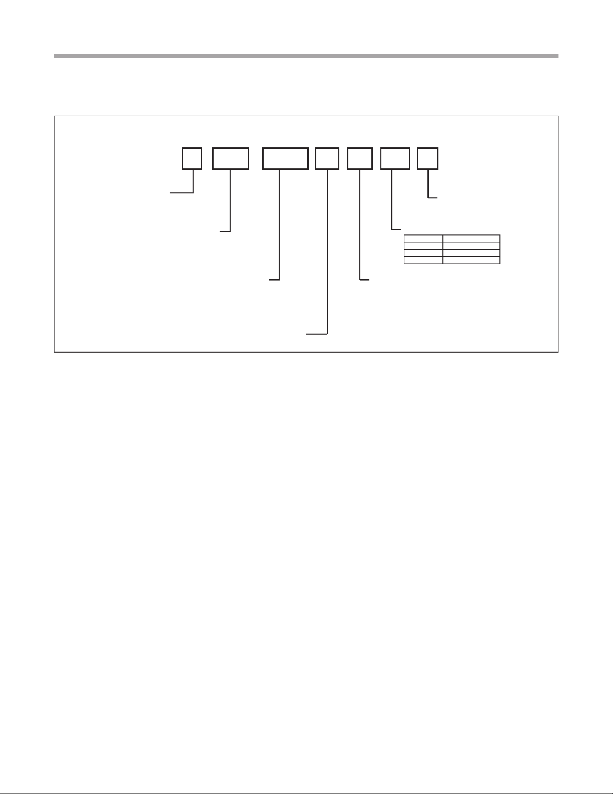
Model Nomenclature
ACT B026
2 31 4 5 6 7
T= TRANQUILITYHFC-410A
MODELTYPE
AC = CASED COIL
CONFIGURATION
026
NOMINALCAPACITY
038
049
REVISION LEVEL
064
M
8
COILOPTIONS
M = MULTI-POSITION CASED COIL
S
11
FUTURE USE
21
9 10
COILWIDTH
Width, Inches Nominal Capacity
17 26
21 26, 38, 49
24 38, 49, 64
B= CURRENT REVISION

Tranquility Aluminum Tube Cased Coil (TAC)
Rev.: August 21, 2018
4Geothermal Heating and Cooling
CASED COIL DESCRIPTION
ClimateMaster Tranquility Cased Coils are designed for
use with ClimateMaster indoor/outdoor split units and are
available for vertical upow or downow, and horizontal left
or horizontal right airow.
• Constructed of aluminum ns bonded to internally
grooved aluminum tubing.
• Coils are tested at the factory with an extensive
refrigerant leak check.
•Coils have sweat refrigerant connections.
•Ideally suited for new installations or add on air
conditioning.
•Feature two sets of 3/4” FPT condensate drain
connections for ease of connection.
• Coils are AHRI certied for system application with
ClimateMaster indoor and outdoor split units.
• Condensate drain pan is constructed of high grade, heat
resistant, corrosion free thermal-set material.
• Bi-Directional airow eliminates the need to switch any
internal components from horizontal left to right.
• Unique drain pan design maximizes application exibility
and condensate removal. � WARNING! �
WARNING! These instructions are intended as
an aid to qualied licensed service personnel for
proper installation, adjustment and operation of
this unit. Read these instructions thoroughly before
attempting installation or operation. Failure to follow
these instructions may result in improper installation,
adjustment, service or maintenance possibly resulting in
property damage, personal injury or death.
General Information
� CAUTION! �
� CAUTION! �
Inspection
Upon receipt of the equipment, carefully check the shipment
against the bill of lading. Make sure all units have been
received. Inspect the packaging of each unit, and inspect each
unit for damage. Insure that the carrier makes proper notation
of any shortages or damage on all copies of the freight bill and
completes a common carrier inspection report. Concealed
damage not discovered during unloading must be reported
to the carrier within 15 days of receipt of shipment. If not led
within 15 days, the freight company can deny the claim without
recourse. Note: It is the responsibility of the purchaser to le
all necessary claims with the carrier. Notify your equipment
supplier of all damage within fteen (15) days of shipment.
Storage
Equipment should be stored in its original packaging in a
clean, dry area. Store units in an upright position at all times.
Stack units a maximum of 3 units high.
Unit Protection
Cover units on the job site with either the original packaging
or an equivalent protective covering. Cap the open ends of
pipes stored on the job site. In areas where painting, plastering,
and/or spraying has not been completed, all due precautions
must be taken to avoid physical damage to the units and
contamination by foreign material. Physical damage and
contamination may prevent proper start-up and may result in
costly equipment clean-up.
Examine all pipes, ttings, and valves before installing any of
the system components. Remove any dirt or debris found in
or on these components.
Pre-Installation
Installation, Operation, and Maintenance instructions
are provided with each unit. Horizontal equipment is
designed for installation above false ceiling or in a ceiling
plenum. Other unit congurations are typically installed
in a mechanical room. The installation site chosen should
include adequate service clearance around the unit. Before
unit start-up, read all manuals and become familiar with the
unit and its operation. Thoroughly check the system before
operation.
Prepare units for installation as follows:
1. Compare the data on the unit nameplate with ordering
and shipping information to verify that the correct unit
has been shipped.
2. Keep the cabinet covered with the original packaging
until installation is complete and all plastering, painting,
etc. is nished.
3. Verify refrigerant tubing is free of kinks or dents and that
it does not touch other unit components.
CAUTION! CUT HAZARD - Failure to follow this caution
may result in personal injury. Sheet metal parts may have
sharp edges or burrs. Use care and wear appropriate
protective clothing, safety glasses and gloves when
handling parts and servicing.
CAUTION! DO NOT store or install units in corrosive
environments or in locations subject to temperature or
humidity extremes (e.g., attics, garages, rooftops, etc.).
Corrosive conditions and high temperature or humidity
can signicantly reduce performance, reliability, and
service life.

5
Tranquility Aluminum Tube Cased Coil (TAC)
Rev.: August 21, 2018
climatemaster.com
Safety
� WARNING! �
� CAUTION! �
CAUTION! It is recommended that an auxiliary secondary
drain pan be installed under units containing evaporator
coils that are located in any area of a structure where
damage to the building or building contents may occur as a
result of an overow of the coil drain pan or a stoppage in
the primary condensate drain piping.
The installation of water source heat pump units and all
associated components, parts and accessories which make
up the installation shall be in accordance with the regulations
of ALL authorities having jurisdiction and MUST conform to
all applicable codes. It is the responsibility of the installing
contractor to determine and comply with ALL applicable
codes and regulations.
Replacement Parts
Any replacement part must be the same as or an approved
alternate to the original part supplied. The manufacturer will
not be responsible for replacement parts not designed to
physically t or operate within the design parameters the
original parts were selected for. When ordering replacement
parts, it is necessary to order by part number and include
the complete model number and serial number from the coil
rating plate. (Parts are available through the local distributor.)
� WARNING! �
� WARNING! �
� CAUTION! �
CAUTION! To avoid equipment damage, DO NOT use
these units as a source of heating or cooling during the
construction process. The mechanical components and
lters can quickly become clogged with construction dirt
and debris, which may cause system damage and void
product warranty.
WARNING! To avoid the release of refrigerant into the
atmosphere, the refrigerant circuit of this unit must be
serviced only by technicians who meet local, state, and
federal prociency requirements.
WARNING! The EarthPure® Application and Service
Manual should be read and understood before attempting
to service refrigerant circuits with HFC-410A.
Safety
Warnings, cautions and notices appear throughout this
manual. Read these items carefully before attempting any
installation, service, or troubleshooting of the equipment.
DANGER: Indicates an immediate hazardous situation, which
if not avoided will result in death or serious injury. DANGER
labels on unit access panels must be observed.
WARNING: Indicates a potentially hazardous situation, which
if not avoided could result in death or serious injury.
CAUTION: Indicates a potentially hazardous situation or an
unsafe practice, which if not avoided could result in minor or
moderate injury or product or property damage.
NOTICE: Notication of installation, operation or maintenance
information, which is important, but which is not hazard-
related.
WARNING! PROPOSITION 65: This appliance contains
berglass insulation. Respirable particles of berglass
are known to the State of California to cause cancer.
All manufacturer products meet current Federal OSHA
Guidelines for safety. California Proposition 65 warnings
are required for certain products, which are not covered
by the OSHA standards. California’s Proposition 65
requires warnings for products sold in California that
contain or produce any of over 600 listed chemicals
known to the State of California to cause cancer or birth
defects such as berglass insulation, lead in brass,
and combustion products from natural gas. All “new
equipment” shipped for sale in California will have
labels stating that the product contains and/or produces
Proposition 65 chemicals. Although we have not changed
our processes, having the same label on all our products
facilitates manufacturing and shipping. We cannot always
know “when, or if” products will be sold in the California
market. You may receive inquiries from customers about
chemicals found in, or produced by, some of our heating
and air-conditioning equipment, or found in natural gas
used with some of our products. Listed below are those
chemicals and substances commonly associated with
similar equipment in our industry and other manufacturers.
• GlassWool (Fiberglass) Insulation
• Carbon Monoxide (CO).
• Formaldehyde
• Benzene
More details are available at the websites for OSHA
(Occupational Safety and Health Administration), at www.
osha.gov and the State of California’s OEHHA (Ofce
of Environmental Health Hazard Assessment), at www.
oehha.org. Consumer education is important since the
chemicals and substances on the list are found in our
daily lives. Most consumers are aware that products
present safety and health risks, when improperly used,
handled and maintained.
� WARNING! �
WARNING! This product can expose you to chemicals
including Carbon Black, which is known to the State of
California to cause cancer and Methanol, which is known
to the State of California to cause birth defects or other
reproductive harm. For more information go to
www.P65Warnings.ca.gov
The following warning complies with State of California law,
Proposition 65.

Tranquility Aluminum Tube Cased Coil (TAC)
Rev.: August 21, 2018
6Geothermal Heating and Cooling
Specifications
Table 1: Coil Specications/Airow Pressure Drop
Wet Coil Static Pressure Drop (Inches W.C.) - Coil Only
Coil Model
Face
Area
Ft2
(m2)
Case
Width
(cm)
600
CFM
700
CFM
800
CFM
900
CFM
1000
CFM
1100
CFM
1200
CFM
1300
CFM
1400
CFM
1500
CFM
1600
CFM
1700
CFM
1800
CFM
1900
CFM
TAC026BM17S 4.56
(0.42)
17.5
(44.5) 0.120 0.157 0.199 0.246
TAC026BM21S 5.70
(0.53)
21
(53.3)
0.113 0.145 0.181 0.222
TAC038BM21S 8.55
(0.79) 0.062 0.086 0.112 0.140 0.170 0.202 0.236 - - - - - - -
TAC038BM24S 8.55
(0.79) 0.062 0.086 0.112 0.140 0.170 0.202 0.202 0.272 0.309 - - - - -
TAC049BM21S 8.55
(0.79) 0.062 0.086 0.112 0.140 0.170 0.202 0.202 0.272 0.309 0.349 0.391 0.434 0.480 0.527
TAC049BM24S 8.55
(0.79) 24.5
(62.2)
0.062 0.086 0.112 0.140 0.170 0.202 0.202 0.272 0.309 0.349 0.391 0.434 0.480 -
TAC064BM24S 9.98
(0.93) 0.036 0.050 0.065 0.081 0.098 0.117 0.137 0.158 0.180 0.203 0.228 0.254 0.281 -
NOTE: Represents Coil-Only Airow Ratings

7
Tranquility Aluminum Tube Cased Coil (TAC)
Rev.: August 21, 2018
climatemaster.com
Table 2: Coil Dimensions and Weights
Dimensions
Figure 1: Dimensions
Model 026BM17 026BM21 038BM21 038BM24 049BM21 049BM24 064BM24
Connections - Sweat
Liquid I.D. - in 3/8 3/8 3/8 3/8 3/8 3/8 3/8
Suction I.D. - in 3/4 3/4 7/8 7/8 7/8 7/8 7/8
Cased Coil Dimensions
A - Width - in [cm] 17 1/2 [44.5] 21 [53.3] 21[53.3] 24 1/2 [62.2] 21 [53.3] 24 1/2 [62.2] 24 1/2 [62.2]
B - Coil Height - in [cm] 14 1/2 [36.8] 17 1/2 [44.5] 25 7/8 [65.7] 25 3/8 [64.5] 25 7/8 [65.7] 25 3/8 [64.5] 30 [76.2]
C- Height - in [cm] 20 [50.8] 20 [50.8] 28 [71.1] 32 [81.3] 28 [71.1] 32 [81.3] 32 [81.3]
Weight
Coil Weight lbs. [kg] 43 [20] 49 [22] 71 [32] 83 [38] 71 [32] 83 [38] 100 [45]
Shipping Weight lbs. [kg] 48 [22] 54 [24] 78 [35] 93 [42] 78 [35] 93 [42] 110 [50]
PRIMARY DRAIN
(VERTICAL
AND HORIZONTAL)
PRIMARY DRA NI
SUCTION LINE
LIQUID LINE
SECONDARY DRAIN NOTE: FLANGES ARE PROVIDED
FOR FIELD INSTALLATION
SECONDARY DRAIN
3/4" [19.1 mm] FPT
(HORIZONTAL)
Coil
Model
Number
Connections Cased Coil Dimensions Weight
Sweat (In. ) [mm] (In. ) [mm]
A B C
Coil Weight
(lbs. ) [Kg. ]
Shipping Weight
(lbs. ) [Kg. ]
Liquid I. D. Suction I. D.
2417 3/8 [9.53] 3/4 [19.05] 171⁄2[445] 177⁄8[454] 20 [508] 52 [24] 57 [26]
2421 3/8 [9.53] 3/4 [19.05] 21 [533] 171⁄2[445] 20 [508] 54 [24] 60 [27]
3624 3/8 [9.53] 7/8 [22.23] 241⁄2[622] 301⁄4[768] 32 [813] 108 [49] 118 [54]
4824 3/8 [9.53] 7/8 [22.23] 241⁄2[622] 301⁄4[768] 32 [813] 108 [49] 118 [54]
6024 3/8 [9.53] 7/8 [22.23] 241⁄2[622] 301⁄4[768] 32 [813] 108 [49] 118 [54]
DIMENSIONS AND WEIGHTS DATA
A MINUS ONE INCH
1/2"
CASING TOP AND BOTTOM OPENINGS
ARE THE SAME DIMENSIONS.
197/8”
7/16” [1.1 cm]
11/4” [3.2]
113/16”
53/8”
[13.7 cm]
21/4”
17/16”
515/16”41/8”
2111/16”
FRONT VIEW
SIDE VIEW
PLENUM WIDTH
[4.6 cm]
[5.7 cm]
[3.7 cm]
[15.1 cm][10.5 cm]
[55.1 cm]
[1.3 cm]
[50.5 cm]
[2.5 cm]
3/4" [19.1 mm] FPT
3/4" [19.1 mm] FPT
3/4" [19.1 mm] FPT
(VERTICAL)

Tranquility Aluminum Tube Cased Coil (TAC)
Rev.: August 21, 2018
8Geothermal Heating and Cooling
Installation
The Tranquility Cased Coils are designed for upow, horizon-
tal, and downow applications. The coils have a dry nitrogen
holding charge and are equipped with brazing stub refriger-
ant connections for easy installation.
The installer should read the installation manual supplied
with the compressor section for refrigerant line set sizing,
connection procedure, and other important information per-
taining to the system installation.
The installer should:
1. Make sure that the air delivery of the furnace is adequate
enough to handle the recommended CFM and allow for
pressure drop across the air coil, lter, and duct work.
2. Where precise forming of refrigerant lines is required, a
copper tubing bender is recommended for small diameter
tubing. One should avoid sharp bends and contact of the
refrigerant lines with metal surfaces.
3. Refrigerant lines should be protected where they pass
through the raw edges of holes.
4. Coil must be level or slightly pitched toward drain for
proper condensate drainage.
5. Seal the openings into the cabinet to reduce risk of con-
densate blow o from the coil.
The installer should:
1. Disconnect all electrical power to the furnace.
2. For the install of an cased coil, it might be necessary to
fabricate a plate to adapt the coil’s cabinet to the furnace
or air handler air discharge opening.
3. Install the cabinet and level or slightly pitch it as needed to
allow proper condensate drainage.
4. Seal the enclosure as required minimizing air leakage.
5. Connect the refrigerant lines as outlined in the Refrigerant
Lines section.
Cased Coil Installation
� WARNING! �
WARNING! Electric furnaces may be connected to
more than one supply circuit.

9
Tranquility Aluminum Tube Cased Coil (TAC)
Rev.: August 21, 2018
climatemaster.com
Applications
Tranquility Cased coils can be applied in upow, downow,
horizontal right and horizontal left applications without
modications. For horizontal applications, installation of an
auxiliary/secondary drain pan is required. For coils that are
two sizes larger than the furnace, for example, a 21” [53.3
cm] wide coil on a 14” [35.6 cm] furnace, a tapered adaptor
with a minimum height of 6” [15.2 cm] is required to evenly
distribute airow. See Figure 3. For coils that are one size
larger than the furnace; for example a 21” [53.3 cm] wide coil
on a 171⁄2” [44.5 cm] furnace, seal the gap between the two
units with sheet metal. See gure 4.
� CAUTION! �
CAUTION! For horizontal applications, the horizontal
drain pan must be located under the indoor coil. Failure
to place the pan under the coil can result in property
damage.
FIGURE 3
COIL INSTALLATION OPTIONS
HORIZONTAL RIGHT
UPFLOW
HORIZONTAL LEFT
AIRFLOW
AIRFLOW AIRFLOW
DOWNFLOW
AIRFLOW
PRESSURE
SENSITIVE
GASKET
IMPORTANT: Coil must be installed on the
supply airflow side of a gas or oil furnace.
Installation
Figure 2: Coil Installation Options
Coil
Model
Furnace Width [cm]
Oil* Gas
TAC-026 21 [53.3]
17 1⁄2 [44.5]
14 [35.6]
TAC-026 21 [53.3]
21 [53.3]
17 1⁄2 [44.5]
TAC-038
24 1⁄2 [62.2]
24 1⁄2 [62.2]
TAC-049
TAC-064 21 [53.3]
Table 3: Coil Application
*Due to the proximity of the drain pan to the high
temperature oil furnace drum, horizontal left application is
NOT permitted on oil furnaces.

Tranquility Aluminum Tube Cased Coil (TAC)
Rev.: August 21, 2018
10 Geothermal Heating and Cooling
Installation
FIGURE 4
INSTALLATION OF COIL MATCHED WITH A FURNACE TWO SIZES SMALLER
6" [15.2 cm]
MINIMUM
UPFLOW OR HORIZONTAL
LEFT APPLICATION
DOWNFLOW OR
HORIZONTAL
RIGHT APPLICATION
FIGURE 5
INSTALLATION OF COIL MATCHED WITH
A FURNACE OF SMALLER SIZE
When a cooling coil is matched with a gas fur-
nace of one smaller size, always center coil
over the furnace.
IMPORTANT: Seal the gap between the two
units with appropriate sheet metal parts.
Figure 3: Installation of coil matched with a furnace two sizes smaller
Figure 4: Installation of coil matched with a furnace of smaller size
FIGURE 4
INSTALLATION OF COIL MATCHED WITH A FURNACE TWO SIZES SMALLER
6" [15.2 cm]
MINIMUM
UPFLOW OR HORIZONTAL
LEFT APPLICATION
DOWNFLOW OR
HORIZONTAL
RIGHT APPLICATION
FIGURE 5
INSTALLATION OF COIL MATCHED WITH
A FURNACE OF SMALLER SIZE
When a cooling coil is matched with a gas fur-
nace of one smaller size, always center coil
over the furnace.
IMPORTANT: Seal the gap between the two
units with appropriate sheet metal parts.
Indicates airow
Indicates airow
Field fabricated
tapered adaptor

11
Tranquility Aluminum Tube Cased Coil (TAC)
Rev.: August 21, 2018
climatemaster.com
� CAUTION! �
CAUTION! Installation of a factory supplied liquid line
bi-directional lter drier is required. Never install a suction
line lter in the liquid line.
� CAUTION! �
See compressor section IOM for refrigerant charge
information.
Line Set Installation
Figure 9 illustrates a typical installation of an air handler or
cased coil matched to an indoor compressor section. Lineset
lengths should be kept to a minimum and should always be
installed with care to avoid kinking. Line sets are limited to 60
feet [18 meters] in length (one way). Line sets over 60 feet [18
meters] void the equipment warranty. If the line set is kinked or
distorted, and it cannot be formed back into its original shape,
the damaged portion of the line should be replaced. A restricted
line set will eect the performance of the system.
ClimateMaster Split units are shipped with a lter drier (loose)
inside the cabinet that must be installed in the liquid line at the
line set.
All brazing should be performed using nitrogen circulating
at 2-3 psi [13.8-20.7 kPa] to prevent oxidation inside the
tubing. All linesets should be insulated with a minimum
of 1/2” [13mm] thick closed cell insulation. All insulation
tubing should be sealed using a UV resistant paint or
covering to prevent deterioration from sunlight.
When passing refrigerant lines through a wall, seal
opening with silicon-based caulk. Avoid direct contact
with water pipes, duct work, oor joists, wall studs,
oors or other structural components that could transmit
compressor vibration. Do not suspend refrigerant tubing
from joists with rigid straps. Do not attach line set to the
wall. When necessary, use hanger straps with isolation
sleeves to minimize transmission of line set vibration to
the structure.
Installing the Lineset at the Compressor Section
Braze the line set to the service valve stubs as shown in Figure
5. Nitrogen should be circulated through the system at 2-3
psi [13.8-20.7 kPa] to prevent oxidation contamination. Use a
low silver phos-copper braze alloy on all brazed connections.
Compressor section is shipped with a factory charge.
Therefore, service valves should not be opened until the
line set has been leak tested, purged and evacuated.
Installation
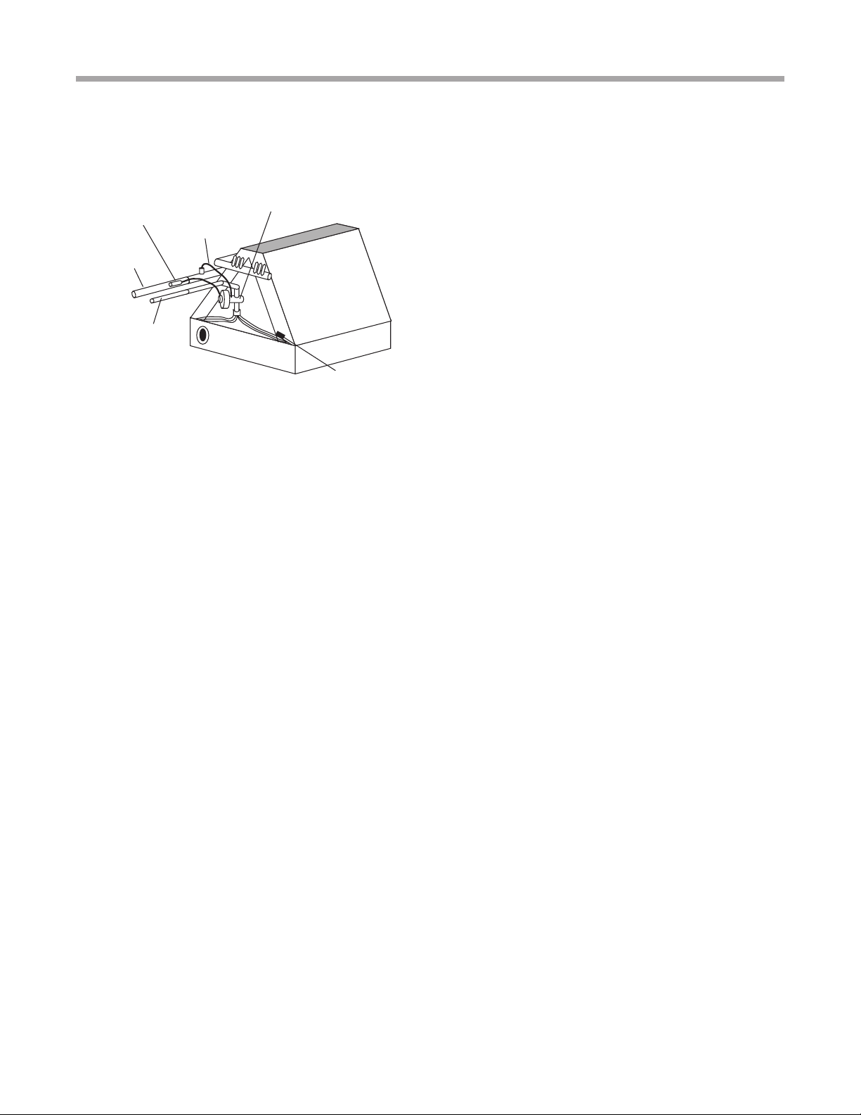
Installing the Indoor Coil and Lineset
Figure 6 shows the installation of the lineset and TXV to a
typical indoor coil. An indoor coil or air handler (fan coil) with a
TXV is required. Fasten the copper line set to the coil. Nitrogen
should be circulated through the system at 2-3 psi [13.8-20.7
kPa] to prevent oxidation inside the refrigerant tubing. Use a
low silver phos-copper braze alloy on all brazed connections.
Service ports for
gauges
CCW
CCW
service valves
Replace Caps after adjusting
service valves
Fully Insulated
Liquid Line
Fully Insulated
Vapor Line Nitrogen Braze
Figure 5: Braze Instructions
CAUTION! HFC-410A systems operate at higher
pressures than R-22 systems. Be certain that service
equipment (gauges, tools, etc.) is rated for HFC-410A.
Some R-22 service equipment may not be acceptable.
Fully Insulated
Vapor Line
Fully Insulated
Liquid Line
Nitrogen Braze
TES Compression Section
TEP Compression Section
Tranquility Aluminum Tube Cased Coil (TAC)
Rev.: August 21, 2018
12 Geothermal Heating and Cooling
Figure 6: Air Coil Connection
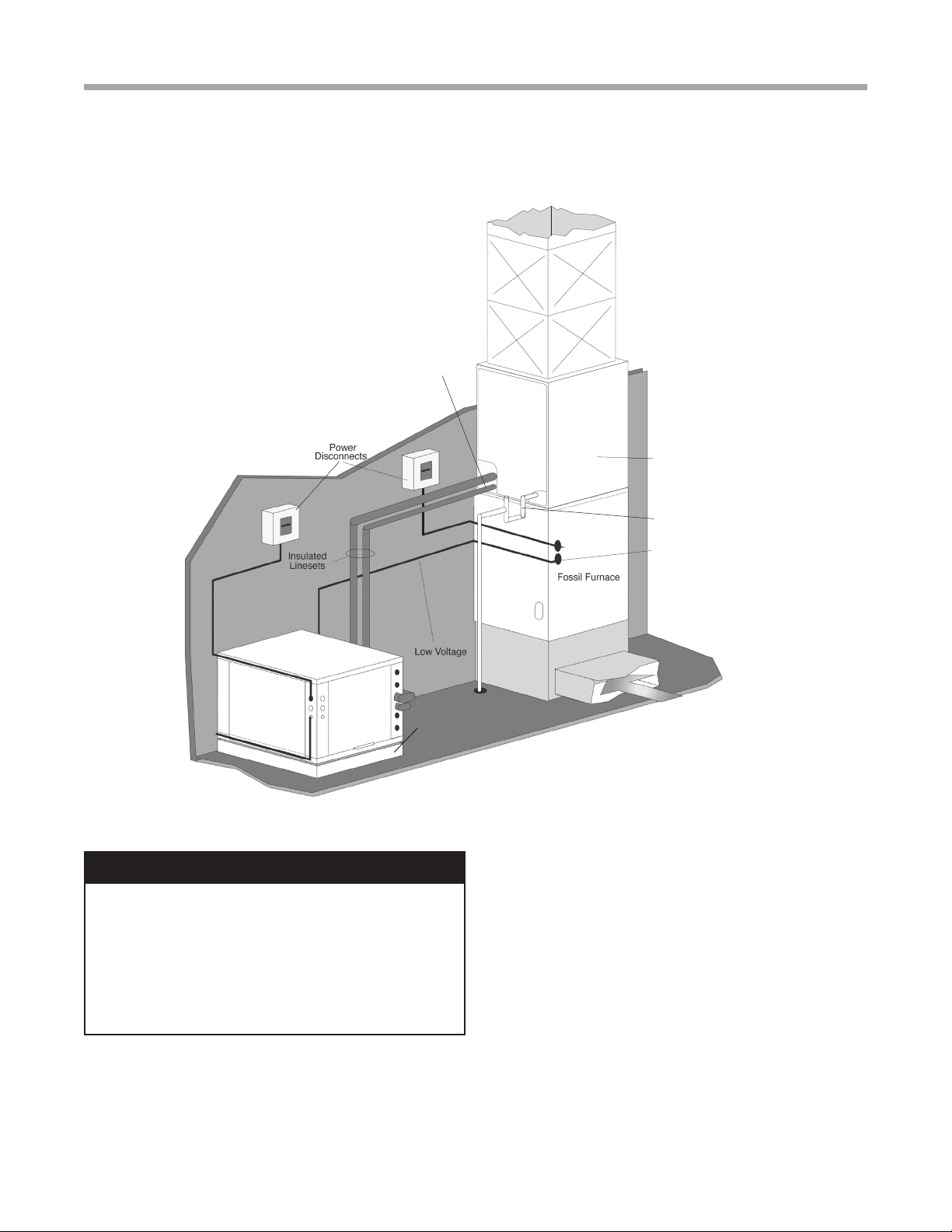
Add-On Heat Pump Applications
The indoor coil should be located on the supply side of
the furnace to avoid condensation damage to the furnace
heat exchanger for add-on heat pump applications. A high
temperature limit switch should be installed as shown
in Figure 9 just upstream of the coil to de-energize the
compressor any time the furnace is energized to avoid
blowing hot air directly into the coil, elevating refrigerant
pressures during operation. The heat pump will trip out on
high pressure lockout without some method of disengaging
the compressor during furnace operation. Alternatively, some
thermostats with “dual fuel” mode will automatically de-
energize the compressor when second stage (backup) heat
is required.
Air Coil
To obtain maximum performance of a newly manufactured
air coil it should be cleaned before start-up. A 10% solution
of dishwasher detergent and water is recommended for both
sides of the coil. A thorough water rinse should follow.
*An LT2 (low temperature air coil protection) sensor is
available for eld installation. Order sensor kit number
S17S0031N12.
Sensing Bulb
IMPORTANT: DO NOT perform any brazing with the TXV
bulb attached to any line. After brazing operations have been
completed, clamp the TXV bulb securely on the suction line
at the 10 to 2 o’clock position with the strap provided in the
parts bag. Insulate the TXV sensing bulb and suction line
with the provided pressure sensitive insulation and secure
with provided wire ties.
IMPORTANT: TXV sensing bulb should be located on a
horizontal section of copper suction line, just outside of
coil box. The copper sensing bulb must never be placed
on any aluminum tube as this will result in galvanic
corrosion and eventual failure of the aluminum tube.
Installation
Evacuation
LEAK TESTING -
The refrigeration line set must be pressurized
and checked for leaks before evacuating and charging the
unit. To pressurize the line set, attach refrigerant gauges to
the service ports and add an inert gas (nitrogen or dry carbon
dioxide) until pressure reaches 60-90 psig [413-620 kPa]. Never
use oxygen or acetylene to pressure test. Use a good quality
bubble solution to detect leaks on all connections made in the
eld. Check the service valve ports and stem for leaks. If a leak
is found, repair it and repeat the above steps. For safety reasons
do not pressurize system above 150 psig [1034 kPa]. System is
now ready for evacuation and charging.
Condensate Drain Tubing
Consult local codes or ordinances for specic requirements.
IMPORTANT: When making drain tting connections to the
drain pan, use a thin layer of Teon paste, silicone or Teon
tape and install hand tight.
IMPORTANT: When making drain tting connections to drain
pan, do not overtighten. Overtightening ttings can split pipe
connections on the drain pan.
•Install drain lines so they do not block service access
to front of the unit. Minimum clearance of 24 inches [61
cm] is recommended for lter, coil or blower removal and
service access.
• Make sure unit is level or pitched slightly toward primary
drain connection so that water will drain completely from
the pan. (See Figure 7.)
• Do not reduce drain line size less than connection size
provided on condensate drain pan.
• All drain lines must be pitched downward away from the
unit a minimum of 1/8” per foot [11 mm per m] of line to
ensure proper drainage.
• Do not connect condensate drain line to a closed or
open sewer pipe. Run condensate to an open drain or
outdoors.
• The drain line should be insulated where necessary to
prevent sweating and damage due to condensate forming
on the outside surface of the line.
TXV w/Internal
Check Valve
Suction Line
Liquid Line
Bulb (Must be
Installed and
Insulated)
Equalizer
Line
*LT2
Low Temperature
Air Coil Safety
(Optional)
13
Tranquility Aluminum Tube Cased Coil (TAC)
Rev.: August 21, 2018
climatemaster.com
Installation
• Make provisions for disconnecting and cleaning of the
primary drain line should it become necessary. Install
condensate trap at each unit with the top of the trap
positioned below the unit condensate drain connection
as shown in Figure 7. Design the depth of the trap
(water-seal) based upon the amount of ESP capability
of the blower (where 2 inches [51mm] of ESP capability
requires 2 inches [51mm] of trap depth). As a general
rule, 1-1/2 inch [38mm] trap depth is the minimum.
• Always vent the condensate line when dirt or air
can collect in the line or a long horizontal drain line
is required. Also vent when large units are working
against higher external static pressure than other units
connected to the same condensate main since this may
cause poor drainage for all units on the line. WHEN A
VENT IS INSTALLED IN THE DRAIN LINE, IT MUST
BE LOCATED AFTER THE TRAP IN THE DIRECTION
OF THE CONDENSATE FLOW.
• Auxiliary drain line should be run to a place where it will
be noticeable if it becomes operational. Occupant should
be warned that a problem exists if water should begin
running from the auxiliary drain line.
• Plug the unused drain connection with the plugs
provided in the parts bag, using a thin layer of Teon
paste, silicone or Teon tape to form a water tight seal.
• Test condensate drain pan and drain line after installation
is complete. Pour water into drain pan, enough to ll
drain trap and line. Check to make sure drain pan is
draining completely, no leaks are found in drain line
ttings, and water is draining from the termination of the
primary drain line.
Charging the System
See Compressor Section IOM for charging information.
� CAUTION! �
CAUTION! It is recommended that an auxiliary/secondary
drain pan be installed under units containing evaporator
coils that are located in any area of a structure where
damage to the building or building contents may occur as
a result of an overow of the coil drain pan or a stoppage
in the primary condensate drain piping.
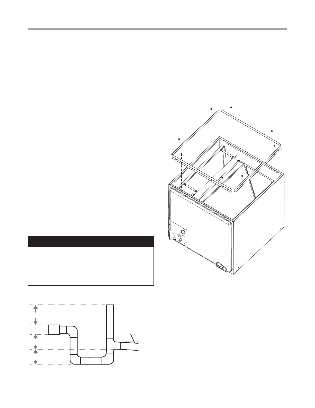
FIGURE 7
FIELD-INSTALLED DUCT FLANGES
Figure 7: Condensate drain trap/vent
Figure 8: Field-installed duct anges
Duct Flanges
Field-installed duct anges (4 pieces) are shipped with units.
Install duct anges as needed on top or bottom of the coil
casing. (See Figure 8.)
2”
1.5”
1.5”
1/8” Per
Foot
UNIT MUST BE LEVEL OR SLIGHTLY
PITCHED TOWARD DRAIN CONNECTION
[5 cm]
[3.8 cm]
[3.8 cm]
[11mm per m]
Tranquility Aluminum Tube Cased Coil (TAC)
Rev.: August 21, 2018
14 Geothermal Heating and Cooling
Figure 9: Typical Split/Add-on Coil Fossil Fuel Furnace Installation
TAC
Cased Coil
Low Voltage
Compressor Section
PVC Condensate
with vented trap
Air pad or Extruded
polystyrene
Air Temperature
Limit Switch
Installation
� WARNING! �
WARNING! These instructions are intended as
an aid to qualied licensed service personnel for
proper installation, adjustment and operation of
this unit. Read these instructions thoroughly before
attempting installation or operation. Failure to follow
these instructions may result in improper installation,
adjustment, service or maintenance possibly resulting in
property damage, personal injury or death.
For continuing high performance and to minimize possible
equipment failure, it is essential that annual maintenance be
performed on this equipment. Consult your local dealer
as to the availability of a maintenance contract.
Air Filter
Check the system lter every ninety days or as often as found
to be necessary and if obstructed, clean or replace at once.
IMPORTANT: Do not operate the system without a lter in
place.
Indoor Coil - Drain Pipe - Drain Line
Inspect the indoor coil once each year for cleanliness and
clean as necessary. In some cases, it may be necessary to
remove the lter and check the return side of the coil with
a mirror and ashlight.
IMPORTANT: Do not use caustic household drain cleaners
or bleach in the condensate pan or near the indoor coil.
Drain cleaners will quickly damage the indoor coil.
MAINTENANCE
15
Tranquility Aluminum Tube Cased Coil (TAC)
Rev.: August 21, 2018
climatemaster.com
Warranty
CLIMATE MASTER, INC.
LIMITED EXPRESS WARRANTY AND LIMITATION OF LIABILITY AND
REMEDIES FOR RESIDENTIAL CLASS PRODUCTS WITH LABOR ALLOWANCE
This Limited Express Warranty And Limitation Of Liability And Remedies Affects Your Legal Rights And Should Be Read Carefully In Its Entirety.
Subject to the terms and conditions below, Climate Master, Inc. (“CM”) extends a limited warranty (“Limited Warranty”) for Residential Class heating and cooling equipment manufactured or sold by CM (“Products”), that was purchased on or after May 1, 2010 (this would generally include
CM Units with serial numbers beginning with “N118” and higher), and installed in a one or two family residential dwelling, for personal, household or family purposes in the United States of America or Canada, (“Application”), to be free from defects and workmanship under normal use and
maintenance. If you are unsure if this Limited Warranty applies to a Product you have purchased, contact CM at the phone number or address reected below.
This Limited Warranty DOES NOT cover commercial applications of the Products. Commercial applications include any application other than installation in a one or two family residential dwelling for personal, household or family purposes. Refer to ClimateMaster Commercial Limited Express
Warranty for details. Full copies are available for download at ClimateMaster.com .
This Limited Warranty provides a complete statement of CM’s responsibilities to purchasers of the Products. No oral or written statement made by CM, any person or entity associated with CM or by any person or entity claiming to be associated with CM, including but not limited to statements
made in sales literature, catalogs, or agreements to purchase or install the Products, is intended to provide an express or implied warranty of any kind and does not form a part of the basis of the bargain. Further, no such statement shall operate to extend, alter or modify the scope or terms of this
Limited Warranty.
EXCEPT AS SPECIFICALLY SET FORTH HEREIN, THERE IS NO EXPRESS WARRANTY AS TO ANY OF CM’S PRODUCTS. CM MAKES NO WARRANTY AGAINST LATENT DEFECTS, OF MERCHANTABILITY OF THE PRODUCTS OR OF THE PRODUCTS
FOR ANY PARTICULAR PURPOSE.
TERM: This Limited Warranty shall commence on the earliest to occur of the following dates: (i) proof of date of rst occupancy; (ii) proof of date of start-up of the Product by a qualied and trained HVAC contractor; or (iii) six (6) months from the shipment date of the Product from CM if items
(i) or (ii) are not available (“Warranty Inception Date”). The Limited Warranty shall extend as follows:
Costs of Repair or Replacement of Covered Product Parts
(1) Ten (10) years from the Warranty Inception date for air conditioning, heating and/or heat pump units built or sold by CM (“CM Units”);
(2) Ten (10) years from the Warranty Inception Date for thermostats, auxiliary electric heaters, water storage tanks, and geothermal pumping modules built or sold by CM, when installed with CM Units;
(3) One (1) year from the date of shipment from CM for any other accessories or parts built or sold by CM, when installed with CM Units; and
(4) Ninety (90) days from the date of shipment from CM for all repair or replacement parts that are not supplied under this warranty.
Costs of Labor to Install Repaired or Replaced Covered Product Parts
(1) Five (5) years from the Warranty Inception Date for CM Units;
(2) Five years from the Warranty Inception Date for thermostats, auxiliary electric heaters, water storage tanks, and geothermal pumping modules built or sold by CM, when installed with CM Units
This Limited Warranty does not cover labor costs for installation of other accessories or parts built or sold by CM or any repaired or replacement parts that are not supplied under this Limited Warranty.
WHO IS COVERED: This Limited Warranty is provided only to the original owner of the one or two family residential dwelling in which the Products are rst installed. This Limited Warranty is not transferrable. CM reserves the right to request any documentation necessary in its sole discretion
to determine the date of purchase and occupancy of the residential dwelling or the date of installation and start-up of the Product(s). For the avoidance of any doubt, this Limited Warranty shall not extend to, and shall provide no remedies whatsoever for, any distributor or installer of the Products.
CLAIM PROCESS: To make a claim under this warranty, the Product or parts must be returned to CM in Oklahoma City, Oklahoma, freight prepaid, no later than ninety (90) days after the date of the failure of the part. If CM determines the Product or part to be defective and covered by this
Limited Warranty, CM will either repair or replace the Product or part and send it to a CM-recognized distributor, dealer or service organization, F.O.B. CM, Oklahoma City, Oklahoma, freight prepaid. The Limited Warranty on any Product or part repaired or replaced under this Limited Warranty
extends only through the original warranty period.
WHAT IS COVERED: Subject to the Term, this Limited Express Warranty covers the: (i) the cost of repair or replacement of any covered Product or Product parts; and (ii) the cost of labor incurred by CM authorized service personnel in connection with the installation of a repaired or replaced
covered Product or Product part.
If a Product part is not available, CM will, at its option, provide a free suitable substitute part or provide a credit in the amount of the then factory selling price for a new suitable substitute part to be used by the claimant towards the retail purchase price of a new CM product. All labor costs are
subject and limited to amounts specically set forth in the then existing labor allowance\ schedule provided by CM’s Warranty Department. Actual labor costs are not covered by this Limited Warranty to the extent they: (i) exceed the amount allowed under the allowance schedule; (ii) are not
specically provided for in the allowance schedule; (iii) are not performed by CM authorized service personnel; (iv) are incurred in connection installation of a part not covered by this Limited Warranty; or (v) are incurred outside the Term.
WHAT IS NOT COVERED: This Limited Warranty does not cover and does not apply to: (1) air lters, fuses, refrigerant, uids, oil; (2) Products relocated after initial installation; (3) any portion or component of any system that is not supplied by CM, regardless of the cause of the failure of
such portion or component; (4) Products on which the unit identication tags or labels, or rating labels, have been removed or defaced; (5) Products on which payment to CM, or to the owner’s seller or installing contractor, is in default; (6) Products which have not been installed and maintained by
a qualied and trained HVAC contractor; (7) Products installed in violation of applicable building codes or regulations including but not limited to wiring or voltage conditions; (8) Products subjected to accident, misuse, negligence, abuse, re, ood, freezing, lightning, unauthorized alteration,
misapplication, contaminated or corrosive air or liquid supply, operation at abnormal air or liquid temperatures or ow rates, or opening of the refrigerant circuit by unqualied personnel; (9) mold, fungus or bacteria damages; (10) corrosion or abrasion of the Product; (11) products supplied by
others; (12) Products that have been operated in a manner contrary to CM’s printed instructions; (13) Products which have insufcient performance as a result of improper system design, sizing or the improper application, installation, or use of CM’s products; (14) electricity or fuel costs, or any
increases or unrealized savings in same, for any reason whatsoever; or (15) operating any water storage tanks when they are empty or partially empty (i.e. dry ring), at temperatures exceeding the maximum setting of the operating or high limit controls, at pressures greater than those shown on the
rating label, with non-potable water, with alterations or attachments (including energy savings devises) not specically authorized in writing by CM, or without the free circulation of water. CM may request written documentation showing compliance with the above limitations.
In connection with repair or replacement of covered Product parts, CM is not responsible for: (1) the costs of any uids, refrigerant or system components supplied by others, or associated labor to repair or replace the same, which is incurred as a result of repair or replacement of a covered Product
part; (2) the costs of labor, refrigerant, materials or service incurred in diagnosis and removal of a covered Product part subject to repair or replacement under this Limited Warranty; (3) shipping costs incurred in sending a claimed defective part from the installation site to CM; (4) shipping costs to
return a claimed defective part from CM to the installation site if the part is not covered by this Limited Warranty; (5) removal or disposal costs associated with the repair or replacement of covered Product Parts; or (6) the costs of normal maintenance.
OTHER WARRANTY LIMITATION: This Limited Warranty is given in lieu of all other warranties express or implied, in law or in fact. If, notwithstanding the disclaimers contained herein, it is determined that other warranties apply, any such warranty, including without limitation any express
warranties or any implied warranties of tness for particular purpose and merchantability, shall be limited in time to the Term of this Limited Warranty
LIMITATION OF REMEDIES: In the event of a breach of the Limited Warranty, a claimant’s remedies will be limited to repair or replacement of a part or unit, or to furnish a new or rebuilt part or unit in exchange for the part or unit which has failed. If after written notice to CM’s factory
in Oklahoma City, Oklahoma of each defect, malfunction or other failure, and a reasonable number of attempts by CM to correct the defect, malfunction or other failure, the remedy fails of its essential purpose, CM shall refund the purchase price paid to CM in exchange for the return of the
sold good(s). Said refund shall be the maximum liability of CM. THIS REMEDY IS THE SOLE AND EXCLUSIVE REMEDY OF THE BUYER OR THEIR PURCHASER AGAINST CM FOR ANY ACTION FOR BREACH OF CONTRACT, BREACH OF ANY WARRANTY, PATENT
INFRINGEMENT, OR FOR CM’S NEGLIGENCE OR IN STRICT LIABILITY. NO ACTION ARISING OUT OF ANY CLAIMED BREACH OF THIS LIMITED WARRANTY MAY BE BROUGHT MORE THAN ONE (1) YEAR AFTER THE CAUSE OF ACTION HAS ARISEN.
LIMITATION OF LIABILITY: CM shall have no liability for any damages if CM’s performance is delayed for any reason or is prevented to any extent by any event such as, but not limited to: any war, civil unrest, government restrictions or restraints, strikes, or work stoppages, re, ood,
accident, shortages of transportation, fuel, material, or labor, acts of God or any other reason beyond the sole control of CM.
CM EXPRESSLY DISCLAIMS AND EXCLUDES ANY LIABILITY FOR CONSEQUENTIAL, INCIDENTAL, SPECIAL AND/OR PUNITIVE DAMAGES BASED ON ANY THEORY IN CONTRACT, BREACH OF ANY EXPRESS OR IMPLIED WARRANTY, PATENT
INFRINGEMENT, OR IN TORT, WHETHER FOR CM’s NEGLIGENCE OR AS STRICT LIABILITY AND REGARDLESS OF WHETHER CM IS ADVISED OF THE POSSIBILITY OF SUCH DAMAGES.
OBTAINING WARRANTY PERFORMANCE: Normally, the dealer or service organization who installed the products will provide warranty performance for the owner. Should the installer be unavailable, contact any CM recognized distributor, dealer or service organization. If assistance is
required in obtaining warranty performance, write or call:
Climate Master, Inc. • Customer Service • 7300 SW 44th Street • Oklahoma City, Oklahoma 73179 • (405) 745-6000 • e-service@climatemaster.com
NOTE: Some states or Canadian provinces do not allow the exclusion or limitation of implied warranties or the limitation of incidental or consequential damages for certain products supplied to consumers, or the limitation of liability for personal injury, so the above limitations and exclusions
may be limited in their application to you. When the implied warranties are not allowed to be excluded in their entirety, they will be limited to the duration of the applicable written warranty. This warranty gives you specic legal rights, which may vary depending on local law. IF ANY PRODUCT
TO WHICH THIS LIMITED WARRANTY APPLIES IS DETERMINED TO BE A “CONSUMER PRODUCT” UNDER THE MAGNUSON-MOSS WARRANTY ACT (15 U.S.C.A. §2301, ET SEQ.) OR OTHER APPLICABLE LAW, THE FOREGOING DISCLAIMER OF IMPLIED
WARRANTIES SHALL NOT APPLY TO YOU, AND ALL IMPLIED WARRANTIES ON THIS PRODUCT, INCLUDING WARRANTIES OF MERCHANTABILITY AND FITNESS FOR THE PARTICULAR PURPOSE, SHALL APPLY FOR THE SAME TERM SET FORTH ABOVE
(ONE YEAR) AS PROVIDED UNDER APPLICABLE LAW. The portions of this Limited Warranty and limitation of liability shall be considered fully severable, and all portions which are not disallowed by applicable law shall remain in full force and effect.
This warranty gives you specic legal rights, and you may also have other rights which vary from state to state and from Canadian province to Canadian province. Refer to your local laws for your specic rights under this Limited Warranty.
Please refer to the CM Installation, Operation and Maintenance Manual for operating and maintenance instructions.
Rev.: 3/20
Part No.: RP851
Tranquility Aluminum Tube Cased Coil (TAC)
Rev.: August 21, 2018
16 Geothermal Heating and Cooling
Revision History
97B0100N01
ClimateMaster works continually to improve its products. As a result, the design and specications of each product at the time for order may be
changed without notice and may not be as described herein. Please contact ClimateMaster’s Customer Service Department at 1-405-745-6000
for specic information on the current design and specications. Statements and other information contained herein are not express warranties
and do not form the basis of any bargain between the parties, but are merely ClimateMaster’s opinion or commendation of its products.
© ClimateMaster, Inc. 2010
*97B0100N01*
7300 S.W. 44th Street
Oklahoma City, OK 73179
Phone: 405-745-6000
Fax: 405-745-6058
climatemaster.com
Date Page # Description
August 21, 2018 4 Added warning
November 5, 2015 All Updated to Aluminum Tube
April 23, 2012 3, 7 TAC 026-B Dimensions Corrected
July 6, 2011 3 Decoder Updated
April 22, 2010 All First Published
This manual suits for next models
6
Table of contents
Other ClimateMaster Air Conditioner manuals


Popular Air Conditioner manuals by other brands

Webasto
Webasto Frigo Top 25 DS Instructions for use

Daikin
Daikin Split Sensira R32 Service manual

Samsung
Samsung AM***FN*D series user manual

Mitsubishi Electric
Mitsubishi Electric Mr. Slim PUZ-M200YKA2.UK Service manual

Panasonic
Panasonic CU-E9GFE-2 operating instructions

Airwell
Airwell AW-CFM012-N11 Service manual


 Operation manual")


