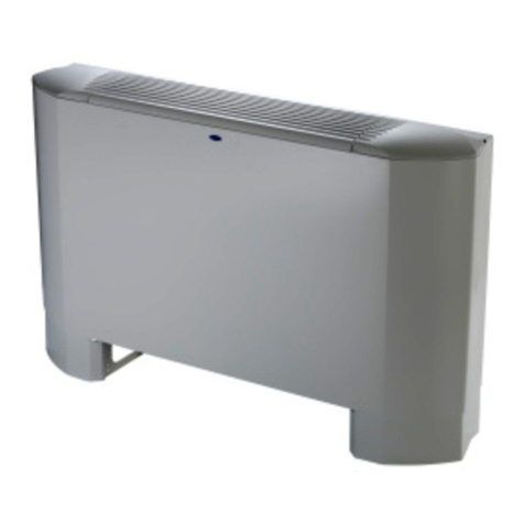
Climma Compact Series User manual

COMPACT & SPLIT - QUATTRO
INSTALLATION MANUAL
Climma Compact Units
Cod. A52040NA Aug 2011

AIR-CONDITIONERS
Page www.veco-na.com
2.1 Installation diagram of the Compact air-conditioner
04) Electrical box
05) Electrical supply
06) Return air grille
07) Air filter
08) Remote control panel
09) Flexible duct
10)Transition
11) Discharge grille
12) Condensation drain hose
13) Sea water inlet hose
14) Sea water pump
15) Sea water ball valve (shown closed)
16) Sea water strainer
17) Scoop thru-hull intake
18) Air intake
19) Air-conditioner unit
20) Sea water discharge
08
17
16
15 14
13
12
06
11
10
04
18 09
07
19
20
05

AIR-CONDITIONERS
Page www.veco-na.com
3 INSTALLATION OF THE COMPONENTS
3.1 - FUNCTION OF AN AIR-CONDITIONER
During the cooling cycle, the refrigerant circuit takes heat from
the ambient air and transfers it to the sea water. Whilst doing so, it will
also dehumidify and filter the air.
In the reverse-cycle mode the opposite takes place, and heat is removed
from the sea water and transfered to the air in the cabin
Choosing the unit position, it is necessary to consider the following elements:
1 - the accessibility to the air filter for cleaning;
2 - the necessary space for the fastening of the securing clips;
3 - the connection of the condensation drains;
4 - the connection of the duct to the duct ring on the unit;
5 - the connection of the sea water circuit pipes;
6 - the intended location of the electrical box.
3.2 - ARRANGEMENT - General notes
Typical one-outlet installation

AIR-CONDITIONERS
Page www.veco-na.com
C - The return air grille should be located so that
there is unobstructed air space between it and
the air intake on the unit, as in picture 1.6.
D - Alternatively, the unit may be reversed, as in
picture 2.6.
3.3 - Unit Location
A.- The unit must be
located in the area to be
conditioned. Typical
locations are under a
setee or bunk. A Compact
unit must never be located
in an engine space.
B.- The conditioned air must be ducted to one or more grills through ducts of suitable size,
either insulated or non-insulated.
View from above
Figure 1.6
Figure 2.6
View from above
3 INSTALLATION OF THE COMPONENTS

AIR-CONDITIONERS
Page www.YHFRQDFRP
3.4- FASTENING
The Compact unit should be secured by the clips.
.
3.5- CONDENSATE DRAIN
The Climma Compact unit will extract a significant quantity
of moisture from the air, and this must be disposed of by
means of a gravity condensate drain. This drain can either
be to the bilge or to a sump with float-switch and pump.
The condensate drain
fittings provided are for
5/8" ID hose.
Do not use smaller diametermm on the
hose.
.
Each unit is equipped with two out-
lets, as you can see in the picture
above.Either one or both drains may be used.
Condensate drains should ideally make a vertical
orientation as soon as possible after the pan fitting.
If both drains are to be used, they should be joined
together at a point lower than the drain pan.
Do not make more than one "U" trap in the condensatebe
drain as this can lead to a pneumatic lock that will
prevent the drain from functioning.
DO NOT lead condensate drain directly overboard.
This can lead to the ingress of potentially lethal fumes
from exhaust emissions, etc.
5efer to the safety regulations UHOHYDQWWR\RXU
JHRJUDSKLFDODUHD
NEOPRENE
3 INSTALLATION OF THE COMPONENTS
Figure 1.8
Dis 2.8
Figure 2.8

AIR-CONDITIONERS
Page www.YHFRQDFRP
Check the efficiency
of the condensate
drain by pouring some
water into the pan.
3.7- AIR FILTER
The Air Filter is mounted on the Compact unit in front of the air intake, and is essential for trapping dust and lint
that would otherwise clog the fins on the air intake. The Air Filter should be checked and cleaned periodically,
more often with high-usage units and on vessels with an abundance of carpets and rugs and with pets on board.
3.6- CONDENSATE DRAIN
When the blower is operating, the area
surrounding the Compact unit becomes
a low pressure area. A trap in the drain
(Fig. A) will prevent odours from being
sucked up and entering the ducting system.
3 INSTALLATION OF THE COMPONENTS
A
A
Figure 1.9
Sump

AIR-CONDITIONERS
Page www.veco-na.com
3 INSTALLATION OF THE COMPONENTS
3.8- AIR CIRCULATION SYSTEM (see examples on page 11)
3.8.A - Return Air
The cabin air returns to the Compact unit through a
return air grille of appropriate dimensions.
(Minimum return air grille sizing for Compact units
is shown on the Compact spec sheet).
See spec sheet
3.9- Ducting
When using flexible duct, ensure that the
duct maintains its diameter and is not crushed
when passing through bulkheads and around
tight corners.
3.10- Air ducts
Stretch flexible ducts so that the maximum
internal diameter is maintained. Cut duct to
correct length, and do not 'concertina' duct
which will reduce the internal diameter.
.
View from above
Viiew from above

AIR-CONDITIONERS
Page www.YHFRQDFRP
3 INSTALLATION OF THE COMPONENTS
3.11- Duct Connections
The collar on the blower discharge corresponds to the
minimum size of duct allowable.
Do not attempt to connect a duct of smaller diameter
than the duct collar on the Compact unit.
The blower can be rotated 90° for installationswith limited height.
Example of a Compact installation using a "T" or "Y" to split the duct to two or more
discharge grilles. The main grille must be of minimum area for size of unit (see
Compact spec sheet) and non-closeable. Secondary grilles can be closeable.

AIR-CONDITIONERS
Page www.veco-na.com
4 SEA WATER CIRCUIT
4.1 - SEA WATER PUMP
The sea water pump must be of the correct size for the Compact unit.
Most installations require a centrifugal pump, and close attention to
the installation requirements must be made to ensure trouble-free
operation.
Centrifugal pumps are not self-priming and MUST be mounted with the
discharge below the waterline, with a rising hose run through the strainer
and on to the pump, and with a scoop intake strainer facing towards
the bow of the vessel.
4.2 - LOCATION
4.2 - A 4.2 - B
4.2 - C 4.2 - D
Install the sea water pump so that its outlet is vertical,
and as far below the water line as possible.Scoop intake strainer must point towards the bow.
The hose must make a continual rise from the ball valve,
through the strainer, and into the pump inlet. All items in
the pump circuit must be as far below the water line as
possible. Use wire-reinforced hose for this section, and
secure hoses using double stainless steel hose clamps
of high quality.
The hose runs from the ball valve to the inlet of the pump,
via the strainer should be as short as possible.
4.3 - SECURING
Secure the pump using screws or bolts. Use
anti-vibration dampers if provided with pump.
.
STERN BOW
MAX 1 mt
NOTE: The restrictions here do not
apply to DC or AC diaphragm pumps.
These can be mounted above the
waterline and share an inlet.

AIR-CONDITIONERS
Page 1www.veco-na.com
4 SEA WATER CIRCUIT
4.4- SEA WATER CIRCUIT
The water intake and discharge ports on the Compact unit
are marked with arrows. Correct water flow direction is important.
for efficient performance of the Compact unit.
.
Connections may
differ from those
shown
Min 2"

AIR CONDITIONERS
Page 1www.veco-na.com
5 ELECTRICAL CIRCUIT
AVOID THE RISK OF THE ELECTROCUTION !!!
Only qualified persons should attempt installation, troubleshooting, and repair.
Ensure that power to the system is disconnected before removing covers to electrical boxes.
IMPORTANT NOTE
To avoid possible electrical shocks that may cause injury or death, the Compact unit must be properly connected
to a safety ground, as follows:
1- Use a correctly sized 3-conductor electrical cable with ground wire section and isolation.
2- Use only marine grade cable with multi-strand tinned conductors. Do not use residential wire with solid conductors
3- The ground wire must be correctly connected to the ground terminal of the panel.
4- Check that the ground connection between the electrical box and the air-conditioner has not suffered from
damage during transport.
5- Check that the ground connection of the water pump is securely and properly connected in the electrical box.
6- Check the ground continuity with a multi-meter before switching off the air-conditioner.
WARNING
5.1 - Vega II, Vega III, and FX II Controls
All electrical connections are made inside the Power Module box. See control Manuals for specific details.
5.2 - SUPPLY
Check that the available supply corresponds to the label on the unit, on the box and on the electrical pump.
Power should be supplied from a breaker of the correct rating. See spec sheet for details.
All electrical wiring must be marine grade, of the correct gage, and with multi-strand tinned conductors.
All connections on the terminal strips must be made with correctly sized wire and/or connectors.
5 ELECTRICAL CIRCUIT

AIR-CONDITIONERS
Page 1www.veco-na.com
- IMPORTANT NOTES
6.1 - INSTALLATION IN THE ENGINE COMPARTMENT
Climma Compact air conditioners must not be installed in engine compartments under any circumstances. It is
permissible to locate a Compact unit in an area outside the conditioned space and the return air ducted in to
the unit. Close attention must be made to ensure adequate insulation of ducting.
6.2 - TROUBLESHOOTING
Only qualified personell can should attempt troubleshooting, with respect to the relvant the safety regulations.
6.3 - MULTIPLE INSTALLATION
On multiple-unit installations, compressor start delays must be spaced at least 5 seconds apart, with the
largest unit having the shortest delay.
7- MAINTENANCE
For the efficient functioning of the air-conditioner, observe the following checks and maintenance.
" Check sea water filter weekly.
" Check air filter monthly.
" Check and clean condensation drain every four months.
" Clean condensation pan annually.
" Check sea water intake whenever boat is hauled.
7.1 - CONDENSATE DRAIN
During the cooling cycle air-conditioners produce condensatewater, more so in humid weather. Check
periodically that there are no leaks or obstructions on the condensateoutlet and that the condensatewater
drains properly. Pour some water in the condensation tray and check to see that it flows freely. If the condensate
drains to the bilge, it is better to let it flow towards a limited space and let it drain continually to avoid
stagnation that can cause unpleasant smells
7.2 - AIR FILTER
The filter on the air inlet must be periodically cleaned and/or replaced.
.

AIR-CONDITIONERS
Page 1www.veco-na.com
8TROUBLESHOOTING AND REPAIR
8.1 - IDENTIFICATION OF THE PRODUCT
Each product is identified by information shown on a small yellow label. The important details are; Model Name (ex.Compact 12)
Part Number (ex. MC12RCI), and Serial Number (ex. 123456 - 123).
8.2 - TROUBLESHOOTING
Before calling for assistance, check the system. The following problems are the most common,and are typically easily solved.
If, after having checked the system, there is still a problem, call the nearest CLIMMA Assistance Centre. In North America call
Veco NA at 301-352-6962 or consult the web page: www.veco-na.com
8.3 - THE UNIT DOESN’T WORK
Is the breaker tripped?
Reset the breaker on the panel.
Is the supply voltage too low?
Check the voltage value between “L1” and “L2” in the
Electrical Box
8.4 - THE%/2:(5 DOESN’T 23(5$7(
Is the air-conditioner switched on?
Switch on the unit by means of the control panel.
Are there any display LED's showing on the control?
Check power supply to Electrical Box
8.5 - THE COOLING IS NOT SUFFICIENT
Have you selected the correct operational mode?
Select on the panel the cooling mode (COOL) or AUTO
Have you set the thermostat correctly?
Check that the set-point is correct.
Is the fan speed too low?
Increase the fan speed or select the AUTO
fan speed mode.
Is the air circulation insufficient?
Check that there are no obstructions on the outlet or inlet
grills and that the filter is clean.
Is the air filter dirty?
Clean or replace it.
Is the compressor running only for short periods?
The high pressure switch may be operating. Check
water circulation, sea water strainer and pump.
Consult the Manual for the control.
The compressor isn't operating?
The high pressure switch has operDWHG
Check the sea water circuit, switch the system off
and thenon again.
Consult the Manual for the control for more details.
8.6 - +3$ODUPDSSHDUVRQWKH'LVSOD\
IN COOL MODE:
This indicates that the high pressure switch has operated
more than three times due to insufficient water flow. The
system requires a re-start to operate again.
IN HEAT MODE.
This indicates that either there is insufficient air flow or that
the freeze-stat has operated (LILQVWDOOHG). Check air flow
and/or increase fan speed. Check water flow
Is the air circulation insufficient?
Check that there are no obstructions on the outlet and inlet
grills and that the air filter is clean.
Is the air filter dirty?
Clean or replace it.
8.7 - +3$/$50352%/(06LQ635,1*DQG)DOO
Reverse Cycle "Heat Pump" units work best in waters above
45 deg F, but at higher water temperatures there is a danger
that the pressures within the system exceed the safety setting
and the "HP" alarm is activated. Some controls do not show
the "HP" alarm on the display in heat mode, and the only indi-
cation of an error is that the compressor is not functioning.
Increase the fan speed to prevent "HP" failures in HEAT mode
Is the air circulation insufficient?
Check that there are no obstructions on the outlet and inlet
grills and that the air filter is cleaned.
8.8 - THE SEA WATER PUMP IS NOT PUMPING
Has the breaker tripped? (Pump Relay installations only)
After the necessary checks, reset the breaker.
Is the pump air-bound and in need of priming?
If air enters the pump head of a centrifugal (March) pump
it will stop the pumping action. The air will need to be
purged from the pump by removing the discharge hose.
This manual suits for next models
2
Table of contents
Other Climma Air Conditioner manuals
Popular Air Conditioner manuals by other brands
LG
LG AS-H0764DM0 Service manual
York
York E3GE036S01B installation instructions
Olimpia splendid
Olimpia splendid OS-CEBSH24EI Instructions for installation, use and maintenance
Trane
Trane IntelliPak 2 Installation, operation and maintenance

Midea
Midea MSV1-18HRN1 user manual
Haier
Haier HSU-103C01 user guide


