Clinton Electronics CE-20DVRPVM-HD User manual

Public View
CE-20DVRPVM-HD &
CE-8DVRPVM-HD
User Manual
CLINTON Electronics
6701 Clinton Road
Loves Park, IL 61111
1.800.447.3306 Sales
1.800.549.6396 Support
1.800.633.8712 Fax
www.clintonelectronics.com
v.02.16.10
POWER AUTO UP DOWN MENU
SD Card
16
GB
SD Card
2
GB

2
Introduction . . . . . . . . . . . . . . . . . . . . . . . . . . . . . . . . . . . . . . . . . . . . . . . . . . . . . . . . . . . . . . . . . . .
Contents, Installation and Set-up . . . . . . . . . . . . . . . . . . . . . . . . . . . . . . . . . . . . . . . . . . . . . . .
Adjusting the Display. . . . . . . . . . . . . . . . . . . . . . . . . . . . . . . . . . . . . . . . . . . . . . . . . . . . . . . . . . .
Feature List . . . . . . . . . . . . . . . . . . . . . . . . . . . . . . . . . . . . . . . . . . . . . . . . . . . . . . . . . . . . . . . . . . . .
Remote Control . . . . . . . . . . . . . . . . . . . . . . . . . . . . . . . . . . . . . . . . . . . . . . . . . . . . . . . . . . . . . . . .
Display Set-up . . . . . . . . . . . . . . . . . . . . . . . . . . . . . . . . . . . . . . . . . . . . . . . . . . . . . . . . . . . . . . .
PIR Controls . . . . . . . . . . . . . . . . . . . . . . . . . . . . . . . . . . . . . . . . . . . . . . . . . . . . . . . . . . . . . . . . . . .
Access to Camera and OSD Board . . . . . . . . . . . . . . . . . . . . . . . . . . . . . . . . . . . . . . . . . . . . . . .
Settings . . . . . . . . . . . . . . . . . . . . . . . . . . . . . . . . . . . . . . . . . . . . . . . . . . . . . . . . . . . . . . . . . . . . . . .
Lens, Shutter . . . . . . . . . . . . . . . . . . . . . . . . . . . . . . . . . . . . . . . . . . . . . . . . . . . . . . . . . . . . . . . . . .
White Balance . . . . . . . . . . . . . . . . . . . . . . . . . . . . . . . . . . . . . . . . . . . . . . . . . . . . . . . . . . . . . . . . .
Backlight, AGC (Auto Gain Control) . . . . . . . . . . . . . . . . . . . . . . . . . . . . . . . . . . . . . . . . . . . .
DNR (Digital Noise Reduction), SENS UP. . . . . . . . . . . . . . . . . . . . . . . . . . . . . . . . . . . . . . . . .
Special Function. . . . . . . . . . . . . . . . . . . . . . . . . . . . . . . . . . . . . . . . . . . . . . . . . . . . . . . . . . . .
DVR Controls / Settings . . . . . . . . . . . . . . . . . . . . . . . . . . . . . . . . . . . . . . . . . . . . . . . . . . . . . . . .
Playback . . . . . . . . . . . . . . . . . . . . . . . . . . . . . . . . . . . . . . . . . . . . . . . . . . . . . . . . . . . . . . . . . . . . . .
Menu, Date & Time . . . . . . . . . . . . . . . . . . . . . . . . . . . . . . . . . . . . . . . . . . . . . . . . . . . . . . . . . . . .
Motion Setup . . . . . . . . . . . . . . . . . . . . . . . . . . . . . . . . . . . . . . . . . . . . . . . . . . . . . . . . . . . . . . . . .
Manual Record, Schedule Record . . . . . . . . . . . . . . . . . . . . . . . . . . . . . . . . . . . . . . . . . . . . . .
Schedule Setup, Alarm, Record, Motion Record . . . . . . . . . . . . . . . . . . . . . . . . . . . . . . . .
Continue Record, SD Card Options . . . . . . . . . . . . . . . . . . . . . . . . . . . . . . . . . . . . . . . . . . . . .
System Status, Power-On Setup, Factory Default . . . . . . . . . . . . . . . . . . . . . . . . . . . . . . .
Troubleshooting . . . . . . . . . . . . . . . . . . . . . . . . . . . . . . . . . . . . . . . . . . . . . . . . . . . . . . . . . . . . . .
Table of Contents
3
4
5
6
7
8-9
10
11
12
13
14
15
16
17-20
21
22
23
24
25
26
27
28
29
Display
DVR

3
Introduction
Congratulations on the purchase of your new Public View Integrated Camera Security
display. This display and camera combination is designed for simple and eective loss
prevention by making the viewer aware of video surveillance measures. The BNC output
allows the video to be recorded on a DVR or VCR device.
Features:
• Rugged Steel Enclosure
• Low Voltage power supply
• Integrated High-Resolution Digital Day & Night Camera (540 TVL)
• VESA mounting pattern for ceiling or wall mount options
• Remote control operation of all screen adjustment features
• Wide viewing angles
Precautions
• There are no user serviceable parts inside the unit. Authorized service personnel
must perform all service. To avoid electrical shock, do not disassemble the unit.
Any attempt to disassemble the unit will void the warranty.
• Verify DC power supply before installation. This unit requires an external AC to
DC power supply capable of supplying sucient DC voltage to the display.
• Install the monitor in a location that is suitable for the display. Make sure there is
adequate ventilation around the unit, and that the display is mounted securely to
it’s support structure.
• Do not place the monitor in direct sunlight, or near sources of heat.
• Do not place the monitor in a damp area.
• Do not place the monitor in an area that is below 40˚F.
• Clean the monitor with water or non-ammonia glass cleaners only. Do not use
abrasive cleaners, abrasives, or highly concentrated ammonia to clean the front
of the display. Clean with a damp cloth only, do not spray directly with water.
4
Installation and Set up
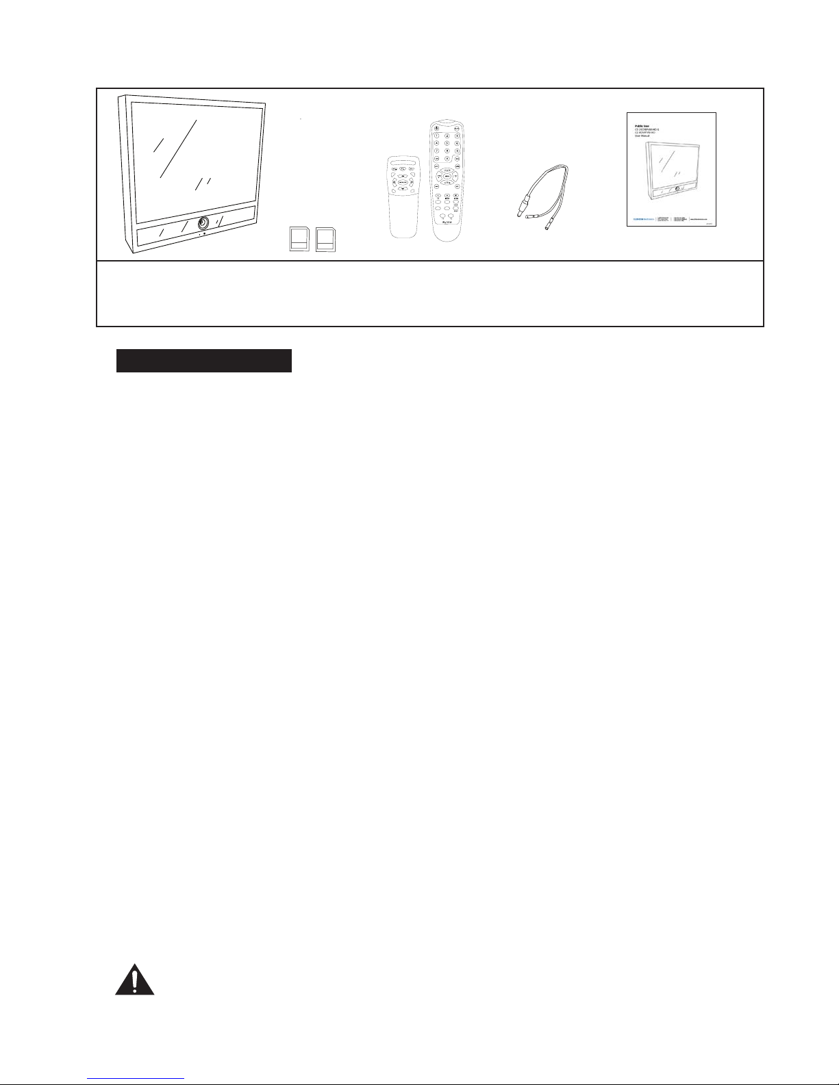
Unpacking your display
Your Public View display comes with the remote control and power connector. Carefully
remove the display from it’s packing and set the unit on a rm surface. Save the packing in
case of future service requirements.
NOTE: Any shipment of the display must have the protective plastic cover taped to the
front of the display to prevent shipping damage.
Installation of the display
The display should be located where it will have the most eect on deterring potential
shoplifting. Keep in mind the lighting conditions, viewing area, ease of installation, and
distance from the power supply when choosing a location. The display is compatible with
many available wall and ceiling mounts, consult your dealer for suggestions. The rear of the
display has a VESA 100mm mounting pattern that accepts M4 screws. Please refer to the
installation instructions on the particular mounting bracket and details of how to install.
Connecting the display
This display requires a 24V DC power supply. Locate the applicable AC to DC power supply
in a suitable location where there is an AC power source, and access to run the low voltage
cable to the display.
For single unit power supplies, you will need to keep the distance from the power supply
to the display less than 25 ft. For multiple unit power supplies, the power supply can be
located at further distances from the displays at a central location. Please refer to the specic
power supply installation instructions for recommended wire size and distances.
Caution: Do not connect the power connector to the display when energized,
doing so may damage the electronics inside the display. Connect power supply
to unit, then to 120v wall outlet.
POWER AUTO UP DOWN MENU
SD Card
16
GB
SD Card
2
GB
POWER AUTO UP DOWN MENU
SD Card
16
GB
SD Card
2
GB
CE-DVRPVM 2 SDHC Cards
• DVR (16GB)
• Video (2GB)
Remote Controls
• DVR
• Display
User ManualPower Pigtail
(for Hardwiring)
POWER AUTO UP DOWN MENU
SD Card
16
GB
SD Card
2
GB
PACKAGE CONTENTS
POWER AUTO UP DOWN MENU
SD Card
16
GB
SD Card
2
GB

5
Adjusting the Display
The display comes from the factory in a pre-set conguration that will be very close to the
nal set up for most installations. Minor adjustments can be made to the monitor and camera
to optimize the picture quality for a particular installation when required.
Adjusting the monitor
The monitor can be adjusted by either the included remote control, or with the OSD (On
Screen Display) buttons located at the rear of the monitor. These controls will adjust all
parameters of the display.
OSD Buttons
Power Button – On/O function. This will power o both the display and the internal
camera simultaneously.
Menu Button – To adjust audio, video, signal, tools, language use up & down buttons.
a. Push menu button once.
b. Push up or down button to pick category.
c. Push menu button for sub-category.
d. Push up or down button for movement within sub-category.
e. When sub-category is chosen, push menu button again.
f. Push up or down button to make your adjustment.
g. After adjustment has been made, menu display will turn o automatically.
Auto Button – Switches video source. Steps back to previous screen when in menu.
POWER AUTO UP DOWN MENU
SD Card
16
GB
SD Card
2
GB

6
SD Card
Inserted
Light Camera
IR Sensor
LED
Flasher
PIR
Sensor DVR SD
card slot
Video SD
card slot
OSD menu buttons
Power Indicator Light
BNC Output
Audio Switch
Sensor Switch
Sensitivity Dial
Dwell Time Dial
Power Supply Input
OSD Board
Camera Controls
SD Card
Inserted
Light -
(behind glass)
CE-8DVRPVM-HD
CE-20DVRPVM-HD
Camera LED
Flasher
PIR
Sensor
OSD menu
buttons
BNC Output
Audio Switch
Sensitivity Dial
Sensor Switch
Dwell Time Dial
DVR SD
card slot
Video SD
card slot
Power
Supply
Input VGA Input
Features
OSD
Board
Controls
(bottom)
7
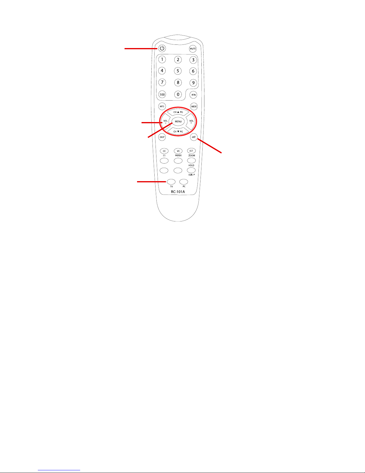
Power – On/O function. This will power o both the display and the internal camera.
Menu – To adjust audio, video, signal, tools, language use up & down buttons.
• Push MENU button once.
• Use arrow buttons located around the MENU button to pick category.
• When correct category is chosen, press VOL- and VOL+ buttons to adjust given parameter of
display.
• When adjustment of selected parameter is done, press MENU again to go back to the previous
screen, or simply wait for the menu screen to time out.
Sleep (ZZZ) –Used to set a sleep timer from 10-90 minutes. This will turn the display o after the
programmed amount of time. Continue pressing the sleep button to select the desired time, or
to turn the function o.
TV (source) –Switches video sources. (use to enter DVR menu).
Remote Control
TV (source)
Display Remote
Power
Selection Arrows
Menu
Sleep

8
Display Set-up
Video Menu: The display should be pre-set for most installations, however if some adjustment
is necessary, we suggest you follow these recommendations by pressing the MENU button on
the Display remote:
1. First adjust the BRIGHTNESS control to set the black level so that the images are at their
brightest while the black images are still black. Do not adjust too high where the black
portions of the image become gray or the image will have a “washed out” appearance.
2. Set the CONTRAST control to set the white level so that the images are at their brightest
without losing denition in the white portions of the image.
3. Adjust the COLOR control to achieve a realistic image of the items within the viewing area.
4. Adjust the TINT control if the image has bluish or reddish tint to the white portions of the
image.
5. Adjust the SHARPNESS lower if the image appears too grainy or pixelated. Increase the
SHARPNESS if the image appears too soft. Note: Adjust the SHARPNESS control only
after adjusting the camera lens for optimum focus.
6. The RESET selection can be used to return the Video settings back to the factory defaults.

9
Feature Controls Menu
1. The SLEEP TIMER is adjustable from 0min to 90min. After which time, the display will time
out until motion
2. The LANGUAGE can be changed to one of the following: English, French, German, Spanish,
Italian, Dutch, Greek, Swedish.
3. In the OSD CONTROL menu you can set the horizontal and vertical position of the OSD
menu, as well as rotate or mirror the menu., and control the duration the menu is on screen
2-16 seconds.
4. The LED light on the front of the unit can be turned on or o using the LED CONTROL
function.
5. In the MESSAGE CONTROL setting, you can turn the message on the bottom of the screen
on or o, as well as select the message to read “WELCOME” or “RECORDING IN PROGRESS”.
You can also control the message to ash on and o, or be steady on.
* 6. Pressing the left (VOL -), or right (VOL +) buttons under the FACTORY RECALL selection will
return all display settings back to the factory defaults. Doing so will void all of your custom
settings.
Audio Menu
1. The Audio Menu will not be used on this unit. It has no impact on the volume of the motion
chime that is set on the back of the unit. The MUTE function on the remote also has no
impact on the motion chime.

10
v.01.20.10
CLINTON Electronics
6701 Clinton Road
Loves Park, IL 61111
1.800.447.3306 Sales
1.800.549.6396 Support
1.800.633.8712 Fax
www.clintonelectronics.com
1. CHANGE THE DURATION OF CAMERA IMAGE ON SCREEN
t*ODSFBTFUVSODMPDLXJTFUIFi%XFMM5JNFwEJBMUPBMMPXUIF
-$%UPEJTQMBZUIFDBNFSBJNBHFMPOHFSPOUIFTDSFFO
t%FDSFBTFUVSODPVOUFSDMPDLXJTFUIFi%XFMM5JNFwEJBMUP
BMMPXUIF-$%UPEJTQMBZUPDZDMFCBDLUPUIFQSFMPBEFE+1&(JNBHF
POUIF4%$BSENPSFGSFRVFOUMZ
LCD CONTROLS PIR SENSOR CONTROLS
2. TURN OFF THE STATIC JPEG- SD CARD IMAGE
4XJUDIJOHUIFi4FOTPSwTXJUDIUPi0''wEJTBCMFTUIF1*34FOTPSXIJDI
EJTBCMFTUIF+1&(JNBHFGSPNBQQFBSJOHPOUIFTDSFFO
3. CHANGE THE SENSITIVITY OF THE MOTION SENSOR
t5VSOJOHUIFi4FOTJUJWJUZwEJBMDMPDLXJTF*ODSFBTFTUIFTFOTJUJWJUZ
t5VSOJOHUIFi4FOTJUJWJUZwEJBMDPVOUFSDMPDLXJTF%FDSFBTFTUIFTFOTJUJWJUZ
4. TURN OFF THE MOTION AUDIO
4XJUDIJOHUIFi$IJNFwTXJUDIUPi0''wEJTBCMFTUIFBVEJPUIBUJT
JOJUJBUFECZUIFNPUJPOTFOTPS
WHEN SD CARD IS INSERTED,
YOU MUST POWER CYCLE.
You can do this by pushing the POWER
button on the long remote,
or by unplugging the power cord from the wall.
%XFMMUJNF
4FOTJUJWJUZ
4FOTPS
$IJNF
0/
0''
0/
0''
_+
_+
CHANGE JPEG IMAGE
3. CHANGE THE PRE-LOADED “WARNING” JPEG IMAGE:
t*OTFSUUIF4%$BSEJOUPZPVSDPNQVUFSPS4%$BSESFBEFS
t.PWFZPVSEFTJSFE+1&(JNBHFPOUPUIF4%$BSEGPMEFS
t%FMFUFUIFPSJHJOBMi8"3/*/(w+1&(JNBHF
t-FBWJOHNPSFUIBOPOF+1&(JNBHFPOUIF4%$BSEXJMMSFTVMU
JOUIFEFWJDFDZDMJOHUISPVHIBMMMPBEFEJNBHFT
t*OTFSUUIF4%$BSECBDLJOUPUIF$&%7317.XJUIUIFDPOUBDUT
GBDJOHPVUBTTIPXOJOUIFJNBHFUPUIFSJHIU%0/05'03$&*5*/
tWHEN SD CARD IS INSERTED,YOU MUST POWER CYCLE THE UNIT.
You can do this by pushing the POWER button on the long remote,
or by unplugging the power cord from the wall.
t"O4%$BSE.645CFJOTFSUFEPSZPVXJMMTFFBi4FUUJOHTw.FOVXIFO
the device is powered on.
6TJOHUIFMPOHSFNPUF
t1SFTTUIFi.&/6wCVUUPO
t4DSPMMEPXOUPFOUFSUIFi'FBUVSF$POUSPMTwNFOV
t1SFTTSJHIUUPFOUFSUIFGFBUVSFTFMFDUJPO
t1SFTTEPXOVOUJMZPVSFBDIUIFi-&%$POUSPMw
t1SFTTSJHIUUPTXJUDIUIFMFEUPi0''w
t1SFTTi.&/6wUPFYJUUIFNFOVUIVTTBWJOHUIFOFXTFUUJOHT
.&/6
$) 1(
70-
+
$) 1(
70-
+
.&/6
6TJOHUIFMPOHSFNPUF
t1SFTTUIFi.&/6wCVUUPO
t4DSPMMEPXOUPFOUFSUIFi'FBUVSF$POUSPMTwNFOV
t1SFTTSJHIUUPFOUFSUIFGFBUVSFTFMFDUJPO
t1SFTTEPXOVOUJMZPVSFBDIUIFi.FTTBHF$POUSPMw
t1SFTTSJHIUUPFOUFSUIFNFTTBHF$POUSPM4FUUJOHT
t1SFTTSJHIUUPUVSOUIFNFTTBHF0/PS0''
t1SFTTEPXOUPTFMFDUi.FTTBHFw
t1SFTTSJHIUUPDIBOHFUIFNFTTBHFGSPN
i3&$03%*/(*/130(3&44wUPi8&-$0.&w
t1SFTTEPXOUPTFMFDUi'MBTIw
t1SFTTSJHIUUPBTXJUDIGSPNB'MBTIJOHUPB4UFBEZPONFTTBHF
t1SFTTi.&/6wUPFYJUUIFNFOVUIVTTBWJOHUIFOFXTFUUJOHT
.&/6
$) 1(
70-
+
$) 1(
70-
+
70-
+
$) 1(
70-
+
$) 1(
70-
+
.&/6
On the CE-8DVRPVM-HD, the JPEG IMAGE SD Card slot
is located on the upper side of the access panel.
5IF%73JTTFUGSPNUIFGBDUPSZUPSFDPSEPONPUJPO5IFTFTFUUJOHTIBWFCFFOQSFMPBEFEBOETIPVMEOPUCFDIBOHFE
5IFPOMZSFRVJSFEDIBOHFTBSFGPSNBUUJOHUIF4%DBSETFUUJOHUIFMPDBMUJNFBOEJGEBZMJHIUTBWJOHTUJNF%45JTSFDPHOJ[FEJOZPVSBSFB
5IF1*3TFOTPSQJOIPMFMPDBUFEGSPOUDFOUFSPOVOJUDPOUSPMTUIFTDSFFO
TXJUDIJOHPGUIFøBTIDBSEQMBZFSUPUIFCVJMUJODBNFSB*UBMTPDPOUSPMT
UIFBVEJP#FTVSFUPLFFQUIFTNBMMIPMFPQFOBUBMMUJNFTBOEGSFFPGEVTU
*UEPFTOPUDPOUSPMUIF%73NPUJPOSFDPSEJOHUIF3&$03%*/(*/130(3&44
UFYUPOUIFTDSFFOPSUIFGSPOU-&%
2. TURN THE BOTTOM SCREEN MESSAGE ON/OFF/SOLID
1. TURN THE FRONT LED FLASHING ON/OFF
Quick Reference Guide for CE-20DVRPVM-HD & CE-8DVRPVM-HD
PIR Sensor Controls
Change JPEG Image
• Insert the SD-Card into your computer or SD Card reader.
• Move your desired JPEG image onto the SD Card folder.
• Leaving more than one JPEG image on the SD Card will result in the device cycling through all
loaded images.
• Insert the SD-Card back into the CE-DVRPVM with the contacts facing out, as shown in the image
to the right - DO NOT FORCE IT IN.
• WHEN SD CARD IS INSERTED, YOU MUST POWER CYCLE THE UNIT. You can do this by pushing
the POWER button on the long remote, or by unplugging the power cord from the wall.
• An SD Card MUST be inserted, or you will see a “Settings” Menu when the device is powered on.
v.01.20.10
CLINTON Electronics
6701 Clinton Road
Loves Park, IL 61111
1.800.447.3306 Sales
1.800.549.6396 Support
1.800.633.8712 Fax
www.clintonelectronics.com
1. CHANGE THE DURATION OF CAMERA IMAGE ON SCREEN
t*ODSFBTFUVSODMPDLXJTFUIFi%XFMM5JNFwEJBMUPBMMPXUIF
-$%UPEJTQMBZUIFDBNFSBJNBHFMPOHFSPOUIFTDSFFO
t%FDSFBTFUVSODPVOUFSDMPDLXJTFUIFi%XFMM5JNFwEJBMUP
BMMPXUIF-$%UPEJTQMBZUPDZDMFCBDLUPUIFQSFMPBEFE+1&(JNBHF
POUIF4%$BSENPSFGSFRVFOUMZ
LCD CONTROLS PIR SENSOR CONTROLS
2. TURN OFF THE STATIC JPEG- SD CARD IMAGE
4XJUDIJOHUIFi4FOTPSwTXJUDIUPi0''wEJTBCMFTUIF1*34FOTPSXIJDI
EJTBCMFTUIF+1&(JNBHFGSPNBQQFBSJOHPOUIFTDSFFO
3. CHANGE THE SENSITIVITY OF THE MOTION SENSOR
t5VSOJOHUIFi4FOTJUJWJUZwEJBMDMPDLXJTF*ODSFBTFTUIFTFOTJUJWJUZ
t5VSOJOHUIFi4FOTJUJWJUZwEJBMDPVOUFSDMPDLXJTF%FDSFBTFTUIFTFOTJUJWJUZ
4. TURN OFF THE MOTION AUDIO
4XJUDIJOHUIFi$IJNFwTXJUDIUPi0''wEJTBCMFTUIFBVEJPUIBUJT
JOJUJBUFECZUIFNPUJPOTFOTPS
WHEN SD CARD IS INSERTED,
YOU MUST POWER CYCLE.
You can do this by pushing the POWER
button on the long remote,
or by unplugging the power cord from the wall.
%XFMMUJNF
4FOTJUJWJUZ
4FOTPS
$IJNF
0/
0''
0/
0''
_+
_+
CHANGE JPEG IMAGE
3. CHANGE THE PRE-LOADED “WARNING” JPEG IMAGE:
t*OTFSUUIF4%$BSEJOUPZPVSDPNQVUFSPS4%$BSESFBEFS
t.PWFZPVSEFTJSFE+1&(JNBHFPOUPUIF4%$BSEGPMEFS
t%FMFUFUIFPSJHJOBMi8"3/*/(w+1&(JNBHF
t-FBWJOHNPSFUIBOPOF+1&(JNBHFPOUIF4%$BSEXJMMSFTVMU
JOUIFEFWJDFDZDMJOHUISPVHIBMMMPBEFEJNBHFT
t*OTFSUUIF4%$BSECBDLJOUPUIF$&%7317.XJUIUIFDPOUBDUT
GBDJOHPVUBTTIPXOJOUIFJNBHFUPUIFSJHIU%0/05'03$&*5*/
tWHEN SD CARD IS INSERTED,YOU MUST POWER CYCLE THE UNIT.
You can do this by pushing the POWER button on the long remote,
or by unplugging the power cord from the wall.
t"O4%$BSE.645CFJOTFSUFEPSZPVXJMMTFFBi4FUUJOHTw.FOVXIFO
the device is powered on.
6TJOHUIFMPOHSFNPUF
t1SFTTUIFi.&/6wCVUUPO
t4DSPMMEPXOUPFOUFSUIFi'FBUVSF$POUSPMTwNFOV
t1SFTTSJHIUUPFOUFSUIFGFBUVSFTFMFDUJPO
t1SFTTEPXOVOUJMZPVSFBDIUIFi-&%$POUSPMw
t1SFTTSJHIUUPTXJUDIUIFMFEUPi0''w
t1SFTTi.&/6wUPFYJUUIFNFOVUIVTTBWJOHUIFOFXTFUUJOHT
.&/6
$) 1(
70-
+
$) 1(
70-
+
.&/6
6TJOHUIFMPOHSFNPUF
t1SFTTUIFi.&/6wCVUUPO
t4DSPMMEPXOUPFOUFSUIFi'FBUVSF$POUSPMTwNFOV
t1SFTTSJHIUUPFOUFSUIFGFBUVSFTFMFDUJPO
t1SFTTEPXOVOUJMZPVSFBDIUIFi.FTTBHF$POUSPMw
t1SFTTSJHIUUPFOUFSUIFNFTTBHF$POUSPM4FUUJOHT
t1SFTTSJHIUUPUVSOUIFNFTTBHF0/PS0''
t1SFTTEPXOUPTFMFDUi.FTTBHFw
t1SFTTSJHIUUPDIBOHFUIFNFTTBHFGSPN
i3&$03%*/(*/130(3&44wUPi8&-$0.&w
t1SFTTEPXOUPTFMFDUi'MBTIw
t1SFTTSJHIUUPBTXJUDIGSPNB'MBTIJOHUPB4UFBEZPONFTTBHF
t1SFTTi.&/6wUPFYJUUIFNFOVUIVTTBWJOHUIFOFXTFUUJOHT
.&/6
$) 1(
70-
+
$) 1(
70-
+
70-
+
$) 1(
70-
+
$) 1(
70-
+
.&/6
On the CE-8DVRPVM-HD, the JPEG IMAGE SD Card slot
is located on the upper side of the access panel.
5IF%73JTTFUGSPNUIFGBDUPSZUPSFDPSEPONPUJPO5IFTFTFUUJOHTIBWFCFFOQSFMPBEFEBOETIPVMEOPUCFDIBOHFE
5IFPOMZSFRVJSFEDIBOHFTBSFGPSNBUUJOHUIF4%DBSETFUUJOHUIFMPDBMUJNFBOEJGEBZMJHIUTBWJOHTUJNF%45JTSFDPHOJ[FEJOZPVSBSFB
5IF1*3TFOTPSQJOIPMFMPDBUFEGSPOUDFOUFSPOVOJUDPOUSPMTUIFTDSFFO
TXJUDIJOHPGUIFøBTIDBSEQMBZFSUPUIFCVJMUJODBNFSB*UBMTPDPOUSPMT
UIFBVEJP#FTVSFUPLFFQUIFTNBMMIPMFPQFOBUBMMUJNFTBOEGSFFPGEVTU
*UEPFTOPUDPOUSPMUIF%73NPUJPOSFDPSEJOHUIF3&$03%*/(*/130(3&44
UFYUPOUIFTDSFFOPSUIFGSPOU-&%
2. TURN THE BOTTOM SCREEN MESSAGE ON/OFF/SOLID
1. TURN THE FRONT LED FLASHING ON/OFF
Quick Reference Guide for CE-20DVRPVM-HD & CE-8DVRPVM-HD
11
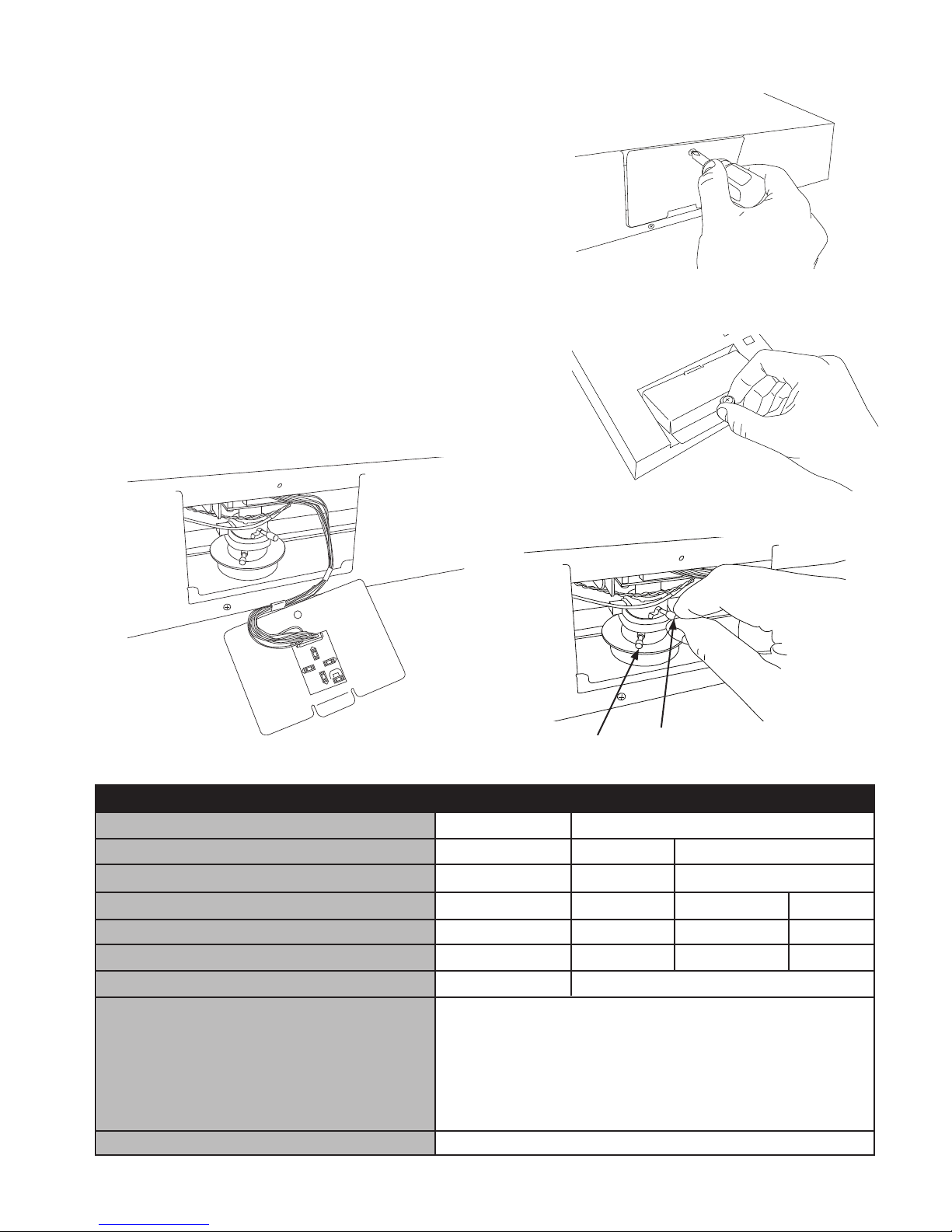
Access to the Camera and OSD Board
The access door to the camera and OSD Board is located
at the bottom of the 20”unit, and back of the 8”unit. A
Phillips screwdriver is required to remove the access
panel screw from the 20’unit (Fig. A), place the screw in a
location where it will not be lost. The access panel for the
8” unit can be nger loosened (Fig A2).
The OSD board is attached to the access panel for easy
adjustment of the parameters of the camera while
viewing the front of the screen (Fig. B).
The Zoom and Focus on the 20” unit can be adjusted by
loosening the two adjustment dials on the lens (Fig. C).
When the desired Zoom and Focus settings are reached,
nger tighten the dials; do not over tighten.
LENS (Selection)
SHUTTER (Condition and Speed Control)
WHITE BALANCE (Control)
BACKLIGHT (Backlight Compensation)
AGC (Auto Gain Control)
DNR (Digital Noise Reduction)
SENS-UP (Low Illuminance)
SPECIAL
EXIT
MANUAL
ESC
ATW
OFF
OFF
OFF
OFF
CAMERA ID
SYNC
PRIVACY
SHARPNESS
RETURN
DC
MANUAL
AWC
LOW
LOW
LOW
AUTO
FLK
MANUAL
MIDDLE
MIDDLE
MIDDLE
HIGH
HIGH
HIGH
SETUP MENU
OSD Menu
POWER AUTO UP DOWN MENU
SD Card
16
GB
SD Card
2
GB
Focus
Zoom
POWER AUTO UP DOWN MENU
SD Card
16
GB
SD Card
2
GB
UP
RIGHT
LEFT
DOWN SET
B.
C.
COLOR
MOTION DETECTION
MIRROR
RESET
A. CE-20DVRPVM-HD
A2. CE-8DVRPVM-HD
12
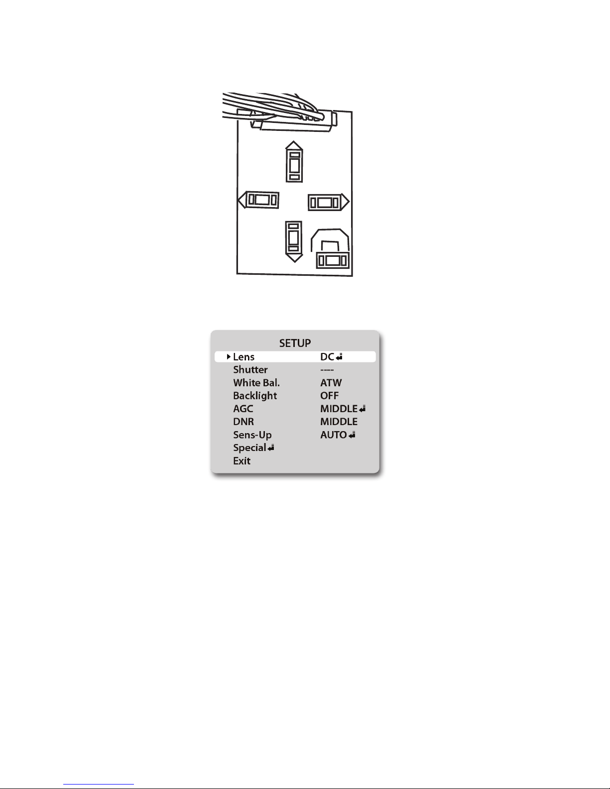
Settings
Settings can be made using the 5 button OSD Board located on the under side of the door.
1. Press the SET button to activate On-Screen SETUP Menu
2. Select the function you wish to adjust using the UP or DOWN button.
3. When the LEFT or RIGHT button is pressed, the available modes are displayed (*Note: Some
menu selections may not have multiple modes to select). Keep pressing the button until you get
the mode you wish to operate.
4. Press SET to enter the value settings (if applicable) and adjust as necessary with the LEFT and
RIGHT buttons.
5. Press SET to apply the value, and exit the current value settings screen.
6. Repeat steps 2-5 to adjust the appropriate settings.
4. Select EXIT from the menu selections, and then press the SET button to exit the SETUP menu.
UP
RIGHT
LEFT
DOWN SET
13
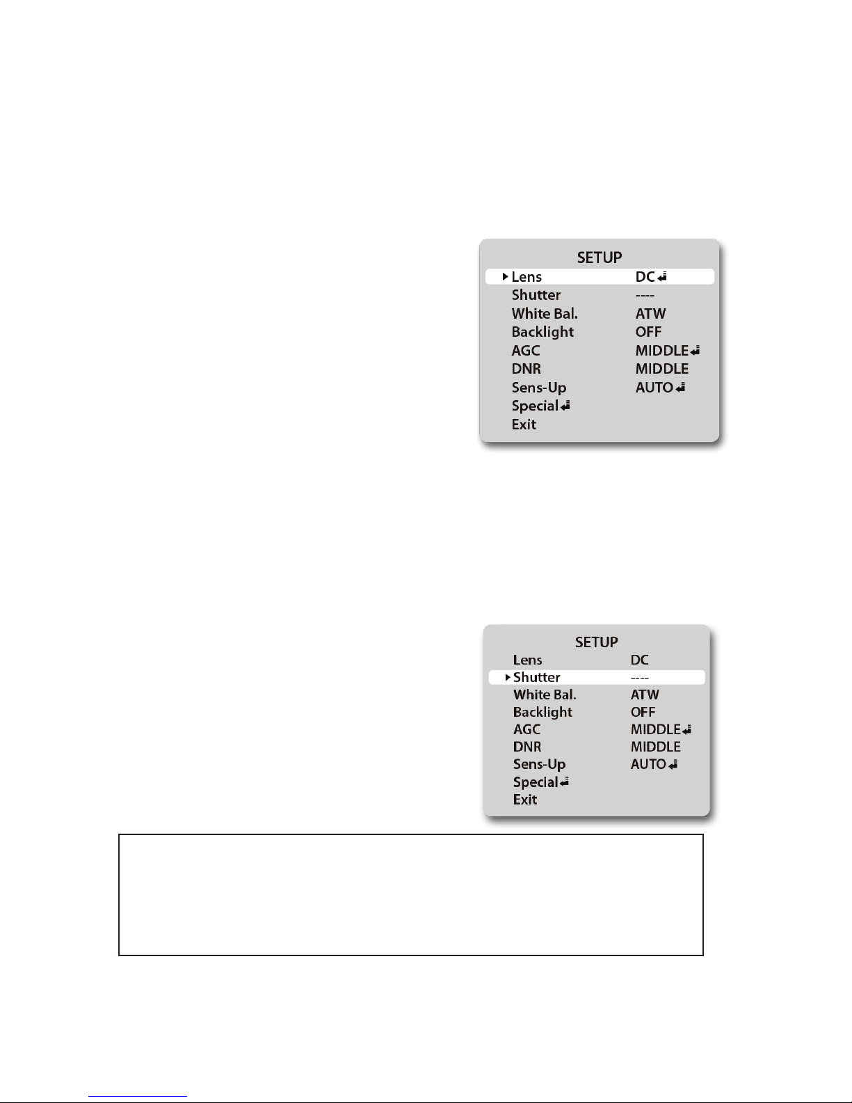
Lens (selection)
1. When the SETUP menu is displayed on the screen, position the arrow to point to LENS by using the
UP or DOWN button.
2. You may select the type of lens you wish to use by pressing the LEFT or RIGHT button.
3. Press the SET button to return to previous menu.
DC: Auto iris lens selection-
• The optimum level of brightness can be
adjusted within the range of 1 ~ 70.
MANUAL: Manual lens selection-
• If MANUAL mode is selected, the brightness
can be adjusted in ESC mode.
Shutter (condition and speed control)
1. When the SETUP menu is displayed on the screen, position the arrow to point to SHUTTER by
using the UP or DOWN button.
2. Select the shutter mode by pressing the LEFT or RIGHT button.
FLK: Select FLK mode when ickering occurs
on the screen due to an imbalance between
illumination and frequency.
NTSC Model:1/100, PAL Model 1/120
ESC: When ESC mode is on, the shutter speed
is controlled automatically according to the
brightness of the screen.
3. Press the SET button to return to previous menu.
• While using the internal synchronous system, if the shutter setting is on ESC, and
the camera is directly facing a bright uorescent light, the image on the screen
can be adversely aected. Therefore, choose the installation location with care.
• When MANUAL mode is on, the SENS-UP function does not operate.

14
White Balance
The screen color can be adjusted by using the WHITE BALANCE function.
1. Position arrow to point to WHITE BAL. using UP or DOWN button.
2. Select the mode you wish to operate by pressing the LEFT or RIGHT
ATW (Auto Tracking White Balance):
This mode can be used within the color
temperature range 1,800ºK ~ 10,500ºK (eg.
uorescent light, outdoor, sodium vapor
lamp, or inside tunnels)
AWC (Auto White Balance Control): Press
SETUP button while the camera is directed
at a piece of white paper to obtain the
optimum state under current illumination. If
the environment including the light source
is changed, you will have to adjust the white
balance again.
MANUAL: This mode enables ner
adjustment. Select manual adjustment mode,
and press“SETUP” button. Set the appropriate
color temperature, and then increase or
decrease the red and blue color values while
monitoring the color changes on an object.
3. Press the SET button to return to previous menu.
• The WHITE BALANCE function may not operate properly under the following
conditions. In such case, select the AWC mode.
1. When an object’s surroundings have a very high color temperature (eg, a clear
sky and sunset)
2. When an object’s surroundings are dark
3. If the camera directly faces an uorescent light or is installed in a place where
there are considerable changes in illumination, the WHITE BALANCE function
may become unstable.
15
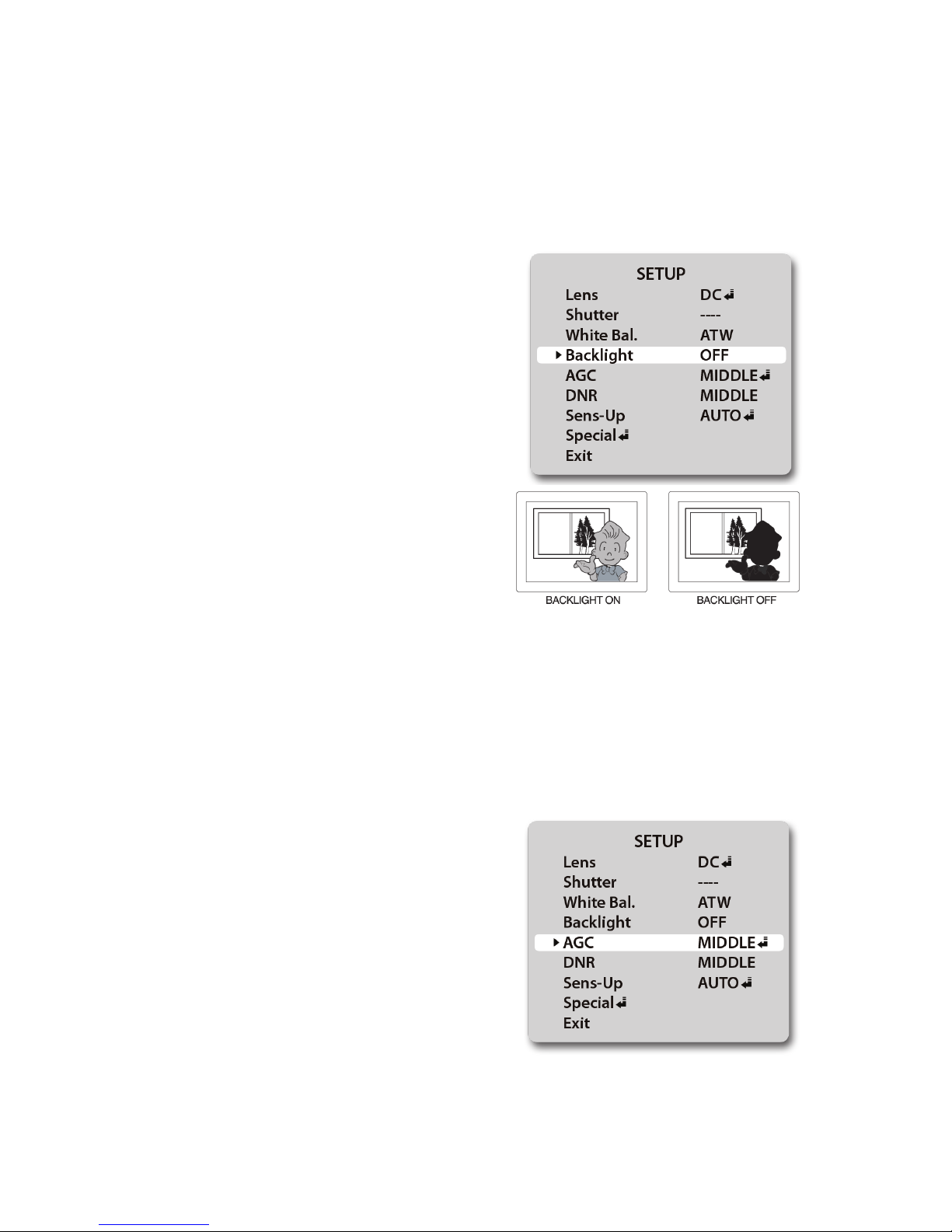
BLC (Backlight Compensation)
When there is a strong backlight behind the object, clear images of the background as well as the object
can still be obtained by using the BACKLIGHT function.
1. Position the arrow to point to BACKLIGHT on the SETUP menu by using the UP or DOWN button.
2. Select the mode you wish to operate by pressing the LEFT or RIGHT button.
OFF: Select when there is no backlight
interference
LOW: Select when there is a slight backlight
interference
MIDDLE: Select when there is a moderate
amount of backlight interference
HIGH: Select when there is a high amount of
backlight interference
3. Press the SET button to return to previous menu.
AGC (Auto Gain Control)
1. Position the arrow to point to AGC on the SETUP menu by using the UP or DOWN button.
2. Select the mode you wish to operate by pressing the LEFT or RIGHT button. As the level of gain
increases, the screen gets brighter and the level of noise also increases.
OFF: The gain is xed at 6dB
LOW: The gain increases or decreases within
the range of 6dB ~ 18dB.
MIDDLE: The gain increases or decreases
within the range of 6dB ~ 30dB.
HIGH: The gain increases or decreases within
the range of 6dB ~ 42dB.
3. Press the SET button to return to previous menu.
16
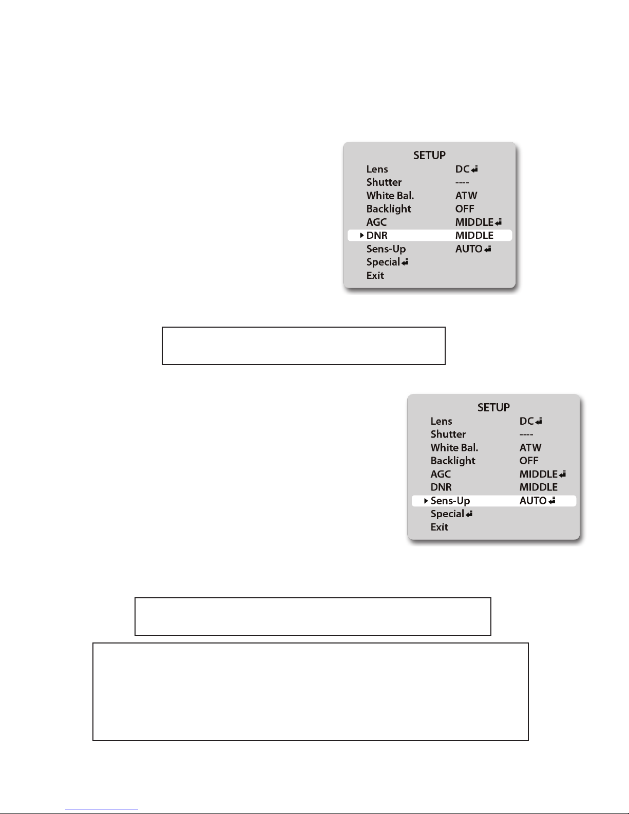
DNR (Digital Noise Reduction)
The background noise in the low light level decreases automatically as the level of gain changes.
1. Position the arrow to point to DNR on the SETUP menu by using the UP or DOWN button.
2. Select the mode you wish to operate by pressing the LEFT or RIGHT button.
OFF: There is no reduction in noise level.
LOW: There is a small reduction in noise level
with almost no ghost image.
MIDDLE: The most eective mode. There is
a sucient reduction in noise levels, without
causing much ghost imaging.
HIGH: The level of noise is greatly reduced,
however there is an increase in ghost imaging.
3. Press the SET button to return to previous menu.
• When AGC is turned o, DNR does not operate.
SENS-Up (Low illuminance)
SENS-UP helps maintain a bright, clear screen image by automatically
detecting changes in the level of light in low light level conditions.
1. Position the arrow to point to SENS-UP on the SETUP menu by
using the UP or DOWN button.
2. Select the mode you wish to operate by pressing the LEFT or RIGHT
button.
OFF: The function does not operate
AUTO: Low light level auto mode
3. Press the SET button to return to previous menu.
• When SHUTTER is in manual mode, SENS-UP does not operate.
• When AGC is turned o, SENS-UP does not operate.
• The maximum storage in low light level movement situations can be adjusted
by pressing the SETUP button in AUTO mode. (X2~X128).
• As the magnication increases, the screen gets brighter; however the motion
blur also increases.
• If storage magnication is increased while SENS-UP is operating, it may cause
noise, and spots may appear; however this is normal.
17
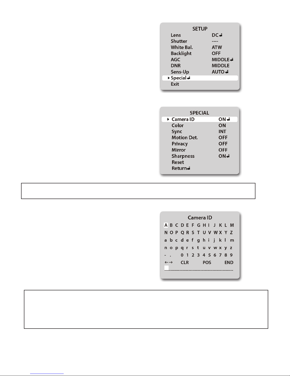
Special
1. Position the arrow to point to SPECIAL on the SETUP
menu by using the UP or DOWN button.
2. Enter the SPECIAL options menu by pressing the
SETUP button.
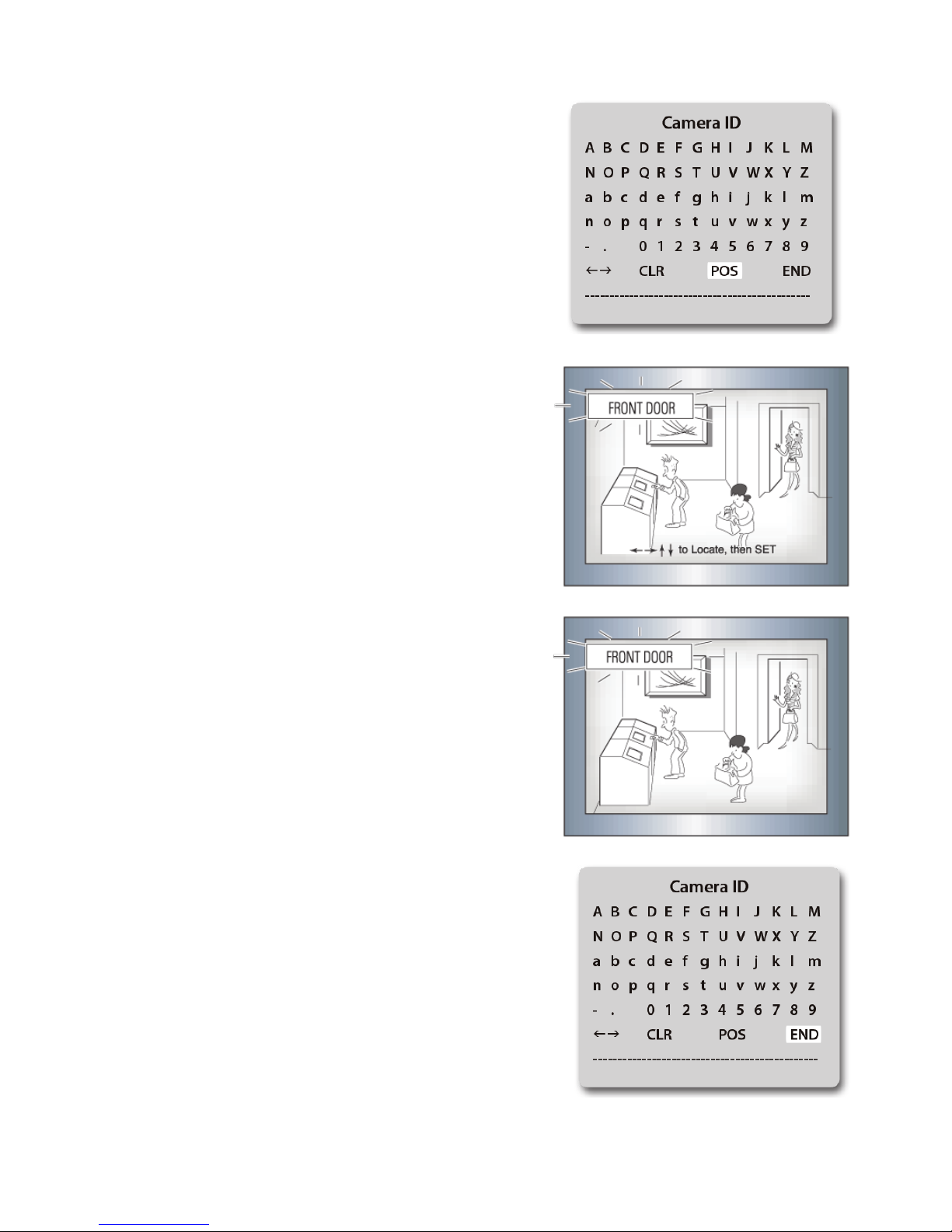
CAMERA ID: Use this function to input the
camera’s ID/name and have it appear on the
monitor.
• If “OFF” is selected, the ID/name does not appear on the monitor even if it has been entered.
1. Position the arrow to point to CAMERA ID by
using the UP or DOWN button.
2. Select ON by pressing the LEFT or RIGHT button.
3. Press the SET button to enter the ID menu.
4. Use the UP, DOWN, LEFT, and RIGHT buttons to
navigate to desired characters, and press SET to enter.
You can enter up to 15 characters.
• If the wrong name has been entered....
If you press the SET button after moving the cursor to CLR, all characters will be erased.
If you wish to correct a single character, move the cursor to the arrow at the bottom left of the screen,
and press SET as many times as needed until the cursor is over the character you wish to replace.
Next, position the cursor above the character you wish to replace it with, and press SET.
18
5. Move the cursor to“POS” and press the SET button. You will
now see a preview of how the ID/name will appear on the
screen.
6. Press LEFT, RIGHT, UP, or DOWN to position the ID/name
in the desired position on the screen.
7. Press SET to lock the ID/name in place, and return to the
previous CAMERA ID screen.
8. Navigate the cursor to END, and press SET to exit.

19
COLOR:
- AUTO: This camera has a function which automatically changes to the appropriate mode
for daytime or night-time. The camera is in COLOR mode for daytime, and automatically
switches to BW mode for night-time.
-ON: The color mode is selected by default, and the modes do not change automatically.
• When AGC is turned o, COLOR does not operate.
• When an infrared light is used, there may be a problem with focusing.
SYNC:
Two Synchronization modes are available: INTERNAL, and EXTERNAL
LINE-LOCK. In LINE- LOCK mode, the unit synchronizes the video signal
between cameras without a synchronous generator. The LINE-LOCK
synchronization is only used in the areas of 60Hz (NTSC Models) / 50Hz
(PAL Models).
• When the power frequency is 50Hz, you can not use the line-lock mode (NTSC Models)
• When the power frequency is 60Hz, you can not use the line-lock mode (PAL Models)
• SYNC mode is xed to INT in 12VDC input power.
-INT: Internal synchronization
-LL: External line-lock synchronization
-If you choose “LL” you can adjust the desired phase. Press the SET button.
-You can adjust the desired phase from 0 to 359.
MOTION DETECTION:
This device has a feature that allows you to monitor movements of activity in 4 dierent
areas on the screen. The words“MOTION DETECTED” will appear on the screen when
movement is detected, allowing for a single person to conduct supervision eciently.
The camera detects an object’s movement by sensing a change of outline, and level of
brightness and color.
• Press the SETUP button
- OFF: Motion detection mode is not active
- ON: Any motion in the selected areas will activate“MOTION
DETECTED” message
• Select the area you wish to observe from the 4 areas in AREA SEL.
• Turn areas 1-4 ON or OFF with AREA STATE
• Adjust the size of the motion detection area by using the UP, DOWN,
LEFT, and RIGHT buttons
• Press SET to enter the settings and return to the previous menu.
20
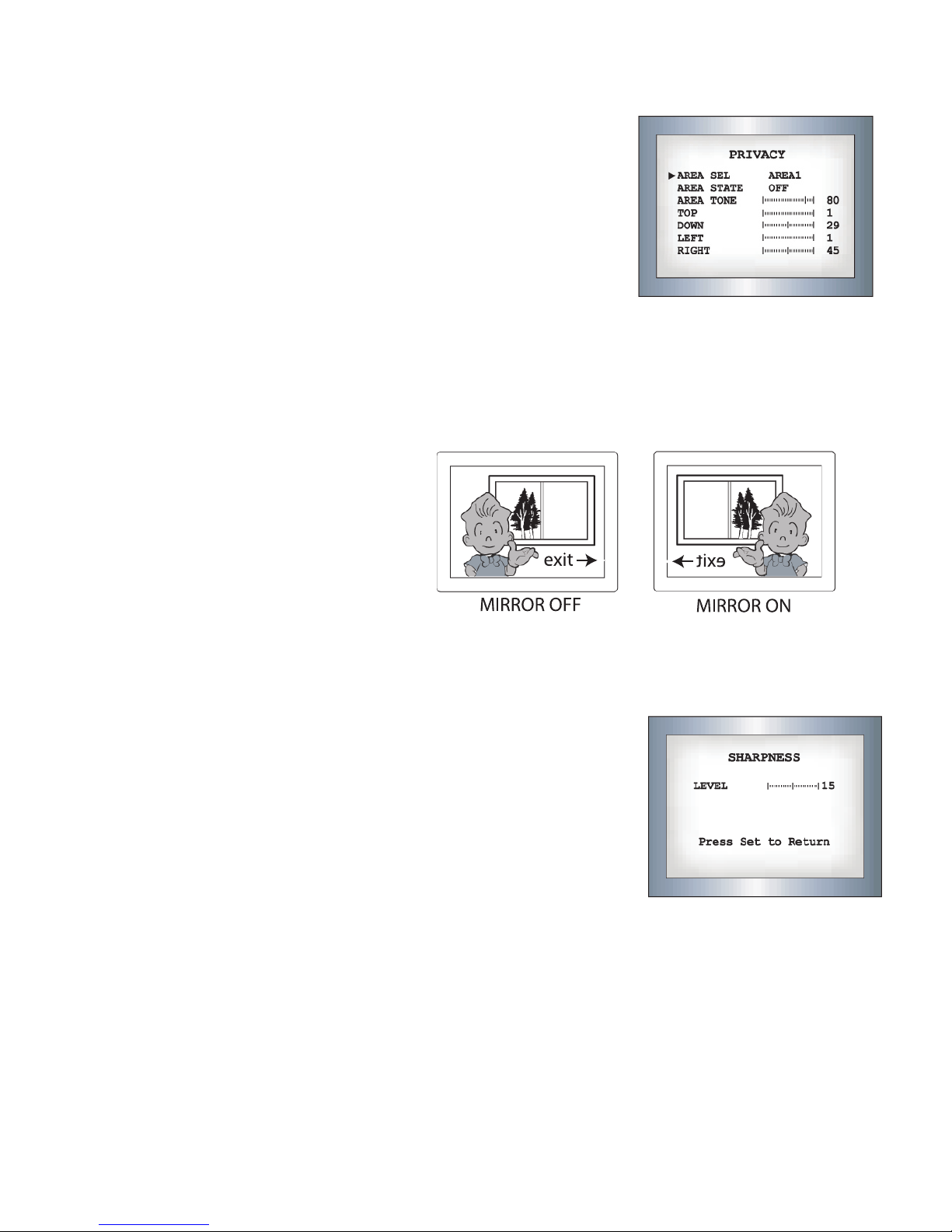
PRIVACY:
This mode conceals up to 4 areas you wish to be private during viewing, and recording playback.
- OFF: Disables PRIVACY mode
- ON: Activates PRIVACY mode
Press SET button to enter parameters.
• Select the area you wish to have private from the 4 areas in AREA SEL.
• Turn areas 1-4 ON or OFF with AREA STATE
• Change the color tone of the 4 areas with AREA TONE (0=Black, 100=white)
• Adjust the size of the privacy area by using the UP, DOWN, LEFT, and RIGHT buttons
• Press SET to enter the settings and return to the previous menu.
MIRROR:
- OFF: Normal mode
- ON: Sets a horizontal image inversion
SHARPNESS:
The outline of the video image becomes cleaner and more distinctive as
the level of SHARPNESS increases. If the level goes up excessively however,
it may aect the video image and generate noise.
-The available range of sharpness level is from 0 ~ 31.
RESET:
Returns all parameters to factory defaults set by the manufacturer.
RETURN:
Saves the SPECIAL menu settings, and returns to the SETUP menu.
EXIT:
Saves all settings, and exits the menu.
This manual suits for next models
1
Table of contents
Other Clinton Electronics Monitor manuals

Clinton Electronics
Clinton Electronics CE-M10A User manual

Clinton Electronics
Clinton Electronics Public View CE-M8SD-B User manual

Clinton Electronics
Clinton Electronics A-SERIES User manual

Clinton Electronics
Clinton Electronics CE-M27-HD-B User manual

Clinton Electronics
Clinton Electronics CE-M21PE User manual

Clinton Electronics
Clinton Electronics Public View CE-M19SD User manual

Clinton Electronics
Clinton Electronics CE-L07 User manual

Clinton Electronics
Clinton Electronics CE-M19S User manual

Clinton Electronics
Clinton Electronics CE-M21A-PIR Manual

Clinton Electronics
Clinton Electronics HD Series User manual


