Clinton 6000 Series User manual
THE
V
MANUAL NO. 137.780
REFER TO BACK OF PAGE FOR WARRANTY REGISTRATION.
IlUlPORTAN
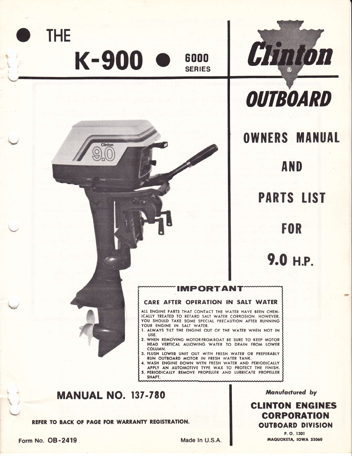
CARE AFTER OPERATION IN SATT WATER
ATT ENGINE PARIS THAT CONTACT THE V/ATER HAVE BEEN CHEM.
ICATI.Y TREATED TO RETARD SAI,T WATER CORROSION. HOWEVER,
YOU SHOUI.D TAKE SOME SPECIAT PRECAUTION ATTER RUNNING
YOUR ENGINE IN SATT WATER.
I. ATWAYS IITT IHE ENGINE OUT OF THE WATER WHEN NOT IN
USE.
2. WHEN REAoVtNG MoToRFRoMBoAT BE suRE ro KEEP MoroR
HEAD VER'ICAI, AII.OWING WAIER TO DRAIN FROM TOWER
cotuA N.
3. FTUSH TOWER UNIT OUT WITH FRESH WATER OR PREFERABI.Y
RUN OUTBOARD MOTOR IN FRESH WATER IANK.
.. WASH ENGINE DOWN WITH FRESH WATER AND PERIODICAI.TY
APPTY AN AUTOMOTIVE TYPE WAX TO PROTECT THE fINISH.
5. PERIODICATTY REAAOVE PROPETIER AND TUBRICATE PROPETTER
SHAFT.
K-900 0 r_?=1
OATBOARD
(lWl{ERS MA]IUAT
AilD
PARTS IIST
r0R
9.0 H.p.
Monutactured by
GLINTON ENGINES
CORPO,RATION
OUTBOARD DIVISION
P. O. t30t
,nAOUOKtrA, IOWA 52060
Form No. OB-241'9 Made ln U.S.A.
IMPORTANT
Owner's Responsibility qnd Operoting Sofety Check list
BE SURE TO READ AND DO THE FOLLOWING BEFORE OPERATING YOUR OUTBOARD MOTOR
l. lnclude a life vest for each passenger in boat, as required by U.S. Coast Guard, approved type
1,2 or 3 Personal Flotation Device. lf your boat is I6 feet or longer, you are also required to
carry a Iype 4 throwable Personal Flotation Device. You are responsible for the safety of your
passengers.
2. Close fuel shut-off valve before placing motor in tilt position on transom to prevent fuel leak-
age from carburetor.
3. Before slorting, moke sure your molor is securely mounied lo boot. Tighten clomp stud hon-
dles securely by hond. A motor sofety choin is ovo iloble ol your neoresl Outboord Deoler.
1. Be sure to hove on odequole supply of fuel on boot. Use o good grode of regulor leoded goso-
line or o oulomotive type non-leoded gosoline is permissoble. Do not fill gos lonk wilh motor
running or neor ony flome.
5. To prevent possible injury from the rotating propeller, do not attempt to remove motor from
water and do not place hand near moving propeller, or allow swimming near moving propeller
until unit has come to a complete stop.
6. Be sure to have pliers, screwdriver, spare spark plugs, wrench, shear pins and cotter pins in
boat whenever leaving shore.
7. ln case of an emergency, the engine can be stop,ped by placing the choke knob in full choke
position.
8. Open vent screw on filler cap at remote tank and fuel shut-off valve before attempting to start
motor.
9. Wipe remote fuel tank connector clean before connecting connector to outboard motor.
.l0. Squeeze primer bulb on fuel line of the remote fuel tank until it becomes firm.
I I . Read break-in instructions before running your new outboard motor.
12. To assure supreme safety and compliance with the law, you should acquaint yourself with
boating laws of the U.S. Coast Guard and with the laws of your state and locality.
v
.l
DESCRI
tNTRODUCTIOl{
You have now invested in an Air Cooled Outboard Motor
which has been engineered and built to the highest of quality
standards. Many hours of enjoyment are before you in boating
pleasure.
Read this Owner's Guide thoroughly before operating the
' motor. The instructions are concise and complete in operation
, and recommendations to assure best in care and performance'
\ ' As you read the instructions, keep in mind that maximum per-
' formance and service depend on the owner or operator. May
\ u we suggest that you practice tire step by step instructiotls to
be certain you are familiar with each operation.
Periodic servicing will .be required. It is recommended
that you consult a Clinton Service Gnter when service is re'
quired. 2 CYCLE FUEL IIIXTURE INSTRUCTIONS
Use a good grade of regular gasoline. Do not use non-lead-
ed gasoline. The use of premium gasolines will shorten spark
plug life. In a clean container thoroughly mix3,ourices( 50to 1
fuel mix) of a High Quality Outboard I\totor Oil (or its equi'
valent) of SAE 30 or 40 viscosity to one gallon of gasoline. Do
not use D.M. or D.S. rated oils. For best results strain mired
\'r" fuel through a fine screened funnel when filling gasoline tank.
BBEAK.IN PERIOD
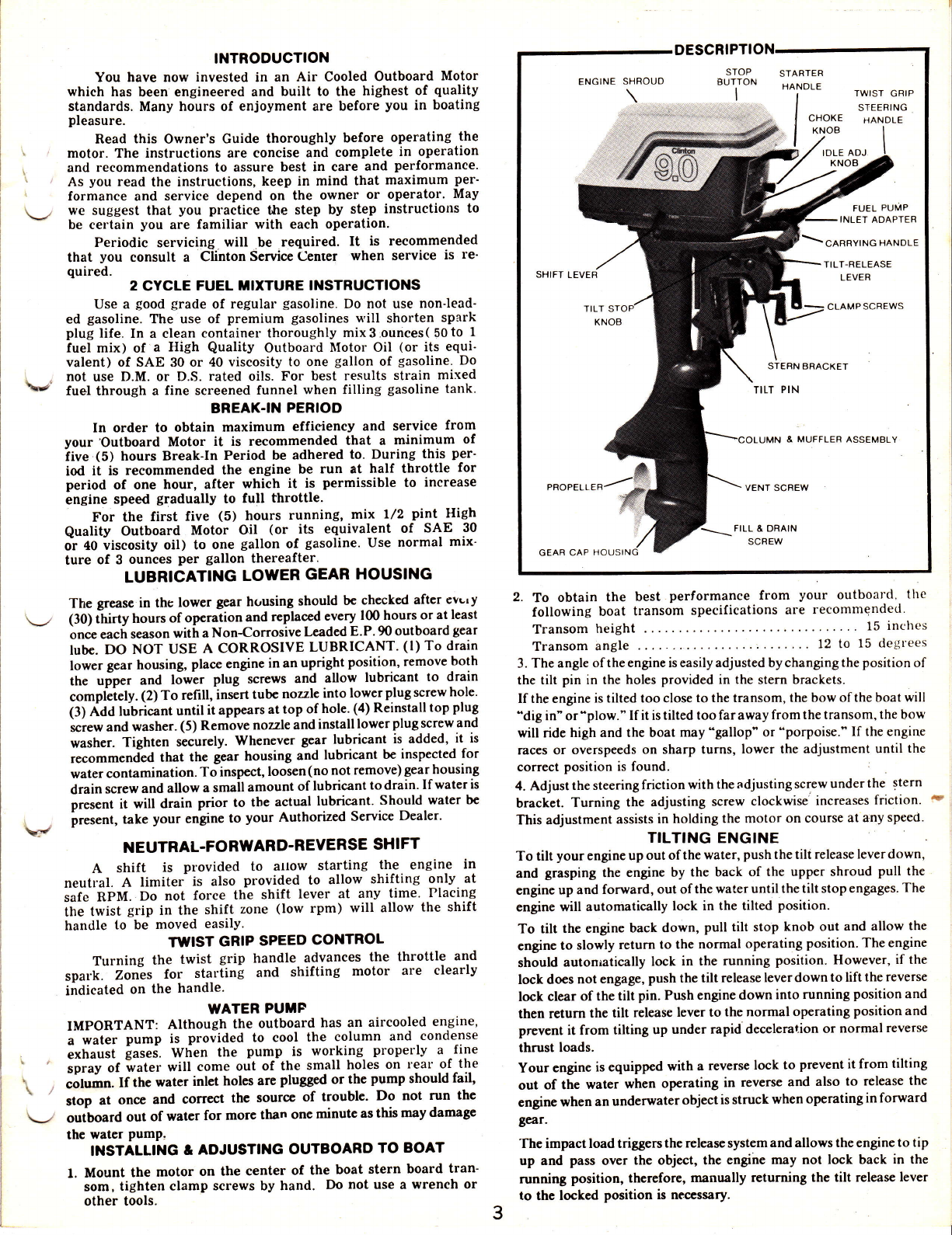
ENGINE SHROUD STOP
BUTTON
I
STABTER
HANDLE TWIST GRIP
STEERING
CHOKE HANDLE
KNOB I
JOB I
,o,-, oo, I
FUEL PUMP
INLET ADAPTER
\clnnvtruc Hnruole
SHIFT LEVEH
PROPELLER
GEAR CAP
TILT-RELEASE
LEVER
CLAMP SCREWS
E MUFFLER ASSEMBLY
In order to obtain maximum efficiency and service from
your'Outboard Motor it is recommended that a minimum of
iive (5) hours Break-In Period be adhered to. During this per'
iod it is recommended the engine be run at half throttle for
period of one hour, after which it is permissible to increase
engine speed gradually to full throttle.
For the first five (5) hours running, mix l/2 pint High
Quality Outboard Motor Oil (or its equivalent of SAE 30
o-r 40 viscosity oil) to one gallon of gasoline. Use normal mix'
ture of 3 ounces per gallon thereafter.
LUBRICATING LOWER GEAR HOUSING
The grease in thc lower gear housing should bc chccked after evLry
(30) thirty hours of opcration and replaced every l(X) hours or at least
on"" """h season witl a Non-Corrosive Leaded E.P. 90 outboard gear
lube. DO NOT USE A CORROSM LUBRICANT' (l) To drain
lower gear housing, place engine in an upright position' remove both
the ulper and lJwer plug screws and allow lubricant to drain
compleiely. (2) To refill, insert tubc nozzlc into lowcr plug screw hole'
(3) Add lubricant until it appears at top of hole.(4) Reinstall top plug
screw and washer. (5) Remove nozzle and install lower plug screw and
washer. Tighten securely. Whenever gear lubricant is added, it is
,."o--"n["d that the gear housing and lubricant be inspected for
water contamination. To inspect, loosen (no not remove) gear housing
drain screw and allow a smail amount of lubricant to drain. If water is
present it will drain prior to the actual lubricant' Should water be
present, take your engine to your Authorized Service Dealer'
NEUTRAL.FORWARD.REVERSE SHIFT
A shift is provided to attow starting the engine in
neutral. A limitei is also provided to allow shifting only at
sit" Rpttt. Do not force the shift lever at any time' Placing
itre twist grip in the shift zone (low rpm) will allow the shift
handle to be moved easilY.
TWIST GRIP SPEED CONTROL
Turning the twist grip handle advances the throttle and
.or.f.- Zon""s for starting and shifting motor are clearly
indicated on the handle.
WATER PUMF
IMPORTANT: Although the outboard has an aircooled engine,
i water pump is provided to cool the column and condense
extraust lasei. Wt,en the pump is working properly a -fine
ipriv of ivater will come out of the small holes on rear of the
;;ffi". If the water inlct holes are plugged or the pump should fail,
stop at onoe and correct the source of trouble' Do not run the
outboard out of watcr for morc than one minutc as this may damage
the water PumP.
INSTALLTNG & ADJUSTTNG OUTBOARD TO EOAT
l. Mount the motor on the center of the boat stern board tran-
som, tighten clamp screws by hand. Do not use a wrench or
other tools.
2. To obtain the best performance from your outboard, the
following boat transom speci(ications are recommended
VENT SCBEW
,\,?/
Transom height 15 inches
Transom angle . . . ' l2 to 15 degt'ees
3. Thc angle of the engine is easily adjusted by changing the position of
the tilt pin in the holes provided in the stern brackets.
If the engine is tilted too close to the transom, the bow of the boat will
'dig in" or 'plow." If it is tilted too far away from the transom, the bow
will ride high and the boat may'gallop" or'porpoise." If the engine
races or overspeeds on sharp turns, lower the adjustment until the
i
correct position is found.
4. Adjust the steering friction with the adjusting screw unde r the stern
bracket. Turning the adjusting screw clockwise' increases friction. t
This adjustment assists in holding the motor on course at any speed.
TILTING ENGlNE
To tilt your engine up out of the wate r, push the tilt release lever down,
and grasping the engine by the back of the upper shroud pull the
engine up and forward, out of the water until the tilt stop engages. The
engine will automatically lock in the tilted position.
To tilt the engine back down, pull tilt stop knob out and allow the
engine to slowly return to the normal op€rating position. The engine
should autonratically lock in the running position. However, if the
lock does not engage, push the tilt release lever down to lift the reverse
lock clear of the tilt pin. Push engine down into running position and
then return the tilt release lever to the normal operating position and
prevcnt it from tilting up under rapid deceleralion or normal reverse
thrust loads.
Your engine is equipped with a reverse lock to prevent it from tilting
out of the water when operating in reverse and also to release the
engine when an underwater object is struck when operating in forward
gear.
The impact load triggers thc release system and allows the engine to tip
up and pass over the object, the engine may not lock back in the
running position, thcrefore, manually returning the tilt releasc lever
to the locked position is ne.ccssary.
3

STARTING PROCEDURE
l. lnsert fuel coupling into fuel pump inlet adapter located above
front carrying handle.
2. Open air vent on tank. Since fuel is supplied to the carb-
uretor by means of the fuel pump, it is necessary to prime
the fuel system. The primer is located between the r.emote
tank and the fuel pump. To operate primer pump, squeeze
by hand. Upon squeezing the primer, fuel is forced into
the fuel line and carburetor. When sufficient {uel is in
the system, it becomes more difficult to squeeze the primer
This is your signal that sufficient fuel is in the system.
3. Turn throttle control twist grip to slow position.
4. Move shift handle to neutral position.
5. Turn throttle control twist grip toward high speed until
it stops. (START POSITION)
6. Pull choke knob to full "Choke" position.
7. IMPORTANT: Pull starter handle slowly until you feel
starter engage, then pull rapid motion and allow thl starter
cord to retract slowly.
6. When engine starts push choke knob in about hal{way
and.-leave in this position until engine warms up sufficient-
ly. Then push choke all the way in.
9. When ready to go.forward, turn twist grip to slow posi-
tion and pull shift lever forward.
IiITMEMBER: Do not accelerate engine to full speed until
completing "Break-In" period.
STOPPING PROCEDURE
To stop outboard turn twist grip throttle to slow position
and push stop button located on front panel. Tighten air vent
on fuel tank if outboard is not going to be run for a period
of time.
FLOODING
Flooding is usually caused by over choking the outboard.
If flooding occurs see that the choke is in "Run" position and
that the throttle twist grip is at START. Continue to pull the
starter handle until the outboard starts. It may be necessary
to remove spark plug and dry the electrodes.
CARBURETOR
Throttle Shaft
Stop Screw
Choke Knob
(C) Idle
Adjustment
Screw -'
Set Screw Idle Adjustment
:' Knob
(A) Power Adjustment
Screw
CARBUBETOR ADJUSTTENT
The carburetor is adjusted at the factory. It should not
be necessary to readjust it until the engine is well broken in
at which time you may want to adiust. To do this or to verify
the original adjustment pnoceed as follows: Remove shroud'
l. Turn (A) power adjustment screw clockwise until closed.
Do Not Force. Then open counter+lockwise at least 2 turns.
CAREURETOR ADJUSTMENT CONTTNUED
2. Turn (C) idle adjustment screw clockwise until closed. Do Not
Forcc. Then op€n countef-clockwise I turn from closed position.
lf idle needle must be set beyond the range of the idle knob follow
these instructions. To close idle adjustment screw first loosen
screw located on idle shafi with a 5164' allen wrench, tl '
turn idle adjustment knob clockwise. After carburet. I
adjusted retighten set screw at horizontal position as shown. i
Loosen idle adjustment knob and placc poinier at number \-/
position and re-tighten.
3. Start engine. Allow a short period of time for engine to
warm up.
4. To adjust carburetor power adjustment screw (A) move
speed control lever to fast position and turn (A) power'
adjustment screw clockwise until engine speed dlops off.
Then turn counter-clockwise l,/4 turn. If needle is open loo
far, engine exhaust will be heavy and speed will drop off.
5. To adjust (C) idle adjustment screw, move speed cont-ol
lever to slow position. Adjust (B) throttle shaft stop s I
to keep engine operating at low speed. CAUTION: MVr
MUM ADJUSTMENT r/4 TURN AT A TIME. Stop screw
(B) sets minimum speed. Turn (C) idle adjustment sclew
clockwise very slowly and continue closing as long as engine
sound improves and speed increases. In some cases idle
needle may need to be opened counter-clockwise to secure
desired results. Throttle shaft stop screw (B) will usually
require a change to set minimum speed as desired. Nolmal
idle speed is 800 to 900 revolutions per minute.
6. Check engine acceleration from slow to fast operation. It
may be necessary to open (C) idle adjustment screw
counter-clockwise 1/8 turn to secure best acceleration from
slow to fast speeds.
7. Should engine backfire or pop when throttle control is
moved to slow position, the idle mixture is too lean. To
correct this turn the (C) idle adjustment screw cou'
clockwise until backfiring or popping is eliminated rx-;l
throttle control is moved to slow position.
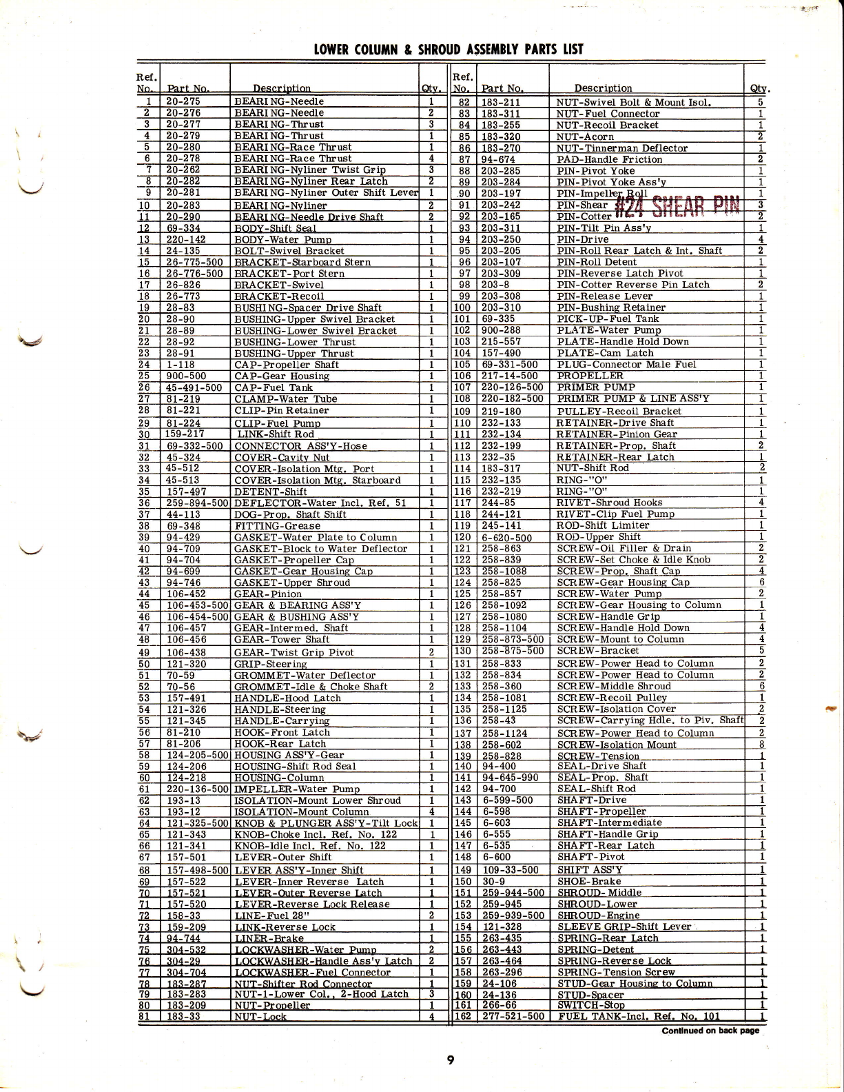
PROPELLER SHEAR PIN
The soft safety pin shears off when an obstruction is
struck at,high speed, thus protecting the gears and shafts from
damage. When shear pin is broken the engine will continue
to run, however, the propeller will not be rotating. To repair
shut off motor and remove propeller cotter pin and nut. Slip
off propeller and replace with new shear pin. Extra shear pins
and cotter pin are located under shroud on powerhead.
SOLID STATE IGNITION SYSTEM
(A) The solid state ignition system consists of the following compononF
parts: Flywheel, Ignition Module, Spark Plug, and S. . ;
Advance Assembly.
(B) Inspect the following if engine fails or is hard to start. ( I ) Spark plug
as often as necessary. Be sure spark plug gap setting is .025. (2)
Gasoline fuel supply air vent screw on filler cap at fuel tank should
be open. (3) Carburetor bcing starved of fuel.
(C) The correct spark plug for this motor is Champion J I 3Y or
equivalent.
(D) To test ignition system for spark remove high tension wire from
spark plug and hold about I / E' from any metal part of motor and
pull starter cord. If a spark bridges thc gap the ignition system is in
good operating condition. If no spark, have the ignition system
checkcd at a Authorizcd Servicc Ccntcr.
STORAGE \ /
To store your outboard drain all water from lowel /
umn and drain gas line and carburetor. Place motor c 's
side, remove spark plug and pour about l,/4 cup of oiL.-,/o
spark plug hole. Pull starter rope sever'al times to rotate the
crankshaft then replace spark plug. Fill gear housing with
grease as directed. Store in upright position. When starting a
new season always use fresh gasoline. Last. year's gasoline
may have vArnish deposits that will plug the carburetor jetg
thus requiring a carburetor overhaul.
(B)
4

\#'
Although interior surfaces of your outboard motor are designed
to resist corrosion, there still is a possibility of mechanical
build-up of salt and silt deposits. This can be eliminated only
by ftushing with fresh water. To materially increase the life
of all expoged parts and decorative finishes, follow these steps:
1. Always tilt your motor out of water when not in use.
2. Never leave the lower unit in salt water overnight.
3. Run outboard motor in fresh water tank for approximately
5 minutes to flush out salt deposits and to avoid possible
corrosion (see illustration),
4. l{ash engine down with fresh water and periodically apply
an automotive type wax to protect the finish.
5. Lubricate propeller shaft occasionally with a waterproof
type of lubricant (Lithium Grease), thus enabling the pro-
peller to be removed easily.
6. It is a good practice when operating in salt water to inspect
your motor daily and to apply a light coating of grease to
any part or area that shows evidence of corrosion or rust.
7. Always remove motor from boat vertically, allowing water
to drain from column before tilting the motor.
-XEEP WATER LEVEL APPROXIMATELY
I s rilcxrs FRoM ToP
I
OVERFLOW
DRAIN
?"x4"
MOUNTING BOARO
\*
CAUTION
Do not run your outboard motor out of water be-
cause it will damage the cooling system and engine'
To check out your motor at home, or flush it after
salt water use, obtain a S5-gallon drum with top
removed. fit it with a mounting board for your
motor, and fiII the drum to within 9" of top with
fresh water to serve as a test tank fol running your
motor. Make sure propeller is turning, but do not
exceed idle speed position. Do not readjust the
carburetor while running your motor in this type
of test tank. Run motor in a well ventilated area
or outside.
/"""i/* I i/si$
*"*/i'"lSlsliFr TROUBTE SHOOTING CHECK LIST
x x Remote Fuel Tank Not Connected - where opplicoble
xxFuel Tank Empty
xxXXFuel Line Kinked or Pinched
xxxFuel Filters Dirty or Clogged
xxXXVent Screw Gasket Obstructing Air Flow - Fuel Tonk
xXxVent Screw on Fuel Tank Cap Closed - Fuel Tonk
xxXx Air Leak in Engine
xx x Air Leak ln Fuel System
x x XxCarburetor Passages Clogged or Dirty
xxxx x lncorrect Fuel-Oil Mixture
xxxxxCarburetor Out of Adjustment
xEngine Flooded
xxx x xWrong Type Spark Plug
xxxXxDefective or Fouled Spark Plug
xDefective Magneto
xSpark Does Not Jump Spark Plug Gap
xEngine Out of Time
xxxxxWeak or Defective lgnition Transformer
xSpark Plug Lead Wire Not Secured
xxFrayed or Cracked Lead Wire !nsulation
xxDisconnected, Grounded or Loose Wiring in Electrical System
xPropeller Bound by Foreign Objects (Fishing Line, Weeds, Etc.)
xxWater Pump and Coolinq System Failure
5
f

POWERHTAD PARIS LISI
a-'-'-89
E
e__1 18
I
)
2r ' ,/ *^ s -\rE| -l
*/-ttt e5- (g 68\({2- ^ 6-11-_/_ |
o, --9,r"----r12
N r'o)) i (
2t
123 {) ._ O 5p*--;jz i;<
r -t- t r'a{ / 25
tr?-'^7ffi'1,'ffiffi
m+ mi *'?l],,'-\el' ,[T
tT.l -l t*I1_l a-
-*'d
76 rbr ,[o
$--5
,r{ I

POWTRHEAD PARIS TISI
Ref .
!6-
t1
48
2 19- 186-500 AINER-Dos Starter
REIAINER-Bear
RE'IAINER-Wrist Pin
BRACKET-Spare Pin PI
258-1t27
CONNECTOR-Elbow -Thrott1e Control Arm
OVER-Float Bowl
CRANKSHAFT 4-Adaptor to Shilt Linriter
DEFLECTOR-Cvlinder Head BRACKET-Shortins Wire
FLOAT & LEVER ASS'Y SCREW-Choke & Throttle Valve
l2]:r!-!l!-:!IS3l4
SCREW-Head
258-8?3-500 SCREW-Induction Bracket
-Brns. Plate to B
-Brns. Plate to Block
6- 614-500 SCREW-Idle Adi- Ass'
181-5-500 SCREW-Connectins Rod
SCREW-Recoil
L-Bearing Plate
HEAD-Cylinder
ASS'Y-Recoil
232-t37 SPARK PLUG-J13Y
-Starter Pawl
159-210
136- 147
SPRING-Carb- Float
268-36-500 MAGNETO ASS'Y
NUT-Shoulder Screw
WASHER-Thrrttle Arm
NUT-Carb. to Ind. Bracket
2 15-578-500
1
2
\J
\r
order By part Number, Not Reference Number. spEctFlcATloNs
BORE AND STROKE 2-5/8 x l-7/8
DISPLACEMENT (Cu. rn.) ------- --- 10.14
CARBTRETOR ---------- Float
CRANKSHAFT---------- Forged
BEARINGS (Engine) --------Needle and BaII
BEARINGS (Gear HousinC)---- ----Needle
GEAR RATIO ------ --- L3-22
PROPELLB TYPE --------- Shear Pin - Semi Weedless
PROPELLER, DIA. & PITCH -- 6-3/4x6-3/8
IDLE SPEED -.--- 9OO R. P. M"
OPMATION RANGE --. 4OOO . 5OOO R. P. M.
z PEAK HORSEPOM, --------At 6000 R" P.M. Sea Level

TOTIIER COLUIIN & SHROUD ASSETIBIY PARIS TISI
50
I127
i/
130
I 168
[/ 156 -rr8
v{--,,
113-$-
. __-.c
tr7
<-d>
- --'
I
\#
\./'
\
1OWM COUIII]I & SHROUD ASSIITB]Y PARIS TISI
IP-Pin Retainer
GASKET-BIoCk to Water Deflector SCREW-OiI Filler & Drain
SCREW-Water
LEVffi,-Outer Shift
9

towtR CotUftlH & sHRoUD ASSt[lBtY
Descr ir)t r ()n
TUtsE-Water
WASHm-Filler Hole
WASHER-Gear Housing to Column
ETAI NER-''X''
EW-Carrving Handle to PivASHffi.-Friction Notc
PARTS I.I5T
NOTE: ORDER BY PART NO., NOT REFERENCE NO.
MR. SALESI\{AN OR MR. DEALER: Please fill out this warranty form to insure
that your customer will receive warranty
service if needed.
Street Address or R. F. D. No. County
CLIN.T0N ENGINES C0RP0RATI0N o MAQU0KETA, l0WA
wa.E3.E3. ^rtfY
THERE ARE NO WARRANTIES WHICH EXTENO BEYOND THE PRODUCT OESCRIPTION EXCEPTING ONLY THAT
EAEij pnooucl soLD HEREUNoER ls wARRANTEo AS FoLLows:
ONE YEAR LIMITED WARRANTY
FOR ONE YEAR FROM PURCHASE, qLrNl'9Ir_E!-Gr!ErS COBeOR^TIq{, rvlL.L-REPLACE FOR THE ORIGINAL
FU'Cc-iiA-sent, FireE or CnancE, ANY PART qBroABls,-Equryg_uf-ory qx-AMlNArloN BY ANY FA6T6RY
icJiiijHiieD'senvrce eccouNr., oR By FAcroRy, AI M^auq[ETA-, !o_w.! To BE DEFEcrlvE lN MATER-
iir-f iji i^ionrua_Nsrrip on BoTH, ALL 1RANIPqtTATION CHARGES ON PARTS SUBMITTED FOR REPLACE-
i',iiNi iJr'ioER rxii wnRRaurY MUST FE BoRNE BY PURcHASER
ixene ts No orHER ExPREss wARRANTY.
il,iFAiEd wnnnANTIes, INCLUoING THOSE OF MERCHANTABILITY ANO FITNESS FOR A PARTICULAR PUR.
ij.iisE. [ne LIMITED To oNE YEAR FRoM PURCHASE AND TO THE EXTENT PERMITTED BY LAW ANY AND
iil_rr.irpIleo WARRANTIES ARE EXCLUDED. THIS IS THE EXCLUSIVE REMEDY ANO LIABILITY FOR CON-
SEQUENTIAL DAMAGES UNDER ANY AND ALL IVARRANTIES ARE EXCLUDED TO THE EXTENT EXCLUSION
IS PERMITTED BY LAW.
Outboard - Warranty Period One Year
C LII,ITON ENGINES CORPORATION
Maquoketa, Iowa
WARRANTY PROCEDIJRE
Outboard Model No. (Copy No. from Outboard name plate) Outboard Serial No.
Date Purchased
MR. CUSTOMER:
Purchased From
Should warranty service be required, present this completed
warranty form to your Authorized Clinton Service Account
along with outboard.
City State
This manual suits for next models
1


