Clinton AS-870 User manual

CLINTON
MODEL AS-870 / 870LCD
VARIABLE SPEED
DC SERVO MOTOR
NEEDLE POSITIONER THREAD TRIMMER
NEEDLE COOLER
SERVICE MANUAL

TABLE OF CONTENTS
SECTION I - INTRODUCTION . . . . . . . . . . . . . . . . . . . . . . . . . . . . . . . . . . . . . . 1-1
SECTION II - INSTALLATION . . . . . . . . . . . . . . . . . . . . . . . . . . . . . . . . . . . . . . 2-1
A.
B.
C.
D.
E.
F.
G.
CONTROL BOX TO MOTOR . . . . . . . . . . . . . . . . . . . . . . . .
MOTOR . . . . . . . . . . . . . . . . . . . . . . . . . . . . . . . . . . . . . . . .
SYNCHRONIZER . . . . . . . . . . . . . . . . . . . . . . . . . . . . . . . . .
LCD DISPLAY . . . . . . . . . . . . . . . . . . . . . . . . . . . . . . . . . . . .
SWITCH BOX . . . . . . . . . . . . . . . . . . . . . . . . . . . . . . . . . . . .
POWER AND CABLE CONNECTIONS . . . . . . . . . . . . . . . . .
MOTOR ROTATION . . . . . . . . . . . . . . . . . . . . . . . . . . . . . . .
2-1
2-1
2-2
2-2
2-2
2-3
2-3
SECTION III - SYNCHRONIZER TIMING . . . . . . . . . . . . . . . . . . . . . . . . . . . . . . . 3-1
A. UNDERTRIMMER . . . . . . . . . . . . . . . . . . . . . . . . . . . . . . . . . 3-1
SECTION IV - CONTROL BOX ADJUSTMENTS . . . . . . . . . . . . . . . . . . . . . . . . . 4-1
A. MAXIMUM SEWING SPEED. . . . . . . . . . . . . . . . . . . . . . . . . . 4-1
SECTION V - PROGRAMMABLE LCD DISPLAY . . . . . . . . . . . . . . . . . . . . . . . 5-1
A.
B.
C.
D.
E.
DIRECT ACCESS PARAMETERS . . . . . . . . . . . . . . . . . . . .
HIDDEN PARAMETERS . . . . . . . . . . . . . . . . . . . . . . . . . . .
MASTER RESET . . . . . . . . . . . . . . . . . . . . . . . . . . . . . . . . .
PULLEY RATIO . . . . . . . . . . . . . . . . . . . . . . . . . . . . . . . . .
TEST PROGRAM . . . . . . . . . . . . . . . . . . . . . . . . . . . . . . . . .
1. TREADLE TEST. . . . . . . . . . . . . . . . . . . . . . . . . . . . . . . . .
2. SYNCHRONIZER TEST . . . . . . . . . . . . . . . . . . . . . . . . . .
3. ENCODER TEST. . . . . . . . . . . . . . . . . . . . . . . . . . . . . . . .
4. DIVIDER TEST. . . . . . . . . . . . . . . . . . . . . . . . . . . . . . . . .
5-1
5-3
5-3
5-3
5-4
5-4
5-4
5-4
5-4
SECTION VI - CONNECTOR DIAGRAMS . . . . . . . . . . . . . . . . . . . . . . . . . . . . . . 6-1
SECTION VII - DRAWINGS AND PARTS LIST . . . . . . . . . . . . . . . . . . . . . . . . . . . 7-1
A.
B.
C.
D.
E.
F.
G.
H.
MAJOR ASSEMBLIES . . . . . . . . . . . . . . . . . . . . . . . . . . . . . .
MOTOR ASSEMBLY, DC SERVO . . . . . . . . . . . . . . . . . . . . .
CONTROL BOX ASSEMBLY . . . . . . . . . . . . . . . . . . . . . . . . .
POWER SUPPLY . . . . . . . . . . . . . . . . . . . . . . . . . . . . . . . .
SYNCHRONIZER . . . . . . . . . . . . . . . . . . . . . . . . . . . . . . . . . .
PROGRAMMABLE DISPLAY . . . . . . . . . . . . . . . . . . . . . . . . .
MISCELLANEOUS PARTS . . . . . . . . . . . . . . . . . . . . . . . . . .
E-PROM . . . . . . . . . . . . . . . . . . . . . . . . . . . . . . . . . . . . . . . .
7-1
7-2
7-4
7-5
7-6
7-7
7-7
7-8
ML870LCD-2A

SECTION I ML870LCD-3A
INTRODUCTION
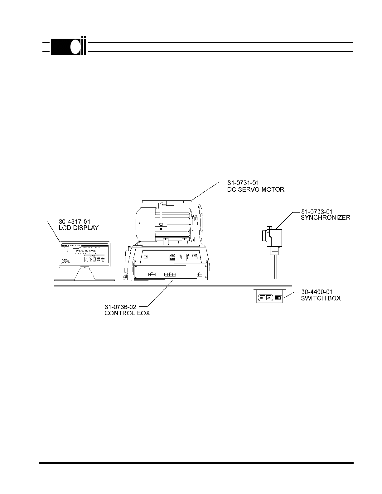
Clinton's Model 870LCD is an electronically controlled variable speed drive for industrial sewing
machines. The drive consists of a brushless DC Servo Motor, controller with a microcomputer,
synchronizer, speed control and programmable LCD display. No clutches or brakes are used. All
components interact to give a fast accurate and reliable sewing machine drive. The components
of the system are shown are shown in figure below.
The model 870LCD has outputs for a trimmer, footlift, wiper and needle cooler. It can be used to
operate all Clinton trimmers, as well as the Singer, Union Special, Pfaff, Juki, Brother
undertrimmers and chain stitch machines.
The programmable LCD display is used to select the trimmer type and other parameters.
See section V.
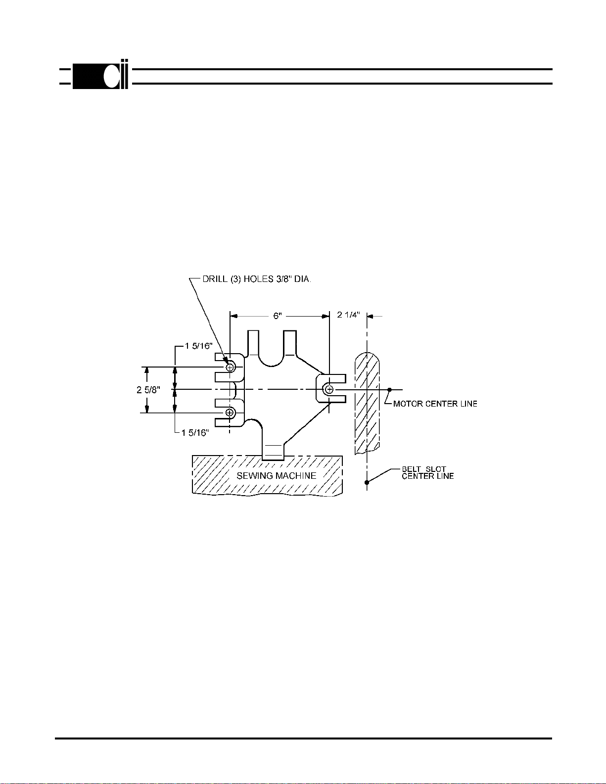
MOTOR INSTALLATION
FIG. 2-1
INSTALLATION
A. CONTROL BOX TO MOTOR
Refer to the control box assembly parts drawing in figure 7-3. Attach the mounting brackets to
the control box then, mount the control box to the motor with the hardware provided.
B. MOTOR
1. Drill three holes in the sewing machine table as shown in figure 2-1.
2. Mount the motor to the table using the spacers, carriage bolts, nuts, washers, and flanged
spacers supplied (See Figure 7-2). Install pulley and belt then check the following:
a. The motor is mounted so that the motor drive pulley and sewing machine drive pulley
are properly aligned.
b. The V-belt connecting the motor to the sewing machine should be tensioned properly.
It should be possible to pull a correctly tensioned belt together between two
fingers within approximately 2 cm (3/4"). Excessive tension may not onlyshorten the
life of the bearings, but could also affect the operation of the sewing machine. A loose
belt will affect positioning accuracy.
c. Install the belt guard.
2-1
ML890-7A
SECTION II
®
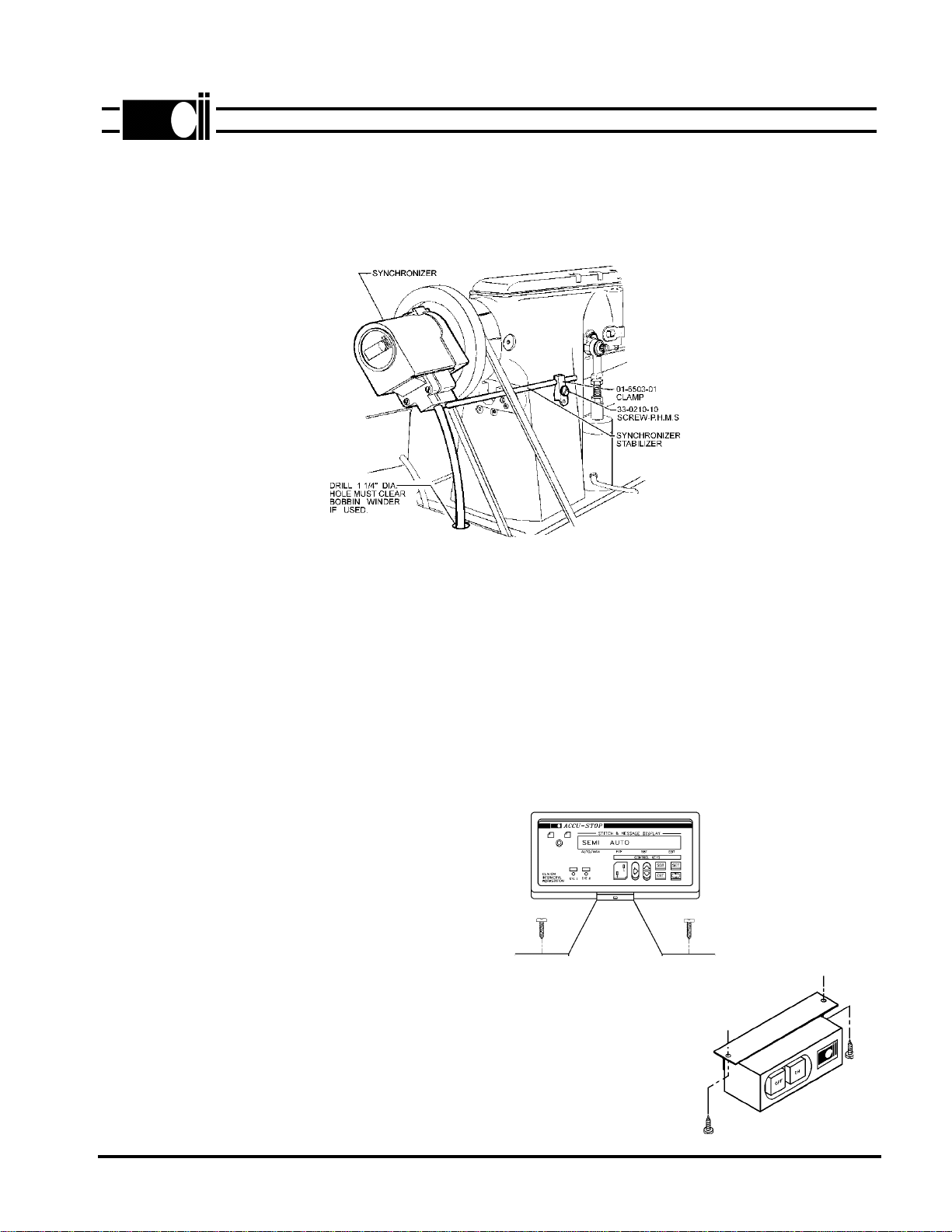
C. SYNCHRONIZER
Two methods are used to attach the synchronizer to the handwheel. They are (1) handwheel turned down to
accept synchronizer and (2) an adapter that is mounted to a machined handwheel.
Refer to figure 2-2 and install the synchronizer as follows:
SYNCHRONIZER INSTALLATION
UNIVERSAL MOUNT
FIG. 2-2
1. Install adapter if used.
2. Mount and secure synchronizer to handwheel or adapter.
3. Position the synchronizer retaining rod and clamp as shown in figure 2-2. Make sure that the rod
clears the sewing machine belt.
4. Using the mounting clamp hole as a guide, drill and tap a 10-32 hole in the machine casting. Secure
clamp and rod with a 10-32 X 1/2 B.H.M.S.
5. Drill a 1-1/4" Dia. hole in table to route synchronizer cable to logic box. Check that cable has adequate
slack when tilting machine for service.
D. LCD DISPLAY
Mount the LCD display console at a
convenient location on the table top
as shown in figure 2-3. Route cable
through same hole that synchronizer
cable passes through.
E. SWITCH BOX
Install switch box at a convenient
location under the table.
See figure 2-4.
2-2
ML890-8A
®
FIG. 2-3
FIG. 2-4
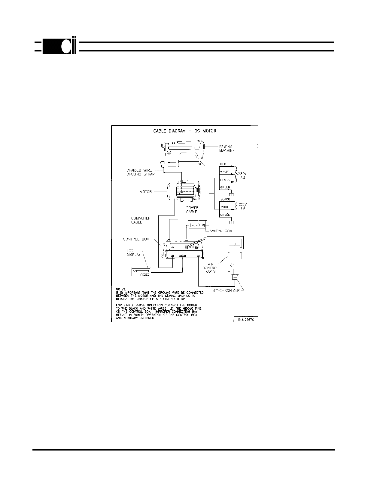
F. POWER AND CABLE CONNECTIONS
Refer to figure 2-5 and connect all cables as shown. The system can be operated from 230V, 3
phase or 230V, single phase power. See figure 2-5.
Caution: It is important that the ground wire be connected between the motor and sewing
machine to prevent a static charge buildup at the sewhead.
2-3
G. MOTOR ROTATION
Temporarily remove the "V" belt. Turn power on then move the pedal forward and
note the direction of motor pulley rotation. If incorrect, do the following:
1. Turn power off.
2. Refer to section V-B, Hidden Parameters, and follow the instructions to change
motor rotation. The parameter is in the "**** Toggle Switches" group.
3. Install the "V" belt.
FIG. 2-5
ML890-9B
®

SYNCHRONIZER TIMING
Turn the power off before making synchronizer adjustments. Refer to figure below for all adjust-
ments and perform the steps below to time the synchronizer.
1. Remove cover from synchronizer, then loosen the disc locking screw.
2. Rotate the handwheel so that the take up during the rising portion of its cycle is
approxiamately 1/16" below its highest position.
3. Rotate the UP sensor disc until the notch is centered in the photo interrupter module.
4. Turn the handwheel until the needle is positioned down.
5. Rotate the down sensor disc until the notch is centered in the photo interrupter module.
6. Rotate the handwheel until the needle thread is positioned between 6 and 7 o'clock around
the bobbin case. Rotate the trim disc until the notch is centered in the photo interrupter
module.
7. Tighten the disc locking screw and replace the cover.
NOTE: After power is turned on a fine adjustment may be necessary and can be made by
positioning the needle under power and noting the actual needle UP and needle DOWN
and 6 o'clock stopping positions. If any of the positions are not correct, readjust the
appropriate disc.
3-1
SECTION III
®
ML890-
10A

A. MAXIMUM SEWING SPEED
Maximum sewing speed can be adjusted by changing the "MAXIMUM SPEED" parameter in the
"LCD" display (see section V).
4-1
®
ML870LCD-8B
SECTION IV
CONTROL BOX ADJUSTMENTS

SECTION V ML870LCD-4A
PROGRAMMABLE LCD DISPLAY
The LCD display, shown in fig. below is used to program and set the various parameters of the
870LCD; SPEEDS, TIMERS, COUNTERS, and TOGGLE SWITCHES.
Two (2) different modes of operation are
available. They are:
1. Operating Mode
2. Programming Mode
When power is turned on, the display
is in the operating mode.
There are two (2) groups of parameters that are accessed in different ways. They are : (1) param-
eters with direct access and (2) hidden parameters with indirect access. In addition a master reset
is available to reset all parameters to their default values.
A. DIRECT ACCESS PARAMETERS
The direct access parameters are divided into four (4) groups. They are (1) SPEEDS, (2)
TIMERS, (3) COUNTERS, and (4) TOGGLE SWITCHES. Table 5-1 describes each parameter,
shows the default value and range of adjustment for each parameter.
To change a parameter, follow the sequence described below.
1. Press the key to enter the programming mode. Continue pressing this key until the
parameter group that is to be changed is displayed. As an alternative; press the key to enter
the programming mode and display the last changed parameter.
2. Press the key to step to the next parameter in the selected group.
3. Press the key to increase or the key to decrease the contents of the displayed
parameter. Both keys are used to toggle parameters between states in the Toggle Switches
group. Hold the key closed to make the display step automatically.
4. Press the key to return to the operating mode.
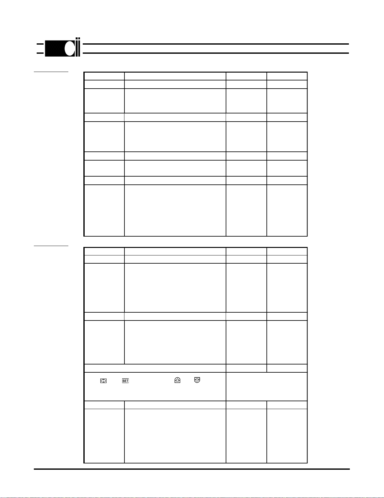
TABLE 5-1
TABLE 5-2
®
ML870LCD-9
PARAMETER DESCRIPTION DEFAULT RANGE
****SPEEDS RPM RPM
TRIM
MAXIMUM
Machine speed during the position trim cycle.
If *** Tgl switch "position" is set to w/ramp the
"trm/pos" speed affects the slope of the ramp.
If "no ramp" is selected, position speed is
constant and can be changed by the "trim/pos"
parameter
Maximum sewing machine speed. The speed
cannot go higher than 3500 times the pulley
ratio
220
4200
100-400
8000
****MISCELLANEOUS
HYSTERESIS
PF DUTY
T.BK.DEL
The amount the pedal has to be moved when
going from one direction to the other before the
speed changes.
Average voltage applied to Pr. Ft. solenoid. The
voltage should be high enough to keep the
solenoid energized without overheating.
Delays reversing of motor until the trim cycle is
finsished. See "TURNBAK" parameter.
3
3
10
1-10
2-10
3-15
SELECT TRIM SYSTEM
Press then keys first, then use or keys
to select one of the following trimmers, NO TRIM SYS, CLINTON
LOCKST, JUKI/DURKOPP, PFAFF MECH, BROTH/PFAFF PN,
SINGER/UNION, CLINTON T & B TRIM or CHAIN ST.
CLINTON
LOCKSTITCH
****TOGGLE SWITCHES
DIRECTION
POSITION
AFTER TR
SAFETY SW
SAFETY SW SEW
Direction of motor rotation viewed from pulley.
Select position with ramp or position at constant
position speed.
Not used in this system.
Set to enable only on machine with trimmer
safety sw. If enabled, machine will not run
unless safety switch is properly connected.
Set to CLS if safety switch is closed while
sewing or OPN if switch is open while sewing.
OFF
CONTINUE
DISABLE
CLS
ON/OFF
CONTINUE/
PED. NEUT.
ENABLE/
DISABLE
CLS/OPN
5-2
PARAMETER DESCRIPTION DEFAULT RANGE
SPEED GROUP RPM RPM
MINIMUM
SLOW STRT First speed when pedal is moved forward.
Initial speed at start of cycle (after trim).
This speed is maintained for No. of stitches set
by soft start count parameter.
180
500
80-400
150-1000
TIMER GROUP MS MS
STRT DEL
TRM TIME
WIPER TIME
Delays machine start to allow presser foot to
drop.
Clinton Lockstitch- Time machine stops at
6 o'clock position to pick up threads.
Wiper Pulse time.
120
80
80
10-500
10-1000
0-1000
COUNTER GROUP STITCHES STITCHES
SOFT ST Number of stitches sewn at soft start speed
after trim (EOC). 31-25
TOGGLE SWITCHES
PF/SEAM
PF/EOC
SOFT STRT
HEEL 2
TURNBAK
POSITION
Pr. Ft. UP or DOWN in seam, treadle neutral.
Pr. Ft. UP or DOWN after trim, treadle neutral.
Used to turn soft "ON" or "OFF".
If "ENABLED", trims with heel 2. If "DISABLED"
no trim with heel 2.
If "ON", machine rotates in reverse direction
after trim, to move needle to its highest position.
Selects the needle position in the seam to "UP"
or "DOWN".
DOWN
DOWN
OFF
ENABLED
OFF
DOWN
UP/DOWN
UP/DOWN
ON/OFF
ENABLE/
DISABLE
ON/OFF
UP/DOWN

5-3
B. HIDDEN PARAMETERS
The parameters in this section are separated from the Direct Access parameters because they are
infrequently changed and should not be changed by the operator. The parameters are listed in
table 5-2.
1. Turn power off, if it is on, then wait until the display goes blank.
2. Press the key and the key simultaneously. Keep pressed then,
3. Turn power on. A series of "***" will appear on the display. They will slowly dissapear.
4. Release the keys then press the key before all the stars dissapear.
5. Press the key repeatedly, until the first hidden parameter group (****SPEEDS) is
diplayed. Note that 4 stars (*) as described in section "A" above.
®
ML870LCD-5A
C. MASTER RESET
In some cases it may be necessary to reset all parameters to their default values. This is done as
follows:
1. Turn power off, if it is on, then wait until the display goes blank.
2. Press the key, key and key simultaneously. Keep pressed then,
3. Turn power on. The display alternates between "Push Set" and "For Reset".
4. Push the key within 10 cycles.
5. The word "Programming" is displayed. The parameters will be reset to their default values
after a few seconds.
D. PULLEY RATIO (RATIO BETWEEN MOTOR AND MACHINE PULLEYS)
During the initial setup and after power is first turned on. The pulley ratio must be calculated. The
pedal must be moved to the maximum forward position to do this. While the ratio is being taken,
the machine speed is limited for several stitches. After the ratio is taken, the machine will then
accelerate to maximum speed.
Each time power is turned off then back on, the ratio is checked when the pedal is moved forward
the first time. If the ratio has changed, because of a pulley change, then the ratio will be recalcu-
lated. The ratio can be displayed by pressing the and keys simultaneously. If the ratio is
correct, a star (*) will be displayed after the ratio number.
E. TEST PROGRAM
A test program is available to test the treadle, synchronizer, encoder, and divider for proper
operation. To select the program, press the and keys simultaneously. The display will
show "SYSTEM TEST". Press the key to toggle between each test, i.e. Treadle,
Synchronizer, Encoder, or Divider. Press the key to activate whichever test is selected.
1. Treadle Test
Press the button until "TEST TREADLE" is displayed. Press the button once. The
display should show "NEUTRAL".
a. Move the pedal from neutral to heel 1 then to heel 2.
The display should show each position.
b. Move the pedal forward slowly. As the pedal is moved, a number (0 to 255, see NOTE#4)
will be displayed.
This number is proportional to how far the pedal is moved. The lowest number should be
no more than "8" and the highest number greater than "250".
(NOTE: the maximum speed pot should be in the full cw position.)
c. Press the pedal full forward. Turn the maximum speed pot ccw. The displayed count
should decrease as the pot is turned. Return the pot to its maximum cw position.
2. Synchronizer Test
Press the button. The display will read "TEST SYNCHRONIZER". Press the button.
Rotate the machine pulley by hand. The display will show the position. The positions are as
follows: "UP", "DOWN", and "TRIM".
3. Encoder Test
CAUTION: Remove sewing machine belt. The belt has to be removed because the motor
may not develop sufficient torque to turn the machine.
Press the button. The display will read "TEST ENCODER". Press the button. The
display will read "PUSH TREADLE". Press the pedal fully forward for approximately three
seconds then release the treadle. Do not heel. The result will be displayed, either "OK" or
"NOT OK".
Heel the pedal. The display shows the number of counts. The number should be between
795 and 800 pls.
4. Divider Test
NOTE: This test will not function properly if the encoder test fails. Also remove sewing ma
chine belt.
Press the button, the display will read "TEST DIVIDER". Press the button. The
displayreads "PUSH TREADLE". Press the treadle fully forward for 3 seconds, then release
the treadle. If the test works the display will read "DIVIDER OK". If the test fails the display will
show the test which failed, ie. "PASS 1", "PASS 2", "PASS 3", "PASS 4", "PASS 5", or "PASS
6” .
5-4
®
ML870LCD-10
CONNECTOR DIAGRAMS
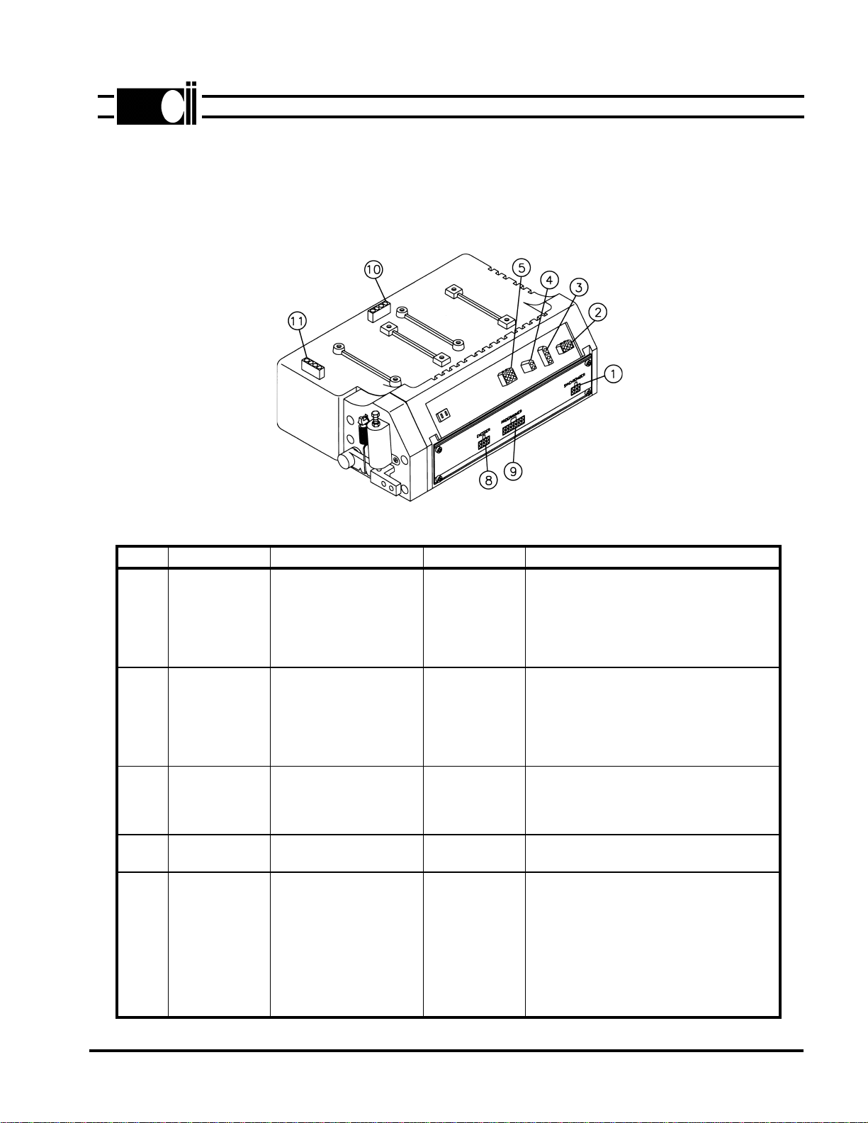
Listed below are the pinouts for the model AS 870LCD control box connectors.
6-1
NO. TOTAL PINS CONNECTOR PIN NO. FUNCTION
1 6 SYNCHRONIZER 1
2
3
4
5
6
+5
DOWN SENSOR
UP SENSOR
TRIM SENSOR
GND
LED
2 6 AUX INPUTS 1
2
3
4
5
6
+5
GND
CHASSIS GND
I 1
I 2
I 3
3 4 AUX OUTPUTS 1
2
3
4
+48 V
R1
+48 V
R2
4 2 FOOTLIFT 1
2FOOTLIFT SOL.
+48V
5 9 TRIM, WIPER, NEEDLE
COOLER, AND SAFETY
SWITCH
1
4
2
5
3
6
7
8
9
WIPER SOL. -
WIPER SOL. +(48V)
TRIMMER SOL. -
TRIMMER SOL. +(48V)
NEEDLE COOLER +
NEEDLE COOLER -
+5V OR +10V
SAFETY SWITCH (GND)
SAFETY SWITCH (NO)
®
ML870LCD-6A
SECTION VI

6-2
NO. TOTAL PINS CONNECTOR PIN NO. FUNCTION
8 8 COMMUTATOR 1
2
3
4
5
6
7
8
+5V
ENCODER (S1)
ENCODER (S2)
SIG. GND
PHASE C
PHASE B
PHASE A
-5V
916 LCD DISPLAY 1
2
3
4
5
6
7
8
9
10
11
12
13
14
15
16
EXT1
CHASSIS GND
+5V
GND
D0
D1
D2
D3
D4
D5
D6
D7
CA1
E
ERD
CA0
10 4AC POWER 220V 3 1
2
3
4
PHASE A
PHASE B
PHASE C
CHASSIS GND
1 1 4MOTOR VOLTAGE 1
2
3
4
PHASE A
PHASE B
PHASE C
CHASSIS GND
®
ML870LCD-11
DRAWINGS AND PARTS LIST
MODEL 870LCD
81-0752-02
7-1
A. MAJOR ASSEMBLIES
®
ML870LCD7ASECTION VII
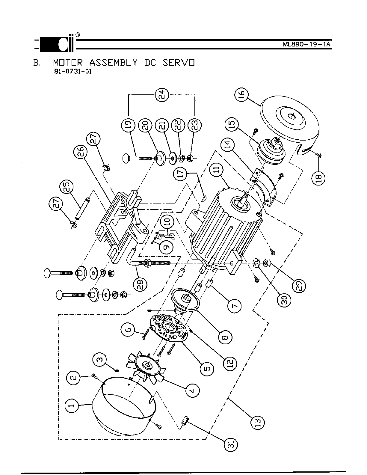
ITEM DESCRIPTION PART NO. QUANTITY
1
2
3
4
5
6
7
8
9
10
11
12
13
14
15
16
17
18
19
20
21
22
23
24
25
26
27
28
29
30
31
COVER
SCREW
SCREW, S.S.S.
FAN
PC BOARD, ENCODER
SCREW
SPACER
ENCODER DISC
SCREW
ENCODER SENSOR
MOTOR, DC
SCREW, S.S.S.
MOTOR/ENCODER ASSEMBLY
BELT GUARD, FIXED
PULLEY - 50MM
PULLEY - 60MM
PULLEY - 65MM
PULLEY - 70MM
PULLEY - 75MM
PULLEY - 80MM
PULLEY - 85MM
PULLEY - 90MM
PULLEY - 95MM
PULLEY - 100MM
PULLEY - 105MM
PULLEY - 110MM
PULLEY - 115MM
PULLEY - 120MM
PULLEY - 125MM
PULLEY - 130MM
PULLEY - 140MM
PULLEY - 150MM
BELT GUARD, ADJUSTABLE
KEY, PULLEY
SCREW M5 X 10 HEX HD.
BOLT, CARRAIGE
SPACER
WASHER, FLAT
WASHER, SPLIT LOCK
NUT, HEX
HARDWARE KIT, MOTOR MOUNT
PIN
BRACKET, MOTOR MOUNT
SNAP RING
BOLT, ADJUSTING
NUT, HEX
WASHER, SPLIT LOCK
GROMMET
30-4433-01
30-4434-01
30-4435-01
30-4436-01
30-4437-01
30-4438-01
30-4439-01
30-4440-02
30-4441-01
30-4442-01
30-4443-01
30-4444-01
81-0732-01
30-4445-01
30-4204-50
30-4204-60
30-4204-65
30-4204-70
30-4204-75
30-4204-80
30-4204-85
30-4204-90
30-4204-95
30-4204-100
30-4204-105
30-4204-110
30-4204-115
30-4204-120
30-4204-125
30-4204-130
30-4204-140
30-4204-150
30-4203-01
30-4227-01
30-4206-01
30-4298-01
30-4332-01
30-4300-01
30-4301-01
30-4229-01
30-4337-01
30-4219-01
30-4446-01
30-4220-01
30-4205-01
30-4210-01
30-4218-01
30-4472-01
1
3
2
1
1
3
3
1
1
1
1
2
1
1
1
1
1
1
1
1
1
1
1
1
1
1
1
1
1
1
1
1
1
1
2
3
3
3
3
3
1
1
1
1
1
1
1
1
MOTOR ASSEMBLY PARTS LIST, DC SERVO
81-0731-01
7-3
®
ML890-19-2C

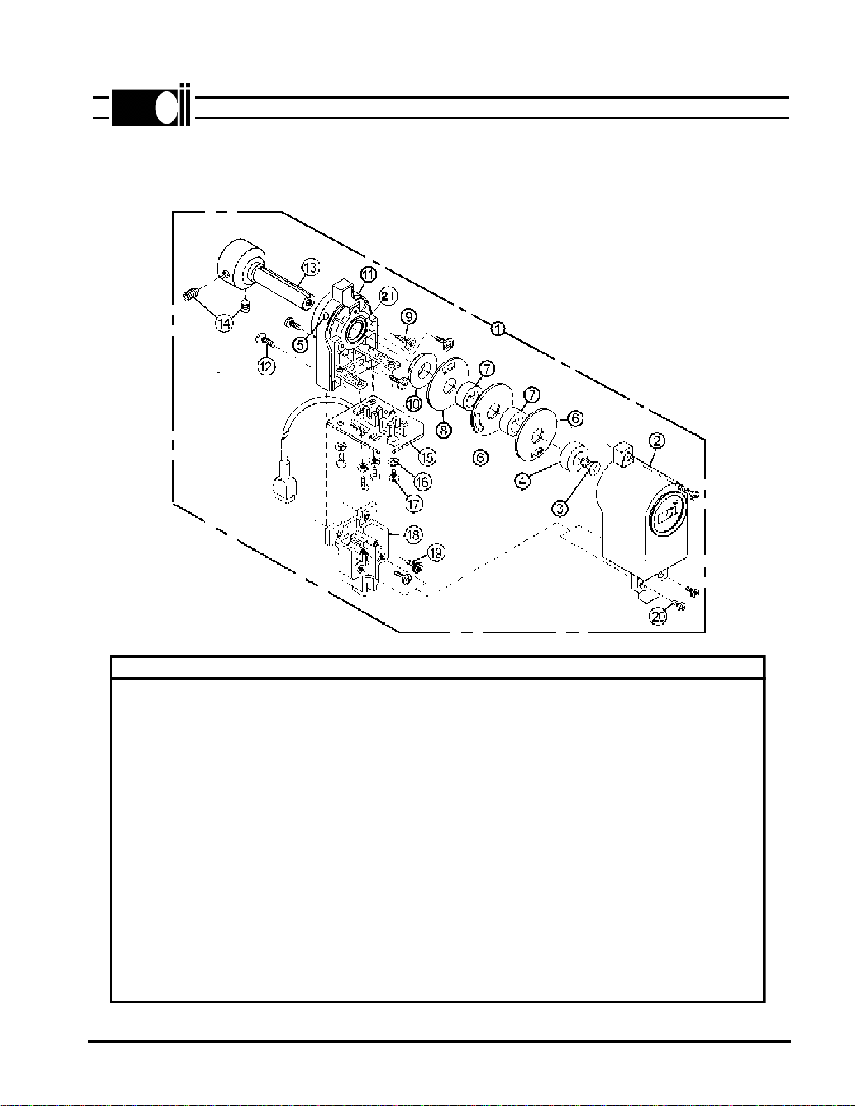
E. SYNCHRONIZER
7-6
ITEM DESCRIPTION PART NO. QUANTITY
1
2
3
4
5
6
7
8
9
10
11
12
13
14
15
16
17
18
19
20
21
SYNCHRONIZER
COVER, SYNCHRONIZER
SCREW M5 X 12 F.H.M.S.
SPACER DISC RETAINING
LED
DISC POSITIONER
SPACER, DISC
DISC, TRIM
SCREW M3.5 X SELF TAP
SPACER
HOUSING
SCREW M4 X 10
SHAFT, SYNCHRONIZER
SCREW M6 X 8 S.S.S.
PC BOARD, SYNCHRONIZER
SCREW, PC BOARD MOUNT
WASHER, SPLIT LOCK
BASE
SCREW M3 X SELF TAP
SCREW M3 X 10
BEARING
81-0733-01
30-4262-02
30-4263-01
30-4264-01
30-4428-01
30-4266-01
30-4267-01
30-4268-01
30-4270-01
30-4271-01
30-4272-02
30-4273-01
30-4429-01
30-4275-01
30-4430-01
30-4209-01
30-4277-01
30-4278-02
30-4279-01
30-4280-01
30-4281-01
1
1
1
1
1
2
3
1
3
1
1
2
1
2
1
4
4
1
2
2
1
®
ML890-20A
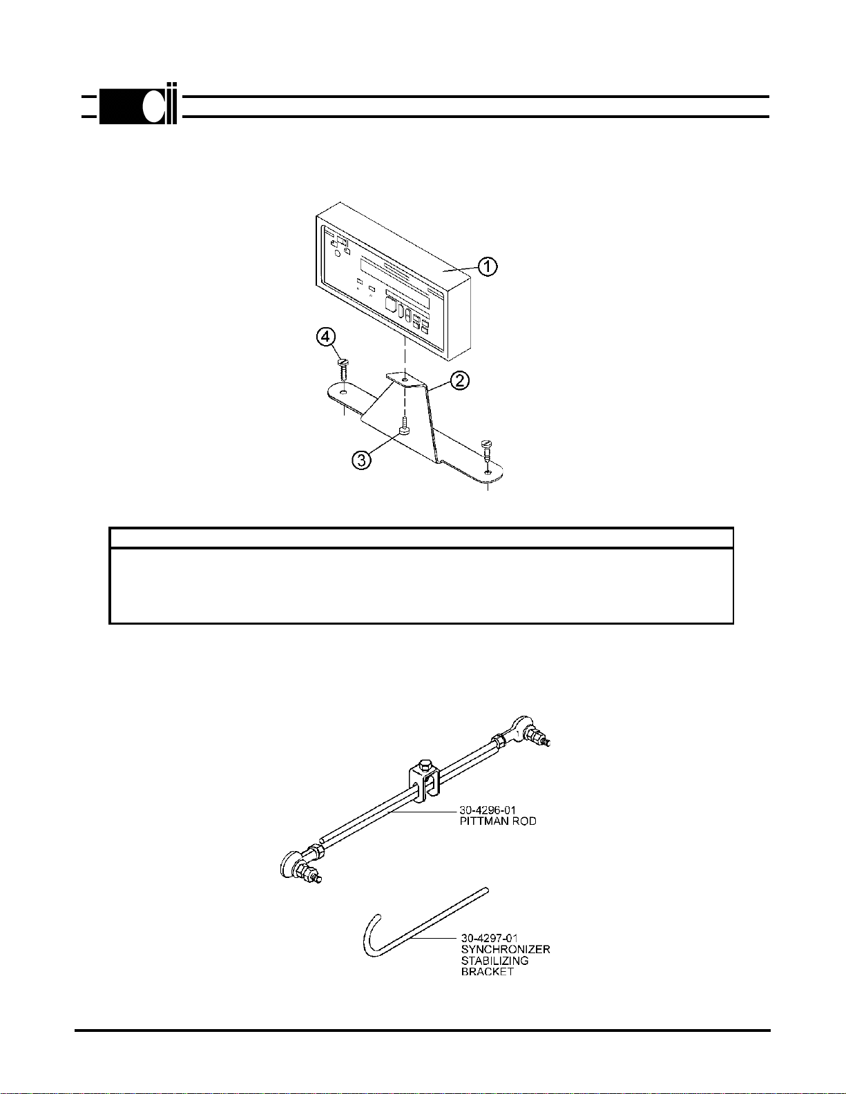
F. PROGRAMMABLE DISPLAY
G. MISCELLANEOUS PARTS
7-7
ITEM DESCRIPTION PART NO. QUANTITY
1
2
3
4
PROGRAMMABLE DISPLAY
PROGRAMMABLE DISPLAY
BRACKET, MOUNTING
SCREW M4 X 12
SCREW
30-4321-01 (890)
30-4317-01 (870LCD)
30-4286-01
30-4287-01
30-4288-01
1
1
1
1
2
®
ML890-21A
This manual suits for next models
1
Table of contents


