CNET CWP-854 User manual

Wireless-GPCIAdapter
User’sManual

TableofContents
1. Introduction
1.1The Wireless-G PCI Adapter
1.2 Key Features
2. Planning Your Wireless Network
2.1 Network Topology
2.2 Ad-Hoc versus Infrastructure Mode
3. Getting to Know the Wireless-G PCI Adapter
4. Installing Driver, Configuration Utility and Hardware for Windows 98SE/ME/2000/XP
5. Using the Configuration Utility in Windows 98SE/ME/2000/XP
5.1 Overview
5.2 Access the Configuration Utility
5.3 Profile
5.4 Create a New Profile
5.5 Link Status
5.6 Site Survey
5.7 Statistics
5.8 Advanced
5.9 About

1.Introduction
1.1 The Wireless-G PCI Adapter
The Wireless-G PCI Adapter can be installed in most desktops and provides true flexibility by
allowing the computer to be positioned almost anywhere in the building without the cost and
hassle of running network cables. Using the wireless PCI adapter, you don't have to worry about
drilling holes in your walls and climbing through the attic or cellar to get connected to the network.
Once installed and connected, you can keep in touch with friends and work through e-mail,
instant messaging and chat rooms as well as sharing files and other network resources such as
printers and network storage with other computers.
The Wireless-G PCI Adapter connects to 802.11g networks at an incredible speed of 54Mbps and
for added versatility; it can also interoperate with all Wireless-B (802.11b) products found in
homes, businesses, and public wireless hotspots around the country. In either mode, wireless
communications are protected by WEP and advanced WPA encryption levels.
1.2KeyFeatures
◆5 Times Faster and seamless operation with existing Wireless-B networks
◆64/128-bit WEP and WPA/WPA2 (Wi-Fi Protected Access) Encryption Provides Maximum
Wireless Security
◆Ease of Use through a Simple Setup Wizard
◆Compatible with Windows 98SE/ME/2000/XP

2
2.1 Network Topology
A wireless local area network (WLAN) is exactly like a regular local area network (LAN), except
that each computer in the WLAN uses a wireless device to connect to the network. Computers in
a WLAN share the same frequency channel and SSID, which is an identification name for
wireless devices.
2.2 AD-Hoc versus Infrastructure Mode
An Ad-Hoc wireless LAN is a group of computers, each equipped with one WLAN adapter,
connected as an independent wireless LAN. Computers in a specific Ad-Hoc wireless LAN
must all be configured to share the same radio channel.
An integrated wireless and wired LAN is called an Infrastructure configuration. In this mode, a
group of wireless nodes and an Access Point compose a Basic Service Set (BSS). Each wireless
node in a BSS can talk to any computer in the wired LAN infrastructure via the Access Point.

3.GettingtoKnowtheWireless-GPCI
adapter
Wireless-G PCI Adapter installs into desktops like any other PCI Adapter. The two indicator lights
on the mounting bracket of the card are:
Ready LED Green. The Ready LED will light up when the card links to a wireless device.
ACT LED Green. The ACT LED will blink when the card transmits/receives data.
4.InstallingDriver,ConfigurationUtilityand
HardwareinWindows98SE/ME/2000/XP
4.1 Driver Installation for Windows 98SE/ME/2000/XP
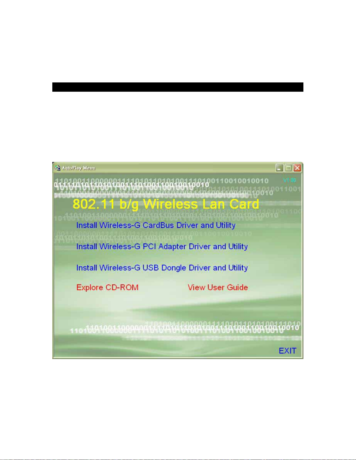
4.1.1 Running the Auto Install CD
Before installing your Wireless-G PCI Adapter, insert the Auto-Install CD into your
CD-ROM drive. Unless you have disabled the auto-run feature of Windows, the screen
shown in Fig 4-1 should appear automatically. If not, you can manually access the
installation by clicking the Start button and choosing Run. In the drop-down box type
D:\Setup.exe (where D: is the drive letter for your CD-ROM drive).
Alternately, double-click My Computer and double-click on the CD drive (Setup.exe) icon.
Fig 4-1
4.1.2 Click Install Wireless-G PCI Adapter Driver and Utility to install driver/utility for your
Wireless-G PCI Adapter. Click Yes >. ( Fig 4-2)
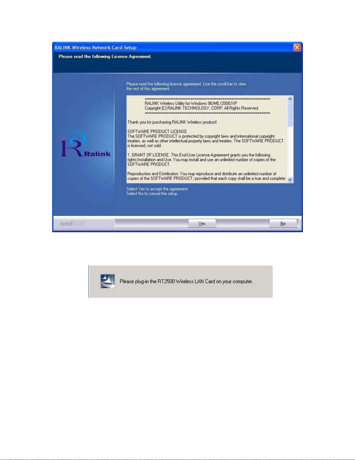
Fig 4-2
4.1.3 During the installation, a message pops up asking for the wireless card to be plugged in
(Fig 4-3). Please ignore this message and proceed to the next step.
Fig 4-3
4.1.4 In Windows XP and 2000 click Finish (Fig 4-4) to complete the installation.
When installing in Windows ME and 98SE, select Yes, I want to restart my computer
now and Finish (Fig 4-5) to complete the installation. The system will restart
automatically.
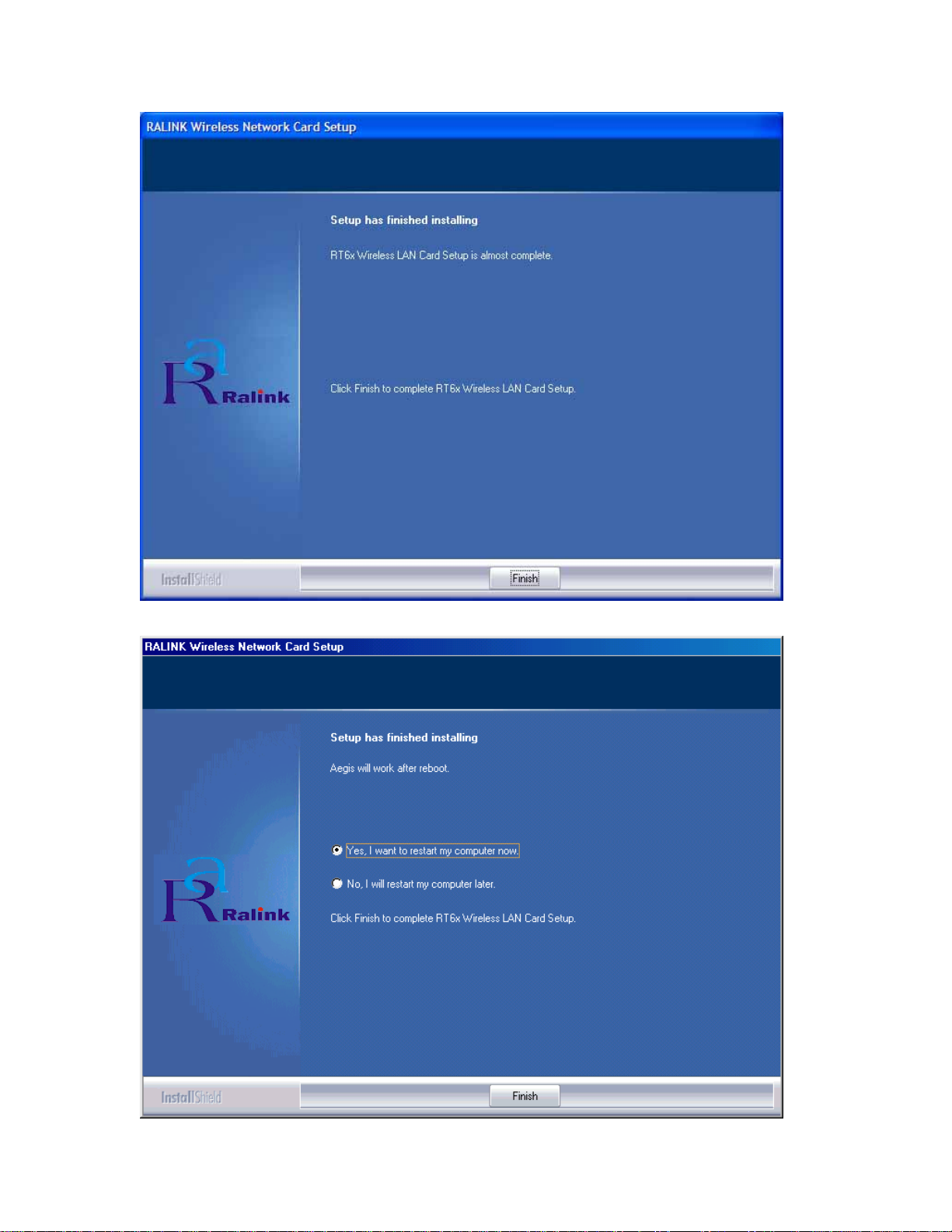
Fig 4-4
Fig 4-5

4.2 Insert the Wireless-G PCI Adapter
4.2.1 To insert the Wireless-G PCI Adapter into a desktop computer, please follow the steps
below:
Turn off your computer.
Open the case and locate an available PCI slot on the motherboard. Check with computer
manufacturer for instructions.
Slide the PCI Adapter into the PCI slot. Make sure that all its pins are touching the slot's
contacts. You may have to apply a bit of pressure to slide the adapter all the way in. After
the adapter is firmly in place, secure its fastening tab to your PC's chassis with a mounting
screw and close the case.
Attach the external antenna to the adapter’s antenna connector.
Power on your desktop PC.
4.2.2 Windows will automatically detect the adapter and complete the Wireless-G PCI Adapter
installation automatically.
(Note: In Windows ME and 98SE, following the hardware installation Windows will ask to
restart the computer, just click Yes to restart.)
5.UsingtheConfigurationUtilityfor
98SE/ME/2000/XP
5.1Overview
The wireless Configuration Utility can be used to check link information, search for available
wireless networks, or to create profiles that hold different configuration settings.
5.2 Access the Configuration Utility
The Configuration Utility icon will appear in your system tray. Double-click the icon. (Fig 5-1)
Fig 5-1
The utility is divided into six parts: Profile, Link Status, Site Survey, Statistics, Advance, and
About. You should change all your configuration settings for the Wireless-G PCI Adapter by
using this utility and not with the Network Properties section in the Control Panel.
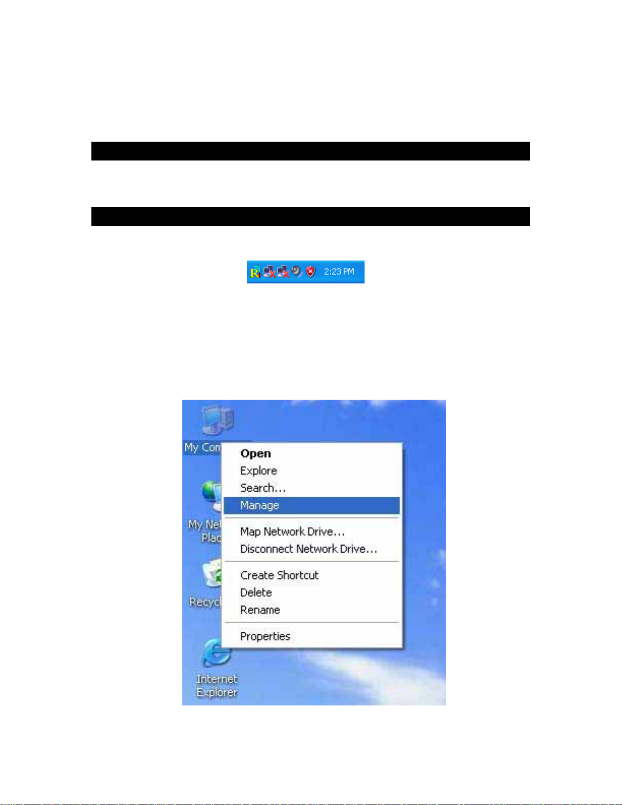
Note: In Windows XP, you should disable the Wireless Zero Configuration service following
the steps below:
A. Right Click My Computer on the desktop and select Manage. (Fig 5-2).
Fig 5-2
B. The Computer Management window comes up. Select Services from the Services and
Applications menu. Scroll down to locate Wireless Zero Configuration service.(Fig 5-3)

Fig 5-3
C. Double Click on Wireless Zero Configuration to go into its properties (Fig 5-4). For Startup
type, choose Disable to disable the Wireless Zero Configuration then click Apply and OK to
make the changes effective. Now you can use our Configuration Utility rather than Windows
XP Wireless Zero Configuration Utility.
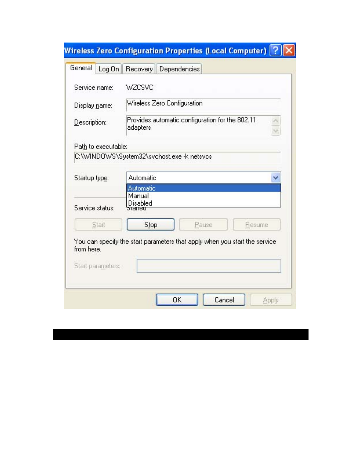
Fig 5-4
5.3Profile
The Profile screen (Fig 5-5) allows configuring and saving different configuration profiles for
different network setups.
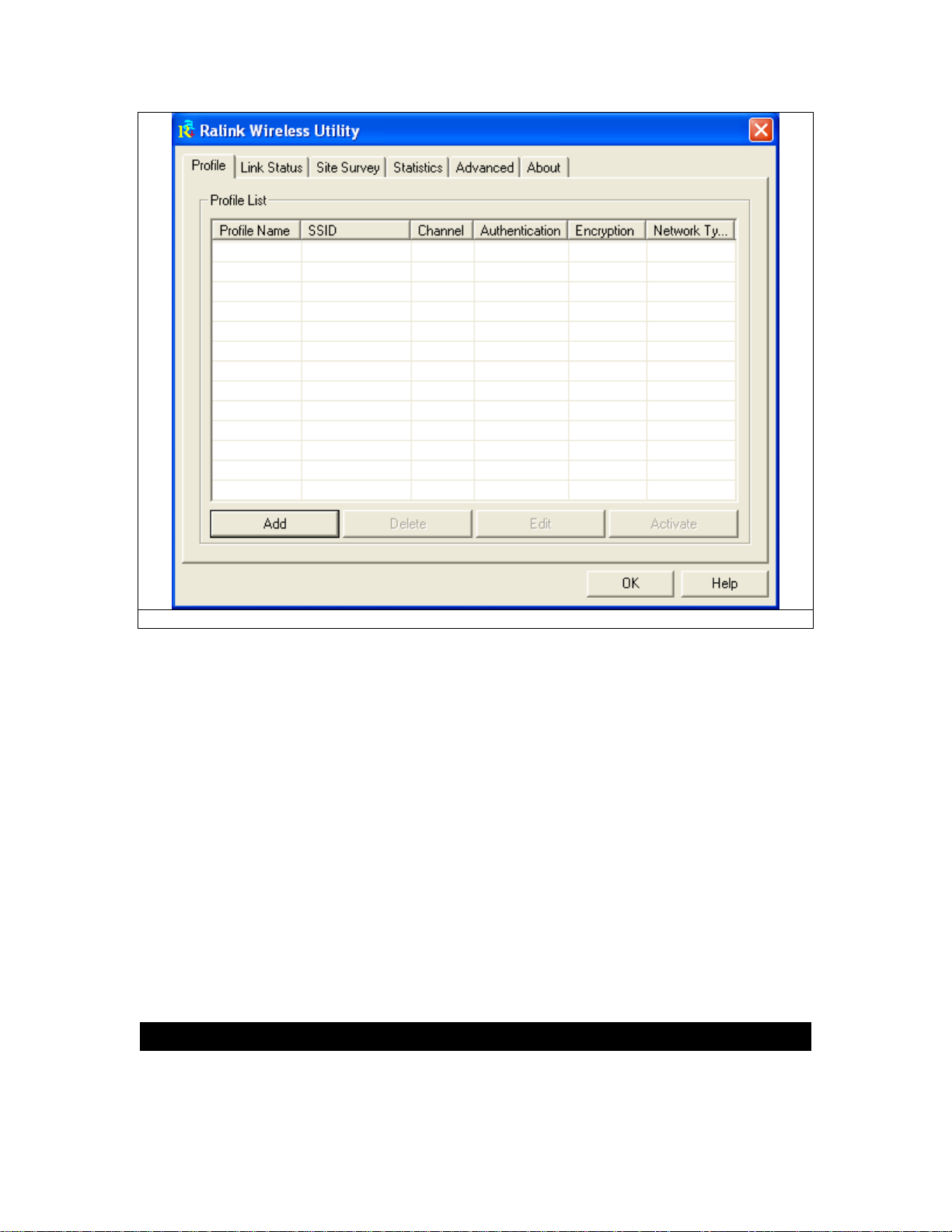
Fig 5-5
Profile Name – Connection profile name.
SSID – SSID used for this profile.
Channel – The channel which the wireless network devices are set on.
Authentication – The Authentication method used in this profile.
Encryption – The Encryption type used for this profile.
Network Type – The Network type used for this profile.
Add- Click Add to create a new profile. Please refer to “5.4 Create a New Profile”.
Delete - Click the Delete button to delete a selected profile.
Edit- Select a profile, and click the Edit button to change an existing profile.
Activate- To activate a specific profile, select the profile, and click the Activate button.
5.4CreateaNewProfile
Click the “Add” button on the Profile screen to create a new profile. (Fig. 5-6) shows the Add
Profile screen,
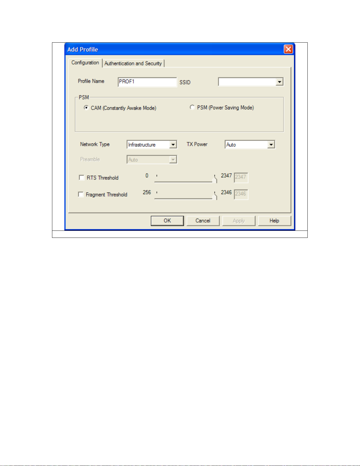
Fig 5-6
1- Enter the Profile Name.
2- Fill in the page with the following information.
SSID: Enter the SSID for the wireless network.
Network Type: There are two wireless modes.
(A) Infrastructure - This mode allows wireless and wired networks to communicate through an
access point.
(B) Ad-Hoc - This mode allows wireless-equipped computers to communicate directly with
each other.
3- Configure Authentication and Security
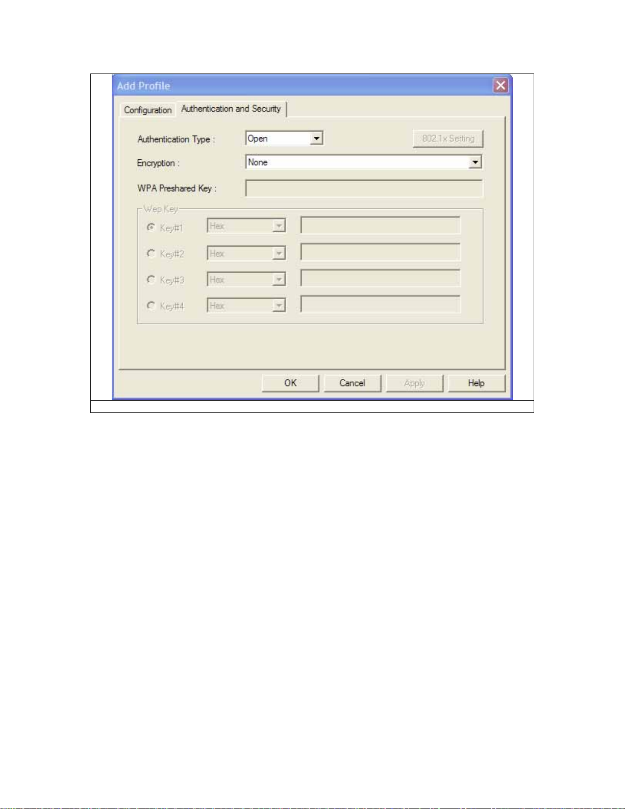
Fig 5-7
Authentication Type: There are seven type of authentication modes: Open, Shared, LEAP,
WPA, WPA-PSK, WPA2 and WPA2-PSK system.
A. LEAP
Light Extensible Authentication Protocol. It is an EAP authentication type used primarily
in Cisco Aironet WLANs. It encrypts data transmissions using dynamically generated WEP
keys, and supports mutual authentication.
1. Enter Identity
2. Enter Password
3. Click “OK” to save the profile.
B. Open System or Shared Key
1. Select Authentication type: Open System or Shared Key.
2.Select Encrytion: WEP
3.Select the key number that will be used
4.Enter the WEP key: There are several formats to enter the keys.
1. Hexadecimal、64bits:10 Hex characters.
2. Hexadecimal、128bits:32Hex characters.
3. ASCII、40bits:5 ASCII characters.
4. ASCII、128bits:13 ASCII characters.
4.Click “Use 802.1x”, if you want to use it. Refer to section “4- 802.1x Setting”.
5.Click “OK” to save the profile. Please see the Fig 5-8.

Fig 5-8
C. WPA, WPA-PSK, WPA2 or WPA2-PSK
1. Select Authentication type: WPA, WPA-PSK, WPA2 or WPA2-PSK
2. Select Encryption type: TKIP or AES. Please see Fig 5-9
3. Enter WPA Preshared Key, only valid for WPA-PSK and WPA2-PSK. This key should
be between 8 and 32 characters in length..
4.Click “OK” to save the profile. Please see Fig 5-9.

Fig 5-9
4- 802.1x Setting
A. Click “802.1x Setting” button. Please see the Fig 5-10

Fig 5-10
802.1x is an authentication mechanism for 『WPA』and 『WPA2』.
802.1x Authentication types:
1. PEAP: Protected Extensible Authentication Protocol. PEAP transports authentication
data by using tunneling between PEAP clients and an authentication server. PEAP can
authenticate wireless LAN clients using only server-side certificates, thus simplifying the
implementation and administration of a secure wireless LAN.
2. TLS∕Smart Card: Transport Layer Security, provides for certificate-based and mutual
authentication of the client and the network. It relies on client-side and server-side certificates to
perform authentication and can be used to dynamically generate user-based and session-based
WEP keys to secure subsequent communications between the WLAN client and the access point.
3. TTLS: Tunneled Transport Layer Security, this security method provides for
certificate-based, mutual authentication of the client and network through an encrypted channel.
Unlike EAP-TLS, EAP-TTLS requires only server-side certificates.
4. MD5-Challenge: Message Digest Challenge, is an EAP authentication type that
provides base-level EAP support. It only supports one-way authentication i.e. there is no mutual
authentication of wireless client and the network. It’s only valid for profile’s authentication type to
be none or shared.
B. If you want to use CA server, please click “CA Server” page. Depending on the EAP in
use, only the server or both the server and client may be authenticated and require a
certificate. Server certificates identify a server, usually an authentication or RADIUS server
to clients. Most EAPs require a certificate issued by a root authority or a trusted
commercial CA. Show as the Fig 5-11

Fig 5-11
1. Certificate issuer: Choose to use server that is the issuer of certificates.
2. Allow intermidiate certificates: It must be in the server certificate chain between the server
certificate and the server specified in the certificate issuer field.
3. Server name: Enter the authentication server’s name.
4.Please click “OK” to save the profile.
5.5LinkStatus
The Link Status (Fig 5-12) provides the link information of the Wireless-G PCI Adapter.
The Status displays current connection status. If no connection, it will show
Disconnected. Otherwise, the SSID and BSSID will show here.
The Extra Info displays link status and current channel in use.
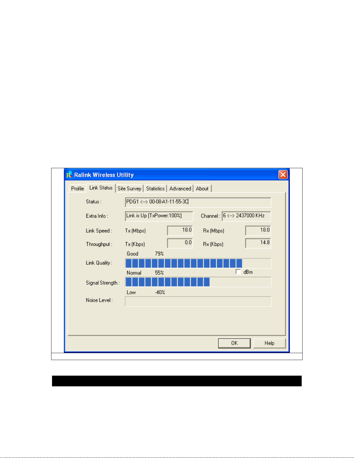
The Channel field shows the channel which the wireless network devices are currently using.
The Link Speed: Tx(Mbps) field shows the transfer rate in megabits per second.
Rx(Mbps) field shows the receive rate in megabits per second.
The Throughput (Kbps) field is the amount of data moved successfully form one place
to another in a given time period.
The Link Quality field will display a bar indicating percentage, between 0 and 100
percent.
The Signal Strength field will display a bar indicating percentage, between 0 and 100
percent.
The Noise Level displays noise signal strength.
Fig 5-12
5.6SiteSurvey
The site survey page displays a list of all Infrastructure and Ad-Hoc wireless networks available
for connection. (Fig 5-13)
Other manuals for CWP-854
3
Table of contents
Other CNET PCI Card manuals


Popular PCI Card manuals by other brands

SMC Networks
SMC Networks WPCI-GM - annexe 2 Quick installation guide

StarTech.com
StarTech.com PEXUSB3S7 instruction manual

Renkforce
Renkforce 2620931 operating instructions

Advantech
Advantech PCIE-1765 user manual

APM
APM IEEE 802.11g High power PCI Adapter... Specifications

Artesyn
Artesyn SharpMedia PCIE-8120 quick start guide


