CoaxPress ELIIXA+ 16k CXP Color User manual
ELIIXA+ 16k/8k CXP Color
Cmos Multi-Line Color Camera
User Manual

ELIIXA+®
16k/8k CXP Color
2e2v semiconductors SAS 2013
Summary
1
CAMERA OVERVIEW............................................................................. 5
1.1 Features.................................................................................................................................................... 5
1.2 Key Specifications.................................................................................................................................. 5
1.3 Description............................................................................................................................................... 6
1.4 Typical Applications ............................................................................................................................... 6
2
CAMERA PERFORMANCES.......................................................................7
2.1 Camera Characterization ...................................................................................................................... 7
2.2 Image Sensor........................................................................................................................................... 8
2.2.1 True Colour Mode (TC)......................................................................................................................................................8
2.2.2 Full Definition Single Mode (FD Single)........................................................................................................................9
2.2.3 Full Definition Enhanced Mode (FD Enhanced) ...........................................................................................................9
2.3 Response & QE curves ............................................................................................................................. 10
2.3.1 Quantum Efficiency......................................................................................................................................................... 10
2.3.2 Spectral Response............................................................................................................................................................ 10
3
CAMERA HARDWARE INTERFACE ........................................................... 11
3.1 Mechanical Drawings............................................................................................................................ 11
3.2 Input/output Connectors and LED ................................................................................................... 12
3.2.1 Power Over CoaXPress.................................................................................................................................................... 13
3.2.2 Status LED Behaviour ..................................................................................................................................................... 13
3.2.3 Trigger Connector............................................................................................................................................................ 14
4
STANDARD CONFORMITY.................................................................... 15
4.1 CE Conformity........................................................................................................................................ 15
4.2 FCC Conformity ..................................................................................................................................... 15
4.3 RoHs Conformity................................................................................................................................... 15
5
GETTING STARTED ........................................................................... 17
5.1 Out of the box ...................................................................................................................................... 17
5.2 Setting up in the system..................................................................................................................... 17
6
CAMERA SOFTWARE INTERFACE ........................................................... 18
6.1 Control and Interface ......................................................................................................................... 18
6.2 Camera Commands................................................................................................................................... 19
6.2.1 Device Control................................................................................................................................................................... 19
6.2.2 Image Format.................................................................................................................................................................... 21
6.2.2.1 Structure of the Sensor.................................................................................................................................. 21
6.2.2.2 Forward/Reverse .............................................................................................................................................. 22
6.2.2.3 Test Image Pattern Selector......................................................................................................................... 23
6.2.3 Acquisition Control.......................................................................................................................................................... 24
6.2.3.1 External Triggers on GPIO Connector......................................................................................................... 25

ELIIXA+®
16k/8k CXP Color
3e2v semiconductors SAS 2013
6.2.3.2 CXP Trigger ........................................................................................................................................................ 25
6.2.3.3 Trigger Presets ................................................................................................................................................. 27
6.2.3.4 Rescaler............................................................................................................................................................... 28
6.2.4 Digital I/O Control ......................................................................................................................................................... 30
6.2.5 Counters and Timers Control......................................................................................................................................... 31
6.2.5.1 Counters .............................................................................................................................................................. 33
6.2.5.2 Timers.................................................................................................................................................................. 33
6.2.6 Gain and Offset............................................................................................................................................................... 34
6.2.6.1 White Balance.................................................................................................................................................... 35
6.2.7 Flat Field Correction ...................................................................................................................................................... 36
6.2.7.1 Automatic Calibration ...................................................................................................................................... 38
6.2.7.2 Manual Flat Field Correction .......................................................................................................................... 38
6.2.7.3 Save & Restore FFC.......................................................................................................................................... 38
6.2.8 Statistics and Line Profile ............................................................................................................................................ 39
6.2.9 Privilege Level .................................................................................................................................................................. 40
6.2.10 Save & Restore Settings ........................................................................................................................................... 41
7
APPENDIX A: Test Patterns .................................................................. 42
7.1 Fixed Horizontal Ramps ...................................................................................................................... 42
7.2 Color RGBW Fixed Pattern................................................................................................................. 43
7.3 Vertical wave ......................................................................................................................................... 43
8
APPENDIX B: Timing Diagrams ............................................................... 44
8.1 Synchronization Modes with Variable Exposure Time................................................................. 44
8.2 Synchronisation Modes with Maximum Exposure Time............................................................... 45
8.3 Timing Values ......................................................................................................................................... 45
9
APPENDIX C: Data Cables .................................................................... 47
10
APPENDIX D: Lenses Compatibility ........................................................ 48
11
Frame Grabbers Compliance ................................................................ 50
12
APPENDIX E: COMMANDS SUMMARY.................................................... 51
12.1 Category “Device Control” .................................................................................................................. 51
12.2 Image Format ........................................................................................................................................ 51
12.3 Synchro and Acquisition modes......................................................................................................... 52
12.4 Scan Direction....................................................................................................................................... 53
12.5 GenICam Trigger .................................................................................................................................. 53
12.6 Digital IO Control................................................................................................................................. 54
12.7 Counters.................................................................................................................................................. 55
12.8 Timers...................................................................................................................................................... 57
12.9 Rescaler................................................................................................................................................... 58
12.10 Gain & Offset .................................................................................................................................... 58
12.11 Flat Field Correction........................................................................................................................ 59
12.12 Save and restore User Configurations........................................................................................ 60

ELIIXA+®
16k/8k CXP Color
4e2v semiconductors SAS 2013
12.13 Camera Status................................................................................................................................... 60
12.14 Line Profile Average......................................................................................................................... 61
13
APPENDIX F: Revision History ............................................................. 62

ELIIXA+®
16k/8k CXP Color
5e2v semiconductors SAS 2013
1CAMERA OVERVIEW
1.1
Features
Cmos Colour Sensor :
o16384 RGB Pixels, 5 x 5µm (Full Definition)
o8192 RGB Pixels 10x10µm (True Colour)
Interface : CoaXPress® (4x 6Gb/sLinks)
Line Rate :
oUp to 47500 l/s In 16k Full Definition Mode
oUp to 95000 l/s in 8k True Colour Mode
Bit Depth : 24bits (RGB 8bits)
Scan Direction
Flat Field Correction
Low Power Consumption : <19W
Compliant with Standard Lenses of the Market
1.2
Key Specifications
Note : All values in LSB is given in 8 bits format
Characteristics
Typical Value
Unit
Sensor Characteristics at Maximum Pixel Rate
Resolution
16384 or 8192
RGB Pixels
pixel size (square)
5 or 10
µm
Max line rate
8192 RGB Pixels True Color Mode
95
kHz
16384 RGB Pixels Full Definition Modes
47.5
kHz
Radiometric Performance at Maximum Pixel Rate and minimum camera gain
Bit depth
3 x 8
Bits
Response (Peak) : True Color or Full Def. Enhanced
Red
11.8
LSB 8bits/(nJ/cm²)
Green
11.2
LSB 8bits/(nJ/cm²)
Blue
7.8
LSB 8bits/(nJ/cm²)
Response non linearity
< 1
%
PRNU HF Max
3
%
Dynamic range
65
dB

ELIIXA+®
16k/8k CXP Color
6e2v semiconductors SAS 2013
1.3
Description
e2v’s next generation of line scan cameras are setting new, high standards for line rate and image quality.
Thanks to e2v’s recently developed multi-line CMOS technology, the camera provides an unmatched 95,000
lines/s and combines high response with an extremely low noise level; this delivers high signal to noise ratio
even when short integration times are required or when illumination is limited. The 5μm pixel size is arranged in
four active lines and dual line filter configuration allowing the camera to be operated in several modes: True
colour mode with 10μm RGB pixels to provide equivalent colour fidelity to 10μm pixel tri-linear solutions with
advanced immunity to web variation or Full definition mode with a unique16,384 RGB pixel resolution.
1.4
Typical Applications
Printing Inspection
High Resolution Document Scanning
Printed Circuit Board Inspection
Flat Panel Display Inspection
High Quality Raw material Surface Inspection
Functionality (Programmable via GenICam Control Interface)
Analog Gain
Up to 12 (x4)
dB
Offset
-4096 to +4096
LSB
Trigger Mode
Timed (Free run) and triggered (Ext Trig, Ext ITC) modes
SensorModes
True Color : 8192 RGB Pixels of 10x10µm
Full Definition Enhanced : 16384 RGB Pixels 5x5µm
Full Definition Single : 16384 RGB Pixels 5x5µm
Mechanical and Electrical Interface
Size (w x h x l)
100 x 156 x 36
mm
Weight
700
g
Lens Mount
M95 x 1
-
Sensor alignment ( see chapter 4 )
±100
µm
Sensor flatness
±35
µm
Power supply
Power Over CoaXPress : 24
V
Power dissipation –Typ. while grabbing
< 19
W
General Features
Operating temperature
0 to 55 (front face) or 70 (Internal)
°C
Storage temperature
-40 to 70
°C
Regulatory
CE, FCC and RoHS compliant
ELIIXA+®
16k/8k CXP Color
7e2v semiconductors SAS 2013
2CAMERA PERFORMANCES
2.1
Camera Characterization
Unit
True Color (8k)
Full Definition
Single
Full Definition
Enhanced
Typ.
Max
Typ.
Max
Typ.
Max
Dark Noise RMS
LSB
0.12
1.2
0.11
1.2
0.12
1.2
Dynamic Range
-
2125:1
-
2125:1
-
2125:1
-
RMS Noise (3/4 Sat)
LSB
2.2
-
2.15
4
2.2
4
Full Well Capacity
e-
(per color)
13650
-
13650
-
13650
-
SNR (3/4 Sat)
dB
40
-
40
-
40
-
Peak Response
(460/530/660nm)
LSB 8bits/
(nJ/cm2)
8/10/12
-
4/5/6
-
8/10/12
-
Non Linearity
%
0,3
-
0,3
-
0,3
-
Without Flat Field Correction :
FPN rms
LSB
0.21
1
0.23
1
0.22
1
FPN pk-pk
LSB
1
2
1
2
1
2
PRNU hf (3/4 Sat)
%
0.13
0,35
0.123
0,35
0.14
0,35
PRNU pk-pk (3/4 Sat)
%
1.1
3
1
3
1.25
3
Test conditions :
All values are given at Nominal Gain (0dB) : Preamp Gain x1, Amp Gain 0dB
Figures in LSB are for a 8bits format
Measured at exposure time = 400µs and line period = 400µs in Ext Trig Mode (Max Exposure Time)
Maximum data rate
ELIIXA+®
16k/8k CXP Color
8e2v semiconductors SAS 2013
2.2
Image Sensor
The Eliixa+ Colour 16k sensor is composed
of two pairs of sensitive lines.
The Colour version has been completed
with RGB colour Filter and disposed as
detailed beside.
Each pair of lines use the same Analog to
Digital Column converter (ADC Column). An
appropriate (embedded) Time delay in the
exposure between each line this allows to
combine two successive exposures in order
to double the sensitivity of a single line.
This Time Delay Exposure is used only in
the Full Definition Enhanced mode (See
Below).
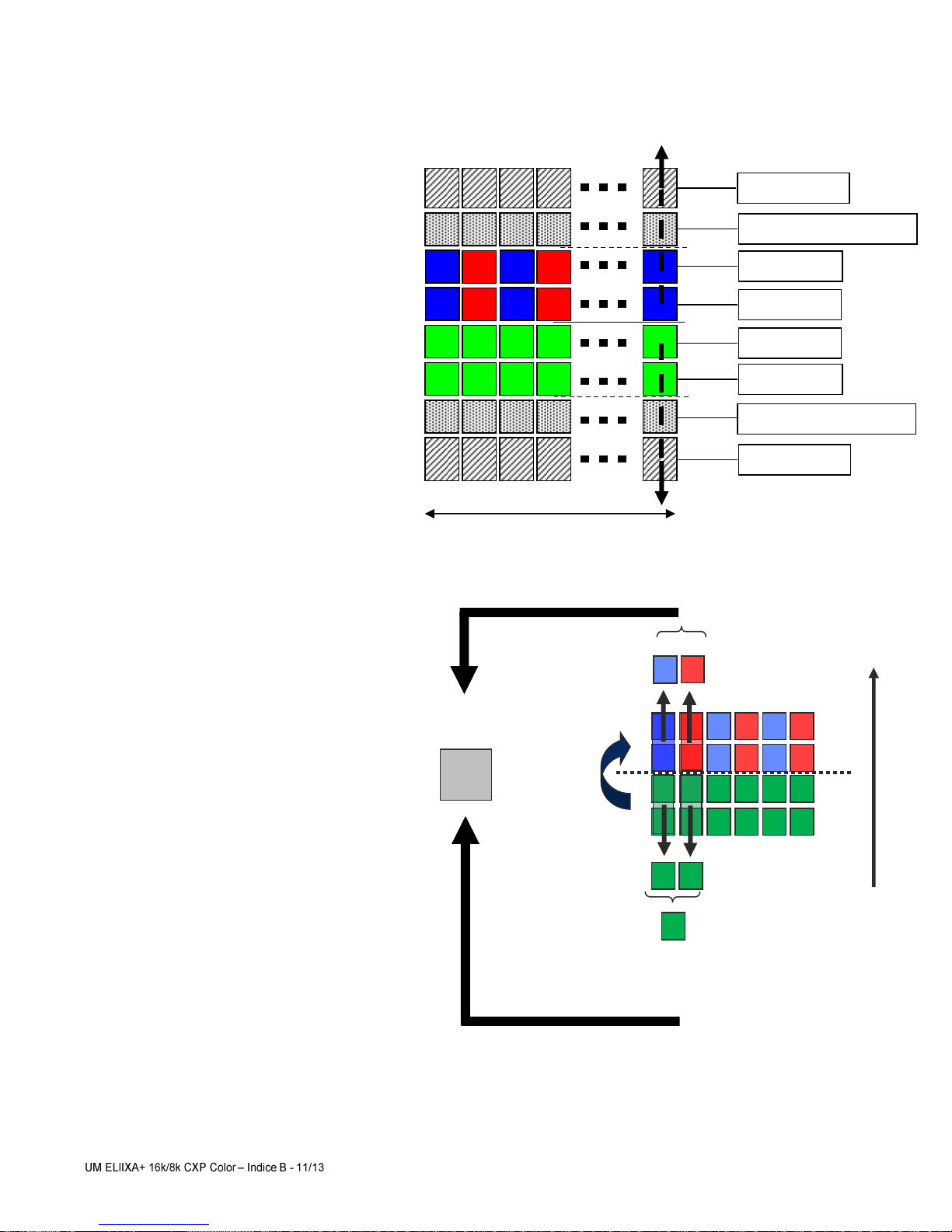
2.2.1 True Colour Mode (TC)
10µm pixels (R,G,B)
Twice less pixels than B/W
Requires x3/2 the data flow of B&W
Only one (High Sensitivity) TC mode
available : Equivalent to 6 x Pixels of
5µm (with their respective colour
filters).
“Full Exposure control” not needed in
TC as the TDI is not active (only
binning). The Exposure time can be
control as for a single line mode.
Delay : 1 line
of 10µm
Double Green :
Vertical Binning
Double Red :
Vertical Binning
Double Blue :
Vertical Binning
Pixel 10µm
{RGB}
Double Green :
Vertical Binning
Green Pixels
averaging
Web
Direction
8192 Pixels
ADC Column
ADC Column
Intermediate Blind Pixel
Pixel Line A
Pixel Line B
Pixel Line C
Pixel Line D
Intermediate Blind Pixel

ELIIXA+®
16k/8k CXP Color
9e2v semiconductors SAS 2013
2.2.2 Full Definition Single Mode (FD Single)
5µm pixels (R,G,B)
Same definition than B&W
Requires x3 the data flow of the B&W
Sensitivity is half of the TC mode
available : Equivalent to 3 x Pixels of
5µm (with their respective colour
filters).
“Full Exposure control” not needed in
this mode as the Time Delay
Exposure is not active. The Exposure
time can be control as for a single line
mode.
2.2.3 Full Definition Enhanced Mode (FD Enhanced)
5µm pixels (R,G,B)
Same definition than B&W
Requires x3 the data flow of the B&W
Sensitivity is the same as the TC
mode available : Equivalent to 6 x
Pixels of 5µm (with their respective
colour filters).
“Full Exposure control” is activated in
this mode as the Time Delay
Exposure is active.
Delay : 1 line
of 5µm
Single Green
Single Red
Single Blue
Blue or Red
Interpolated(*)
Pixel 5µm
{RGB}
Single Green
Web
Direction
Delay : 1 line
of 5µm
Double Green
TDE
Double Green
TDE
Double Red
TDE
Double Blue
TDE
Blue or Red
Interpolated(*)
Pixel 5µm
{RGB}
Web
Direction

ELIIXA+®
16k/8k CXP Color
10 e2v semiconductors SAS 2013
2.3 Response & QE curves
2.3.1 Quantum Efficiency
2.3.2 Spectral Response
Spectral response (Chip 1240-005 - f/3.5 - With glass)
0
1
2
3
4
5
6
7
8
9
350 400 450 500 550 600 650 700 750 800 850 900 950 100
0105
0110
0
Wavelength (nm)
Spectral Response (LSB 8-bit/(nJ/cm²))
Blue
Green blue
Green red
Red
B&W

ELIIXA+®
16k/8k CXP Color
11 e2v semiconductors SAS 2013
3CAMERA HARDWARE INTERFACE
3.1
Mechanical Drawings
Z
X
Y
The Step file is available
on the web :
www.e2v.com/cameras

ELIIXA+®
16k/8k CXP Color
12 e2v semiconductors SAS 2013
3.2
Input/output Connectors and LED
Sensor alignment
Z = -9.4 mm
±100µm
X = 9 mm
±100 µm
Y = 50mm
±100 µm
Flatness
±25 µm
Rotation (X,Y plan)
±0,1°
Tilt (versus lens mounting plane)
50µm
USB Connector
For Firmware
upgrade
Trigger Connector
Multi-Colored
LED for Status
and diagnostic
CoaXPress
Connectors

ELIIXA+®
16k/8k CXP Color
13 e2v semiconductors SAS 2013
3.2.1 Power Over CoaXPress
The ELIIXA+ CXP is compliant with the Power Over CoaXPress : There is no Power connector as the power
is delivered through the Coaxial Connectors 1 and 2.
In the Standard, the Power Over CoaXPress allows to deliver 13W (under 24V) per Channel.
The ELIIXA+ CXP requires 19W then two connectors are required for the power : The two first are used
for this purpose.
If you want to Power ON the Camera you have to connect the Coaxial connector output 1 of the
camera to the coaxial connector 1 of the Frame Grabber.
Note 1 :
Only the connector 1 position is mandatory. They other 3 connectors can be inverted but the
camera still needs the 2 first connectors to get it power and be able to start up.
Note 2 :
Removing the 2 first connectors will shut down the Camera : You can reset the Camera by quickly
(
less than 1s
) connect/disconnect the Connector CXP1 but after a longer shut down, you’ll have to reboot
the PC with the Camera full connected to the frame grabber in order to synchronize the discovery of each
power line.
Note 3
: With some frame grabber you have access to a specific command (from the Frame Grabber
interface) for shutting down/up the power of the CoaxPress : This solution, with the complete reboot, is
the better solution to ensure a complete power On of the Camera.
3.2.2 Status LED Behaviour
The Power LED behavior detail is the following :
Colour and State
Meaning
Off
No power
Solid orange
System booting
Fast flash green Shown for a minimum of 1s even if the
link detection is faster
Link detection in progress
Slow flash alternate red / green
Device / Host incompatible
Slow pulse green
Device / Host connected, but no data being transferred
Slow pulse orange
Device / Host connected, waiting for event (e.g. trigger,
exposure pulse)
Solid green whenever data transferred (i.e. blinks
synchronously with data)
Device / Host connected, data being transferred
500ms red pulse In case of multiple errors, there shall
be at least 200ms green before the next error is
indicated
Error during data transfer (e.g. CRC error, single bit
error detected)
Fast flash red
System error (e.g. internal error)

ELIIXA+®
16k/8k CXP Color
14 e2v semiconductors SAS 2013
3.2.3 Trigger Connector
Camera connector type: Hirose HR10A-7R-5SB or compliant
Cable connector type: Hirose HR10A-7P-5P (male) or compliant, Provided with the Camera
IN1/IN2 are connected respectively to Line0/Line1 and allow to get external line triggers or the
forward/Reverse “Live” indication.
On the Connector side, the 120Ω termination is validated only if the input is switched in LVDS or
RS422. The electrical schematic is detailed below :
Signal
Pi
n
LVDS IN1+ / TTL IN1
1
LVDS IN1-
2
LVDS IN2+ / TTL IN2
3
LVDS IN2-
4
GND
5
1
2
3
5
5
4
Receptacle viewed from camera back

ELIIXA+®
16k/8k CXP Color
15 e2v semiconductors SAS 2013
4STANDARD CONFORMITY
The ELIIXA+ cameras have been tested using the following equipment:
A shielded Trigger cable
A 10m CoaXPress Cable for the data transfer, certified at 6Gb/s
e2v recommends using the same configuration to ensure the compliance with the following standards.
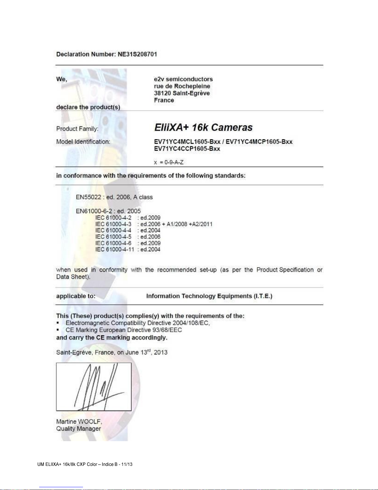
4.1
CE Conformity
The ELIIXA+ cameras comply with the requirements of the EMC (European) directive
2004/108/CE (EN50081-2, EN 61000-6-2) (see next page).
4.2
FCC Conformity
The ELIIXA+ cameras further comply with Part 15 of the FCC rules, which states that: Operation is
subject to the following two conditions:
This device may not cause harmful interference, and
This device must accept any interference received, including interference that may cause
undesired operation
This equipment has been tested and found to comply with the limits for Class A digital device, pursuant to
part 15 of the FCC rules. These limits are designed to provide reasonable protection against harmful
interference when the equipment is operated in a commercial environment. This equipment generates, uses
and can radiate radio frequency energy and, if not installed and used in accordance with the
instruction manual, may cause harmful interference to radio communications. Operation of this equipment in
a residential area is likely to cause harmful interference in which case the user will be required to correct
the interference at his own expense.
Warning: Changes or modifications to this unit not expressly approved by the party responsible for
compliance could void the user's authority to operate this equipment.
4.3
RoHs Conformity
ELIIXA+ cameras comply with the requirements of the RoHS directive 2011/65/EU.
ELIIXA+®
16k/8k CXP Color
16 e2v semiconductors SAS 2013

ELIIXA+®
16k/8k CXP Color
17 e2v semiconductors SAS 2013
5GETTING STARTED
5.1
Out of the box
The contains of the Camera box is the following :
-One Camera ELIIXA+
-Trigger connector (
Hirose HR10A-7P-5P-male or compliant)
5.2
Setting up in the system
The Compliant Lenses and their accessories are detailed in Appendix E
There is no CDROM delivered with the Camera : This User Manual , and any other corresponding
documents can be dowlaoded on the Web site.
Main Camera page : www.e2v.com/cameras
Select the appropriate Camera Page (ELIIXA+)
FOV
Focal Plan
Sensor Plan
f
L
w
s
w
f
FOV
L
=
ELIIXA+®
16k/8k CXP Color
18 e2v semiconductors SAS 2013
6CAMERA SOFTWARE INTERFACE
6.1
Control and Interface
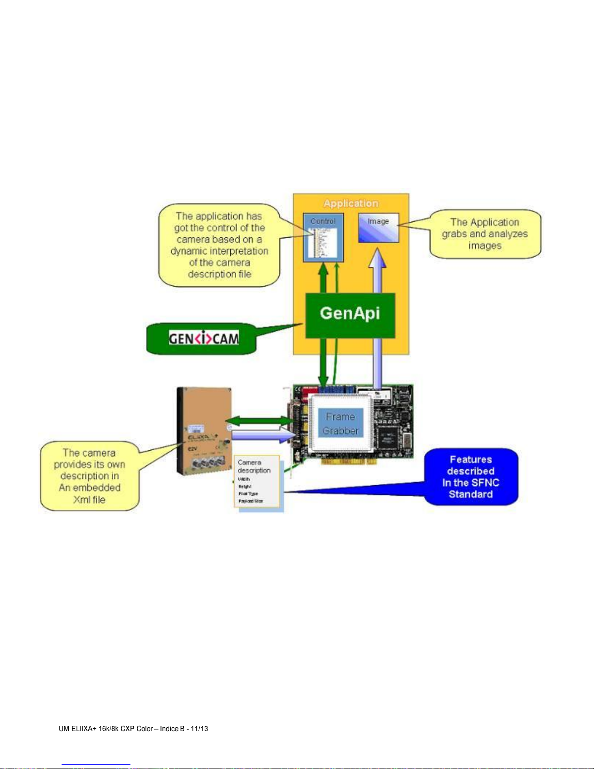
The ELIIXA+ CoaxPress Camera is compliant with GenICam 2.1 and the SFNC 1.5 standards.
This means that the Camera embeds its own definition and parameter description in an xml file.
Most of these Parameters are compliant with the SNFC. The specific parameters (non SNFC) are still
compliant with GenICam and can be detailed through the GenICam API process to the application.
The Frame Grabber software is supposed to propose a feature Brother, based on GenICam, which lists and
allows the modification of the parameters of the Camera.
This feature brother based on GenICam API uploads the xml file of the parameters description embedded in
the Camera.
Then the following description of the parameters and commands is based on the GenICam name of these
parameters. Behind each parameter is a register address in the Camera memory.
The mapping of these registers is not given in this manual because it can change from one version or the
firmware to the next one.

ELIIXA+®
16k/8k CXP Color
19 e2v semiconductors SAS 2013
6.2 Camera Commands
6.2.1 Device Control
These are Identification values of the Camera. They can be accessed in the “Device Control” section
Feature
Description
DeviceVendorName
Get camera vendor name as a string (including ‘\0’)
DeviceModelName
Get camera model name as a string (including ‘\0’)
DeviceFirmwareVersion
Get camera synthetic firmware version (PKG version)
as a string (including ‘\0’)
DeviceVersion
Get camera version as a string (hardware version)
(including ‘\0’)
DeviceManufacturerInfo
Get camera ID as a string (including ‘\0’)
DeviceUserID
Get device user identifier as a string (including '\0')
DeviceID
Read Serial Nb
ElectronicBoardID
Read Electronic Board ID
DeviceSFNCVersionMajor
1
DeviceSFNCVersionMinor
5
DeviceSFNCVersionSubMinor
0
DeviceTemperatureSelector
Device Temperature selector
DeviceTemperature
Read Main board internal temperature (format signed Q10.2 = signed 8 bits, + 2 bits
below comma. Value from -512 to +511) in °C
DeviceScanType
Linescan
Standby
Disable : Standby mode (“False”)
Enable : Standby mode (“True”), no more video available but save power and
temperature
Status Register
StatusWaitForTrigger
Bit 0: true if camera waits for a trigger during more than 1s
Status trigger too fast
Bit 1: true if camera trigger is too fast
Reserved for Factory
Bit 2 to 7
StatusWarningOverflow
Bit 8: true if a an overflow occurs during FFC calibration or Tap balance (available
only for integrator/user mode)
StatusWarningUnderflow
Bit 9: true if a an underflow occurs during FFC calibration or Tap balance (available
only for integrator/user mode)
Reserved for Factory
Bit 10
Scrolling direction
Bit 11: 0 : forward, 1: reverse
StatusErrorHardware
Bit 16 : true if hardware error detected
ELIIXA+®
16k/8k CXP Color
20 e2v semiconductors SAS 2013
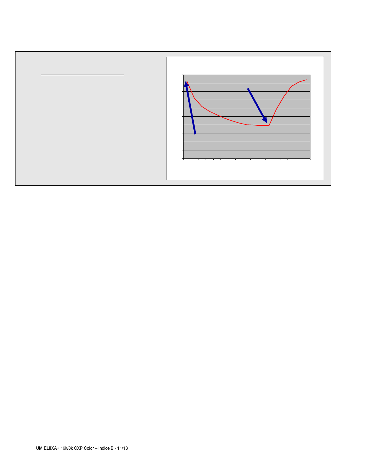
A standby mode, what for ?
The Standby mode stops all activity on the
sensor level. The power dissipation drops
down to about 6W. During the standby
mode, the grab is stopped
Once the Standby mode turned off, the
Camera recovers in less than 1ms to send
images again from the sensor.
Internal Temperature
25
30
35
40
45
50
55
60
65
70
75
0
5
7
10
20
30
40
50
60
70
80
90
100
110
120
130
140
Time (mn)
°C
Standby Off
Standby On
This manual suits for next models
1
Table of contents


