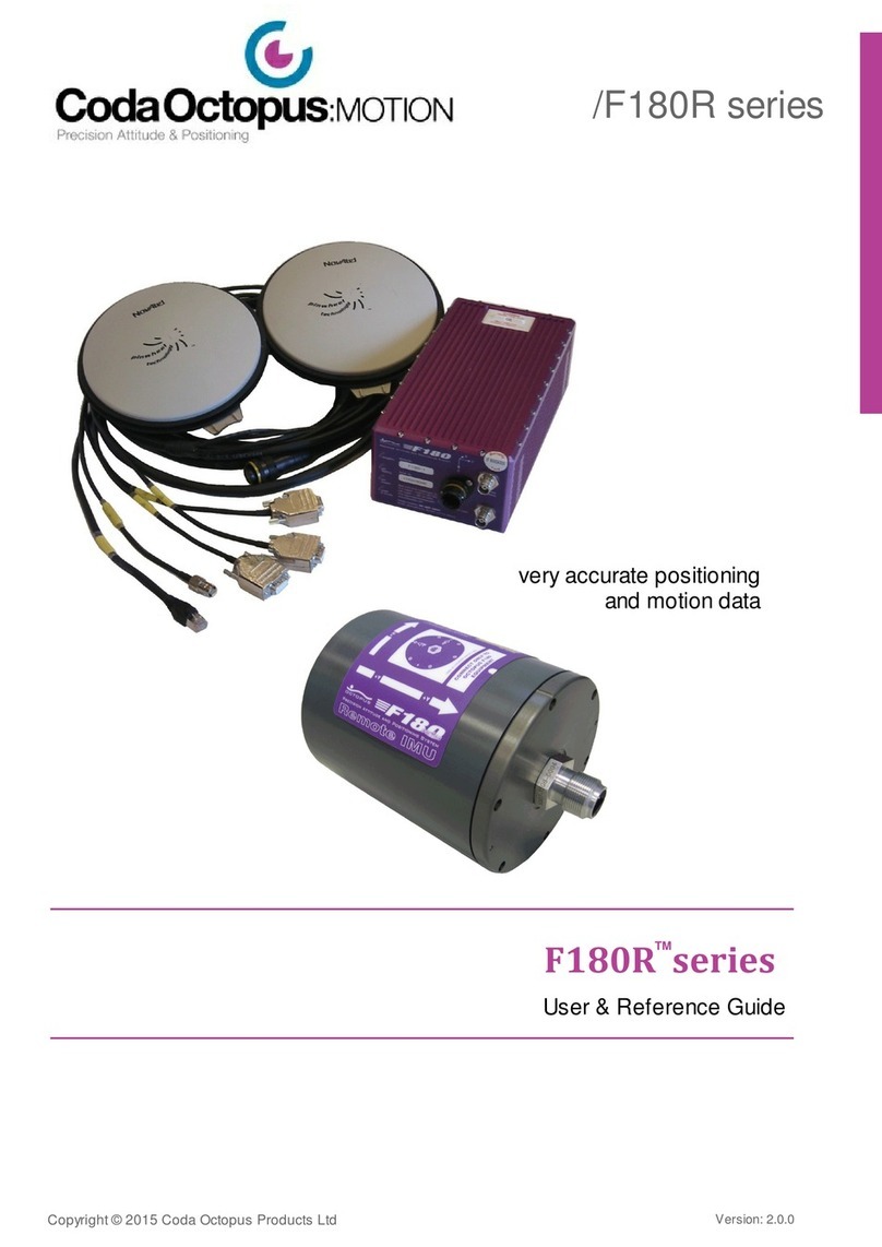
CodaOctopus F180 User manual

F180 Quick Start Guide
Admiral House
29/30 Maritime Street
Leith
Edinburgh
EH6 6SE
Tel: 44 (0)131 553 1380
Fax: +44 (0)131 554 7143
Suite III
Business Centre
Castle Farm
Deddington
Oxfordshire OX15 0TP
Tel: +44 (0)1869 337570
Fax: +44 (0)1869 337571
CodaOctopus Ltd
Email: [email protected]
24 hr Technical Support:
Worldwide : +44 (0)131 553 7003
North America : +1 888 340 CODA

© 2004 CodaOctopus Ltd
1F180 Quick Start Guide
This guide provides a summary of the main tasks and procedures required to install,
configure, calibrate and operate an Octopus F180 unit. To deploy the unit you will
require:
·
F180 unit and associated components ( supplied in self-contained case )
·
F180 application software ( supplied with unit in self-contained case )
·
Antenna mounting bar ( user supplied )
·
PC running
Microsoft® Windows ™ 2000 or XP operating system ( user supplied )
Using this procedure you should be able to quickly setup your F180 and obtain high
quality measurements.
Version 6.0 - 16/12/04

© 2004 CodaOctopus Ltd
1.1 Block Diagram

© 2004 CodaOctopus Ltd
1.2 Installation & Measurement
Installing the F180 is relatively simple; however care should be taken to ensure that the F180 antenna
are appropriately located AND that their relative locations are accurately known. The critical issues to
which attention must be paid are:
1.
IMU Orientation
2.
Antenna Baseline
3.
Antenna Position
1.2.1IMU Mounting
The IMU (purple box) should be located as near as possible to
the sensor whose motion it is to measure,
e.g.
echosounder/multibeam transducer. If the transducer experiences
vibration or motion significantly different to that experienced on the
vessel, it is advisable to mount the IMU on the same mounting as the
transducer.
The F180 DOES NOT need to be mounted at the vessel centre of
gravity (CoG) and its performance will not be degraded in any way by
not mounting it at the vessel CoG. The F180 software also allows the
user to mount the F180 at a practical location and specify at which
point on the vessel you wish the motion to be measured using the
'remote lever arm' option found under
Step 7 of the Configuration
Wizard.
N.B. It is important to note that lever arm offsets should only be applied once, either in
the F180 software or in your multibeam software. Do not apply them twice.
Wherever practical, always mount the F180 flat and square relative
to the vessel, and aligned to the vessel's heading
as closely as
possible as shown. This may be achieved by using part of the vessel's
structure as a point of reference.
If it is not possible to accurately position the F180 IMU against a known
reference,
Step 6 of the Configuration Wizard
allows you to set Vessel
Orientation Offsets so that the outputs are relative to the transducer being
measured, rather than the box itself.
The F180 is splash proof and should be kept away from or shielded from
direct exposure to water.

© 2004 CodaOctopus Ltd
1.2.2Antenna Mounting
Antennas should be mounted where they have a clear, unobstructed view of the
sky at all times.
There are two CRITICAL issues relating to antenna mounting to which
close attention should be paid:
Antenna Baseline
Antenna baseline (separation between antennas) must be accurately measured
to within 5mm or better. To achieve this, it is recommended that a pre-fabricated bar
with accurate mounting points is used. The user can select baseline lengths anywhere
between 1m – 4m however the general recommendation is to use a baseline of
2.0m or
less
.
Tech Tip
Optimal system performance during the heading initialisation and calibration
phases can be achieved by using the smallest antenna baseline that delivers
measurements meeting the users specification. Thus optimal heading
initialisation periods and calibration times are achievable with baseline lengths
of
2.0m
or less.
Care should also be taken to ensure that both antennas are mounted similarly, i.e. with
the connector pointing in approximately the same direction.
Antenna Position
Antenna position relative to the IMU is required when configuring the F180. Accurate
knowledge of antenna position relative to the IMU will speed up calibration, helping to
ensure accuracy.
The position of the
PRIMARY
antenna (topmost antenna connector) needs to be
measured as accurately as possible, ideally to within 0.5m or better, however a close
approximation to within 1m is preferable to no measurement.
The three GPS offsets X, Y and Z as shown should be noted ready for use during the
configuration phase where they will be entered in
Step 4 of the Configuration Wizard.
Note: Take care to observe the correct
sign/polarity of each offset measured.
The position of the secondary antenna relative to
the primary antenna and IMU, must be known,
ideally to within 5 degrees.
The typical configuration is for the antenna bar to
be oriented port-starboard with the primary
antenna on the port and the IMU located with the
connectors pointing aft.
These values for
GPS Antenna Baseline
Orientation
are input in
Step 5 of the
Configuration Wizard.

© 2004 CodaOctopus Ltd
Tech Tip
Antenna location is important to ensure no degradation of received signal
quality. The antenna are sensitive to electromagnetic radiation from other
devices in the immediate environment such as UHF transmitters. Installation
criteria:
·
In an elevated position with a clear view of the sky
·
Rigidly with respect to each other and IMU
·
In a low multi-path environment
·
More than 5 metres away from UHF/satellite communication or other
communication devices

© 2004 CodaOctopus Ltd
1.3 Connection
All connections for communications and power are via
a single multi way cable with the following
connectors:
·
Power (9-18Vdc)
·
Serial communications (RS232) X 3
·
Ethernet RJ45 (100baseT)
·
1PPS
·
Attitude and position information is output on standard 9 way D-type connectors
serial 1 and serial 2 in configurable industry standard message formats.
See Step 9
& 10 of the Configuration Wizard
.
·
DGPS and RTK correction messages may be sent on the GPS correction serial
connector. The F180 application software allows you to configure the system for the
correction input type and rate you will use.
See Step 3 of the Configuration
Wizard.
·
Ethernet is used to control/configure the F180 and to receive high data rate position,
attitude, processed heave (iHeave) and extensive diagnostic data from the F180 in
Octopus MCOM format.
See Step 2 of the Setup Wizard.
·
The F180 is set as standard with an IP address of 195.0.0.180. If your PC is not set
to a similar network IP address you will only be able to receive data from the F180.
To configure and control the F180 via the network interface the two systems, host PC
and F180, need to be on the same IP Address range.
Once connected and the F180 has been turned on the user should allow 15 minutes
from a cold start up for the sensors within the F180 to reach operating temperature.

© 2004 CodaOctopus Ltd
1.4 System Setup
When you start the F180 application, you can complete the set up and configuration of
the F180 by stepping through each stage of the Setup Wizard and the Configuration
Wizard.
The Setup Wizard
is a 10-step process comprising the following steps:
1.
Introduction
Introduction on what Setup Wizard does.
2.
Network Setup
Explains requirements for network configuration. F180
default IP is 195.0.0.180. PC requires similar IP address
e.g 195.0.0.181.
3.
Reception Test
Tests the network link between the F180 and the host
PC.
4.
Selecting Source
Selects the data source that the F180 is outputting the
MCOM stream on. Normally Ethernet.
5.
Logging MCOM data
User sets the storage location on the host PC for the
MCOM data files.
6.
System Configuration
This branches off to the 12 step Configuration Wizard.
7.
F180 Calibration
View the status of the ongoing calibration.
8.
Storing the Calibration
Save the calibration.
9.
Data Viewing
View the data presentation interfaces.
10.
Completion
Complete and close the Setup Wizard.
The Setup Wizard is an easy-to-use guide that will allow you to:
·
Quickly configure the network connection
·
Start logging MCOM data
·
Observe the system calibration and save the calibrated values
To start the Setup Wizard select
Help>F180 Setup Wizard
in the main F180
application.

© 2004 CodaOctopus Ltd
1.5 System Configuration
Each F180 deployment has it's own characteristics due to the physical setup of the
system and antenna. Coupled with this there are a choice of options for which outputs
you want use and also the type of GPS corrections to be input. The Configuration Wizard
is a 12-step process that will allow you to quickly configure the F180:
1.
Initialise
Option to Download, Load or use previous application
settings.
2.
Antenna Baseline
Input the antenna baseline value. To within 5mm of
actual value.
3.
Correction Type
Select the correction type and operating parameters for
correction source.
4.
GPS Primary Antenna
Offsets
Set the GPS Offset values to describe the position of the
primary antenna relative to the IMU.
5.
GPS Baseline Antenna
Orientation
During the calibration process, the F180 will calculate
the exact mounting angles of the GPS baseline relative
to the F180.
6.
Vessel Orientation
Specify heading, pitch and roll offsets to transform
outputs from the F180 frame of reference to the vessel
frame of reference.
7.
Remote Lever Arms
To transform the F180 outputs from the F180 mounting
position to a user specified location.
8.
Altitude Compensation
Switch off automatic altitude compensation to mean sea
level.
9.
F180 Serial 1
Configuration
Configure Serial port 1 data output.
10.
F180 Serial 2
Configuration
Configure Serial port 2 data output.
11.
Upload Wizard Settings
to F180
Commit all the configuration wizard setting to the F180.
12.
Save Wizard
Configuration
Save the configuration wizard settings to the local PC.

© 2004 CodaOctopus Ltd
The Configuration Wizard allows you to sequentially browse through and configure the
parameters to suit your deployment. As well as being easy to setup, the F180 is also easy
to configure taking only a few minutes to complete the configuration prior to calibrating
and using the system.
It is important to note that when the F180 application first starts it does not
automatically download the system settings from the F180. After starting the
application, you can download the current system settings to validate or change
them.
There are 3 options to choose from when starting to configure the F180 :
·
Download Configuration from the F180
- This will read the current configuration
settings from the F180 and display the values in the application.
·
Load Configuration From Disk
- This option lets you load a previously defined
system configuration which has been saved on your PC.
·
Use Previous Settings
- This option will load the last settings that were entered
into the application. These will not necessarily be the same as the last settings saved
to the F180.
If you select
Download Configuration from the F180
this is reported on a progress
bar.
Follow the steps in the Configuration Wizard to setup the system to suit your deployment.

© 2004 CodaOctopus Ltd
1.6 Calibration
Before you start the calibration:
1. Ensure the F180 has been powered–on for 15 minutes from a cold start—it is not
necessary to wait 15 minutes from a system restart—to allow the sensors inside the unit
to reach a stable operating temperature. This precaution will increase the accuracy of the
calibration you obtain.
2. Check that you have entered the required data for:
·
Antenna Baseline
·
Correction Type
·
GPS Primary Antenna Offsets
·
GPS Antenna Baseline Orientation
The Vessel Orientation and Remote Lever Arm data is not used during calibration
and can be entered later if required.
The calibration:
3. Prior to starting the calibration you should ensure that the configuration settings you
have applied to the F180 are correct. If necessary these can be reviewed via the
Configuration Wizard. If the settings are correct then you should upload them and restart
the F180 from
Step 11 of the Configuration Wizard
. With the vessel underway, a user
initiated system restart will commence the calibration routine.
The system calibration should start when the vessel is performing a sequence of
dynamic manoeuvres—circles, figures–of–eight, sudden stops, sudden starts, etc.
When you are performing circular manoeuvres it is helpful to occasionally change
the direction of rotation.
Typically, F180 calibration on a small boat will take from 60 to 120 minutes of active
manoeuvring. If your calibration is taking an unduly long time, or if you are experiencing
other difficulties in completing a calibration, contact
technical support
.
DO NOT carry out a calibration when the vessel is stationary (e.g. tied up
alongside); in this condition, the F180's motion sensor responses are dominated
by noise, which can lead to erroneous calibration data being obtained. If you
suspect that calibration data is the result of calibration in a non–dynamic
environment, carry out a new calibration.
Depending on vessel size it is not always possible to perform dynamic
manoeuvres. In this situation, the minimum requirement is that the vessel is
underway and thus subject to a degree of dynamic motion.
4. The current calibration status is displayed in the main application window under
System Status>Calibration
and further details can be viewed by clicking the calibration
status icon or double-clicking the
Calibration LED
in
System Status
.

© 2004 CodaOctopus Ltd
5. The F180 application reports when the system calibration is complete in the
System
Status>Calibration
field and in the
Calibration Status
dialog. This will report
Complete
when an acceptable, within
specification
calibration has been completed.
6. When the F180 has reached a calibrated state,
you should then save the calibration
values to the F180 unit. By doing this you will be updating the latest calibration values
stored within the system and in turn these will become the default settings used by the
F180 when it is initially switched on or reset.
To save the calibrated settings to the F180 when the calibration has completed
successfully: Click the icon on the toolbar or select
Calibration>Save Calibration
to
commit the current calibration values to the system non–volatile RAM memory.
After the settings have been stored, you can power–off and power–on the F180 as
necessary without affecting the calibration—the calibration settings are saved to
non–volatile RAM memory.
It is recommended that you also save the settings locally to your Windows PC. This is
completed from
Step 12
of the Configuration Wizard.
7. Once calibrated, the calibration and the settings saved to the F180 unit will remain
valid for at least 6 months if the F180 unit and the GPS antennas are not disturbed; you
MUST recalibrate the system if either the F180 or the GPS antennas are moved.

© 2004 CodaOctopus Ltd
1.7 Calibration Specification
Identify the correction type that you are using along with the antenna baseline distance.
With these two parameters you can check the accuracies the system is achieving versus
the specified accuracies.
Correction Input Type
Antenna Baseline Distance
(metres)
1
2
3
4
Stand Alone ( No GPS Corrections )
Heading (
°)
0.25
0.2
0.1
0.07
Attitude (
°)
0.075
0.075
0.075
0.075
Position (m)
0.5
0.5
0.5
0.5
(ft)
1.64
1.64
1.64
1.64
(yd)
0.55
0.55
0.55
0.55
Velocity (m/s)
0.04
0.04
0.04
0.04
(km/h)
0.144
0.144
0.144
0.144
(mph)
0.089
0.089
0.089
0.089
(knot)
0.077
0.077
0.077
0.077
DGPS
Heading (
°)
0.25
0.2
0.1
0.07
Attitude (
°)
0.06
0.06
0.06
0.06
Position (m)
0.25
0.25
0.25
0.25
(ft)
0.82
0.82
0.82
0.82
(yd)
0.27
0.27
0.27
0.27
Velocity (m/s)
0.03
0.03
0.03
0.03
(km/h)
0.108
0.108
0.108
0.108
(mph)
0.067
0.067
0.067
0.067
(knot)
0.058
0.058
0.058
0.058
RT-20
Heading (
°)
0.25
0.2
0.1
0.07
Attitude (
°)
0.06
0.06
0.06
0.06
Position (m)
0.1
0.1
0.1
0.1
(ft)
0.33
0.33
0.33
0.33
(yd)
0.11
0.11
0.11
0.11
Velocity (m/s)
0.02
0.02
0.02
0.02
(km/h)
0.072
0.072
0.072
0.072
(mph)
0.045
0.045
0.045
0.045
(knot)
0.039
0.039
0.039
0.039

© 2004 CodaOctopus Ltd
RT-2 ( Requires L1/L2 capability )
Heading (
°)
0.25
0.2
0.1
0.07
Attitude (
°)
0.06
0.06
0.06
0.06
Position (m)
0.02
0.02
0.02
0.02
(ft)
0.065
0.065
0.065
0.065
(yd)
0.021
0.021
0.021
0.021
Velocity (m/s)
0.015
0.015
0.015
0.015
(km/h)
0.054
0.054
0.054
0.054
(mph)
0.034
0.034
0.034
0.034
(knot)
0.029
0.029
0.029
0.029
Heave
The greater of 5% of heave amplitude or 5cm.

© 2004 CodaOctopus Ltd
1.8 Support
Contact CodaOctopus for information if you require further cover beyond the warranty
period.
The contact details are:
Telephone
North America
+1 888 340 CODA
Rest of the world
+44 (0)131 553 7003
Email
Fax
+44 (0)131 554 7143
Product training is available from CodaOctopus for all equipment supplied by us. You may
discuss your needs directly with CodaOctopus and we will be glad to advise you on
appropriate options to meet your specific requirements.
Contact
for training and additional sales support. If the F180
system develops a fault that you cannot repair or identify on site, you may contact
CodaOctopus directly for assistance by email, fax or telephone. Before you do so, please
make certain you have a full description of the fault conditions.
Table of contents
Other CodaOctopus Measuring Instrument manuals
Popular Measuring Instrument manuals by other brands

Datalogic
Datalogic AREX 401 user manual

Siemens
Siemens CASTOMAT ION ANALOGINPUT T001 manual

Meloq
Meloq easyforce Instructions for use

Apera Instruments
Apera Instruments YD300 user manual

METRON
METRON PS-416M User & service manual

Lighthouse Worldwide Solutions
Lighthouse Worldwide Solutions REMOTE 1100 operating manual

ADC
ADC advantage connect 6024N Instructions for use

Endress+Hauser
Endress+Hauser Proline 500 Brief operating instructions

ECD
ECD HCA1 instruction manual

HK Instruments
HK Instruments AVT Series installation instructions

KROHNE
KROHNE OPTISWITCH 3300 C operating instructions

Brooks Instrument
Brooks Instrument QUANTIM Next Generation Installation and operation manual