HK Instruments AVT Series User manual

Installaon version 6.0 2018
INSTALLATION
INSTRUCTIONS
AIR FLOW AND VELOCITY TRANSMITTERS
AVT Series
Thank you for choosing an HK Instruments AVT series air velocity
transmier. The AVT series is intended for use in commercial environ-
ments. It is designed with a duct mount probe and adjustable collar
suitable for round or rectangular ducts. The AVT series provides sepa-
rate readings for air velocity and temperature.
The AVT series comes with three measurement ranges in a single de-
vice (0–2 m/s, 0–10 m/s, 0–20 m/s). The AVT series is available with
oponal display and relay.
• READ THESE INSTRUCTIONS CAREFULLY BEFORE
ATTEMPTING TO INSTALL, OPERATE OR SERVICE THIS
DEVICE.
• Failure to observe safety informaon and comply with
instrucons can result in PERSONAL INJURY, DEATH AND/OR
PROPERTY DAMAGE.
• To avoid electrical shock or damage to equipment, disconnect
power before installing or servicing and use only wiring with
insulaon rated for full device operang voltage.
• To avoid potenal re and/or explosion do not use in potenally
ammable or explosive atmospheres.
• Retain these instrucons for future reference.
• This product, when installed, will be part of an engineered
system whose specicaons and performance characteriscs
are not designed or controlled by HK Instruments. Review
applicaons and naonal and local codes to assure that the
installaon will be funconal and safe. Use only experienced and
knowledgeable technicians to install this device.
Performance
Measurement ranges:
Velocity:
Range: 0–2 m/s
Range: 0–10 m/s
Range: 0–20 m/s
Temperature: 0−50 °C
Accuracy:
Velocity:
Range: 0...2 m/s: <0.2 m/s + 5 % from reading
Range: 0...10 m/s: <0.5 m/s + 5 % from reading
Range: 0...20 m/s: <1.0 m/s + 5 % from reading
Thermal shi: ±0.8 % FS / °C
Units calibrated at 22 °C. Rapid thermal shi
stabilisaon me 10 min.
Temperature: <0.5 ºC (velocity > 0.5 m/s)
Technical Specicaons
Media compability:
Dry air or non-aggressive gases
Measuring units:
m/s and °C
Measuring element:
Temperature: ntc10k
Velocity: Pt1000
Environment:
Operang temperature: 0...50 °C
Storage temperature: -20...70 °C
Humidity: 0 to 95 % rH, non-condensing
Physical
Dimensions:
Case : 90.0 x 95.0 x 36.0 mm
Probe: OD 10 mm, length 210 mm from boom of the
cover
Immersion Length with Flange: Adjustable 50–180 mm
Weight:
220 g
Mounng:
Mounng ange, ø 4.0 mm
Materials:
Case: ABS
Lid: PC
Probe: Stainless steel 304
Mounng ange: LLPDP
Protecon standard:
IP54
Display
3 1/2 digit LCD backlit display
Size: 45.7 x 12.7 mm
Electrical connecons:
Power supply & signal out: 4-screw terminal block
12–24 AWG (0.2–1.5 mm2)
Relay Out: 3-screw terminal block
12-24 AWG (0.2–1.5 mm2)
Cable entry:
M16
Electrical
Input: 24 VDC / 24 VAC ± 10 %
Current consumpon 35 mA (50 mA with relay)
+ 40 mA with mA-outs
Output signal 1: (T out)
0–10 V (linear to temperature)
L min 1 kΩ
4–20 mA (linear to temperature)
L max 400 Ω
Output signal 2: (v out)
0–10 V (linear to m/s)
L min 1 kΩ
4–20 mA (linear to m/s)
L max 400 Ω
Relay Out: 3-screw terminal block
(NC, COM, NO)
Potenal free SPDT
250 VAC, 6A / 30 VDC, 6 A adjustable switching point
and hysteresis
Conformance
Meets the requirements for CE marking:
EMC Direcve 2014/30/EU
RoHS Direcve 2011/65/EU
LVD Direcve 2014/35/EU
WEEE Direcve 2012/19/EU
SPECIFICATIONS
INTRODUCTION
AVT series devices are commonly used in HVAC/R systems for:
• in-duct air ow and velocity monitoring
• in-duct temperature monitoring
• VAV applicaons
APPLICATIONS
WARNING
RoHS 2
2011/65/EU

Installaon version 6.0 2018
SCHEMATICS
DIMENSIONAL DRAWINGS
1) Mount the device in the desired locaon (see step 1).
2) Open the lid and route the cable through the strain relief and
connect the wires to the terminal block (see step 2). Use a separate
strain relief for each cable.
3) The device is now ready for conguraon.
WARNING! Apply power only aer the device is properly wired.
Figure 1a - Mounng a ange
Figure 1b - Mounng the probe in a ange
AVT
71.5
90
m/s
°C
36.0
95
210.0
15.0
15.0
70
Push buon
Terminal block
Jumpers
Terminal block
for relay
Air flow direcon Air flow direcon
Air flow direcon Air flow direcon Air flow direcon
Strain relief facing down
Figure 1c - Mounng orientaon
Tighten the
screw
INSTALLATION
1) Select the mounng locaon (on a duct).
2) Use the mounng ange of the device as a template and mark the
screw holes.
3) Mount the ange on the duct with screws (not included). (Figure 1a)
4) Adjust the probe to the desired depth. Ensure that the end of the
probe reaches the middle of the duct. (Figure 1b)
5) Tighten the screw on the ange to hold the probe in posion.
STEP 1: MOUNTING THE DEVICE

Installaon version 6.0 2018
Figure 2a - Wiring diagram: Tout & Vout
Figure 2b - Wiring diagram: relay output
For CE compliance a properly grounded shielding cable is
required.
1) Unscrew the strain relief and route the cable(s). Use the strain
relief on the le for power in and signal out (Tout/vout) and the
strain relief on the right for relay.
2) Connect the wires as shown in gure 2a and 2b.
3) Tighten the strain relief.
1) Select the desired measurement range (see step 3).
2) Select the desired measurement mode (see step 4).
3) Congure the relay (oponal) (see step 5).
The device is now ready to be used.
Congure the outputs:
• Temperature output (Tout)
• Velocity output (vout)
Select the output mode, current (mA) or voltage (V), by installing
jumpers as shown in Figure 4. Both outputs, temperature (T)
and velocity (v), are congured separately.
SELECTING THE MEASUREMENT RANGE CONTINUED
Tout
vout
24 V
GND
+Power supply
24 VDC / 24 VAC
V A VA
Output 0...10 V / 4...20 mA (temperature)
Output 0...10 V / 4...20 mA (velocity)
r d
No jumper
Circuit open
Jumper storedJumper installed
Cicuit closed
(Grey colour indicates that a jumper is installed)
Figure 3b - Jumper installaon
J1 Jumper (J1): Installed
J2 Jumper (J2): Not installed
Range 2 (0–2 m/s)
J1 Jumper (J1): Not installed
J2 Jumper (J2): Installed
Range 10 (0–10 m/s)
J1 Jumper (J1): Installed
J2 Jumper (J2): Installed
Range 20 (0–20 m/s)
V
Temperature output (Tout): T = voltage (V)
Velocity output (vout): v = voltage (V)
T
v
mA
V
Temperature output (Tout): T = current (mA)
Velocity output (vout): v = current (mA)
T
v
mA
Temperature output (Tout): T = voltage (V)
Velocity output (vout): v = current (mA)
T
v
V mA
Temperature output (Tout): T = current (mA)
Velocity output (vout): v = voltage (V)
T
v
V mA
NC
COM
NO
STEP 2: WIRING DIAGRAMS
Select the measurement range by installing jumpers as shown in
Figure 3a. (See Figure 3a-3b – Jumper sengs)
CONFIGURATION
STEP 3: SELECTING THE MEASUREMENT RANGE
STEP 4: SELECTING THE MEASUREMENT MODE
Figure 3a
Figure 4

Installaon version 6.0 2018
T
v
V mA
sw.p.
hyst.
Tout
vout
24 V
GND
J1
J2
Push button
1. Switching point (display required)
• Install a jumper to pins labeled sw.p. (switching point).
(See Figure 5)
• Press down on the pushbuon to select the switching point (e.g.
<5 m/s = NC) of the relay. The chosen value (m/s) is shown on the
display.
• Remove and store the jumper aer the conguraon is completed.
2. Hysteresis (display required)
• Install a jumper to pins labeled hyst. (hysteresis). (See Figure 5)
• Press down on the pushbuon to select the hysteresis of the relay
switching point. The chosen value (m/s) is shown on the display.
• Remove and store the jumper aer the conguraon is completed.
NOTE! Relay conguraon jumpers must be removed and stored for
proper operaon.
See the dimensional drawing above
Figure 5
The seller is obligated to provide a warranty of ve years for the deliv-
ered goods regarding material and manufacturing. The warranty period
is considered to start on the delivery date of the product. If a defect
in raw materials or a producon aw is found, the seller is obligated,
when the product is sent to the seller without delay or before expira-
on of the warranty, to amend the mistake at his/her discreon either
by repairing the defecve product or by delivering free of charge to
the buyer a new awless product and sending it to the buyer. Delivery
costs for the repair under warranty will be paid by the buyer and the
return costs by the seller. The warranty does not comprise damages
caused by accident, lightning, ood or other natural phenomenon, nor-
mal wear and tear, improper or careless handling, abnormal use, over-
loading, improper storage, incorrect care or reconstrucon, or changes
and installaon work not done by the seller. The selecon of materials
for devices prone to corrosion is the buyer’s responsibility, unless other-
wise is legally agreed upon. Should the manufacturer alter the structure
of the device, the seller is not obligated to make comparable changes
to devices already purchased. Appealing for warranty requires that the
buyer has correctly fullled his/her dues arisen from the delivery and
stated in the contract. The seller will give a new warranty for goods
that have been replaced or repaired within the warranty, however only
to the expiraon of the original product’s warranty me. The warranty
includes the repair of a defecve part or device, or if needed, a new part
or device, but not installaon or exchange costs. Under no circumstance
is the seller liable for damages compensaon for indirect damage.
RECYCLING/DISPOSAL
The parts le over from installaon should be
recycled according to your local instrucons.
Decommissioned devices should be taken to a
recycling site that specializes in electronic waste.
STEP 5: CONFIGURING THE RELAY RELAY MODEL ONLY WARRANTY POLICY
Other HK Instruments Measuring Instrument manuals
HK Instruments
HK Instruments DPG Series User manual
HK Instruments
HK Instruments DPT-PRIIMA-MOD Series User manual
HK Instruments
HK Instruments DPI+/-500-D User manual
HK Instruments
HK Instruments MM Series User manual
HK Instruments
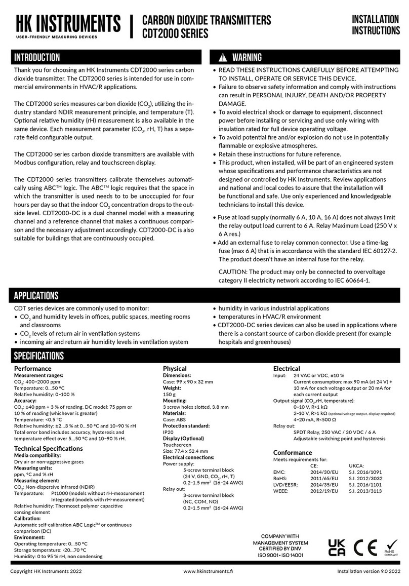
HK Instruments CDT 2000 Duct Series User manual
HK Instruments
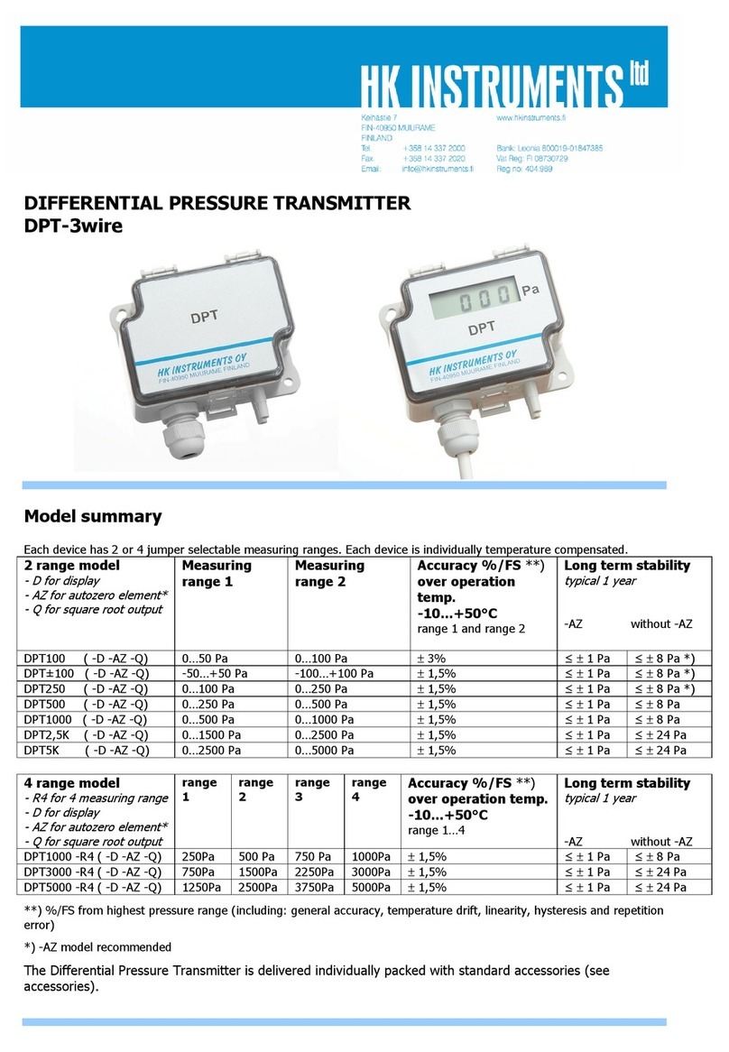
HK Instruments CDT2000 Series User manual
HK Instruments
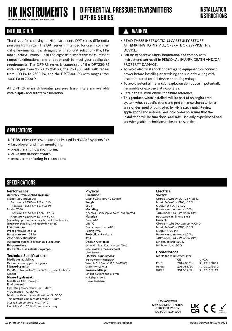
HK Instruments DPT100 User manual
HK Instruments
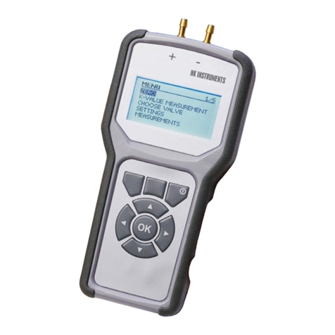
HK Instruments DPT-R8 Series User manual
HK Instruments
HK Instruments PHM-V1 User manual

HK Instruments
HK Instruments DPG Series User manual
