Coemar Panorama Cyc 250 C. User manual

1st edition, ma
y
2002
instructions
manual

Index
1. Packaging Pag. 3
2.Transportation ,, 3
3.Important safety information ,, 3
4.Opening the projector ,, 4
5.Lamp: installation and replacement ,, 5
6.Operating voltage and frequency ,, 7
7.Installation ,, 7
7.1 Installing the unit in weather protected areas ,, 7
7.2 Installing the unit in exposed areas ,, 7
7.3 Warning ,, 7
8.Mains connection ,, 8
9.Signal connection ,, 9
9.1 Automated operation - “solo” ,, 9
9.2 Operation via DMX 512 ,, 9
9.3 Synchronising multiple Panorama fixtures without DMX 512 signal ,, 10
10.Powering up ,, 11
11.DMX addressing ,, 12
12.Operating via DMX 512 signal ,, 13
13.Dip-switches settings for automated “solo” operation ,, 14
14.Operating multiple Panorama Cyc 250 C. in the absence of DMX signal ,, 15
14.1 “Master” units ,, 15
14.2 “Slave” units ,, 16
15.Dip-switch functions ,, 17
16.Remote operation using “dr1”,, 18
17.Auxiliary led and reset button functions ,, 19
18.Mechanical adjustments ,, 20
18.1 Tilt adjustment ,, 20
18.2 Altering beam angles by inserting diffusion filters ,, 21
19.Altering the operating voltage and frequency ,, 23
19.1 Selecting the operating voltage on the autotransformer ,, 23
19.2 Selecting the operating frequency on the power supply ,, 24
20.Opening the front of the projector ,, 25
21.Thermal protection ,, 27
22.Servo-controlled fan ,, 27
23.Maintenance ,, 27
24.Electronic motor alignment ,, 28
25.Spare parts ,, 29
2
English

Congratulations on having purchased a coemar product. You have assured yourself of a fixture of the highest quality, both in com-
ponentry and in the technology used. We renew our invitation to you to complete the service information on the previous page, to
expedite any request for service information or spares (in case of problems encountered either during, or subsequent to, installation).
This information will assist in providing prompt and accurate advice from your coemar service centre.
Following the instructions and procedures outlined in this manual will ensure the maximum efficiency of this product for years to
come.
Open the packaging and ensure that no part of the equipment has suffered damage in transit. In case of damage to the equipment,
contact your carrier immediately by telephone or fax, following this with formal notification in writing.
packing list
Ensure the packaging contains:
1 Panorama Cyc 250 C.
1 instruction manual
3 optical prismatic lenses
The Panorama Cyc 250 C. should be transported in its original packaging or in a coemar approved flight case.
During transportation, the packaging or flight case should ensure no movement of the unit.
Failure to do so may result in damage to the unit.
Fire prevention:
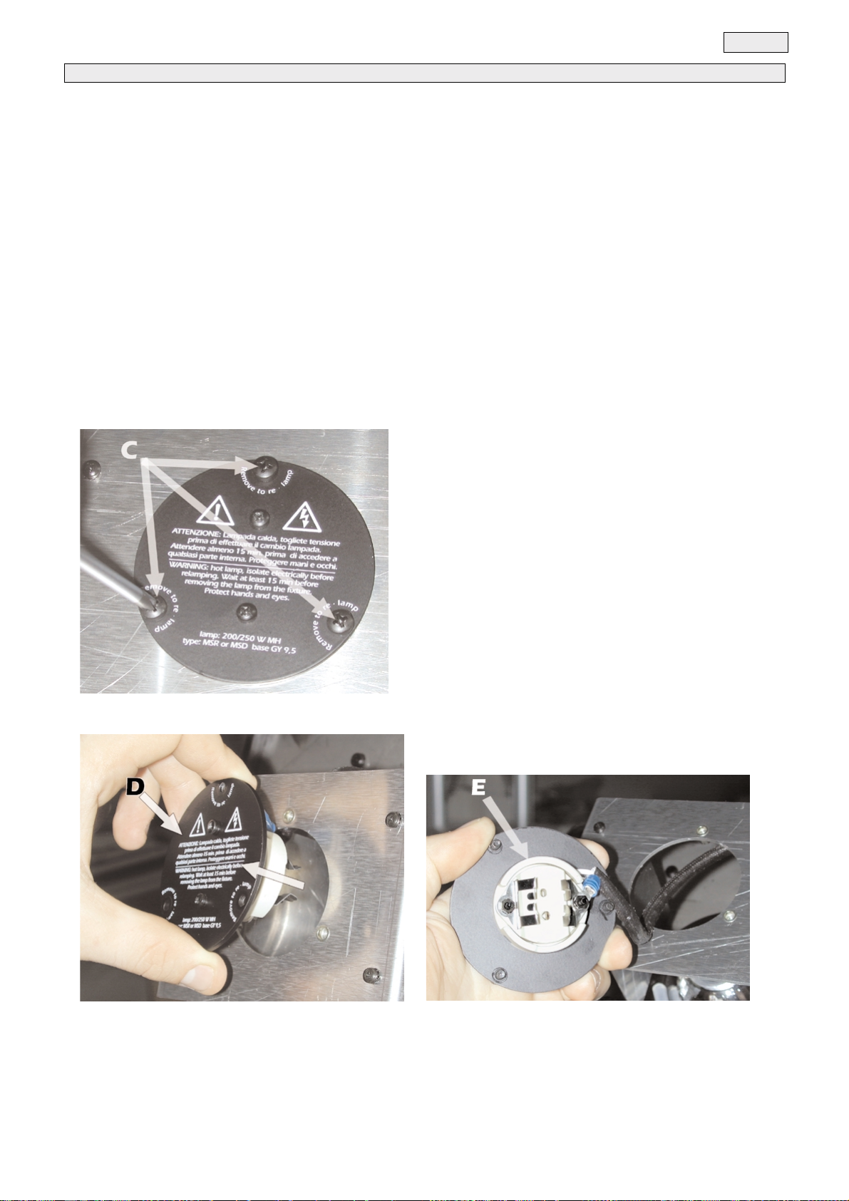
1. Panorama Cyc 250 C utilises a Philips MSD 250W/2 lamp or equivalent; the use of any other lamp is not recommended and
will null and void the fixture’s warranty.
2. Never locate the fixture on any flammable surface.
3. Minimum distance from flammable materials: 0,5 m.
4. Minimum distance from the closest illuminable surface: 2 m.
5. Replace any blown or damaged fuses only with those of identical values. Refer to the schematic diagram if there is any doubt.
6. Connect the projector to mains power via a thermal magnetic circuit breaker.
Prevention against electric shock
1. High voltage is present in the internals of the unit. Isolate the projector from mains supply prior to performing any function which
involves touching the internals of the unit, including lamp replacement.
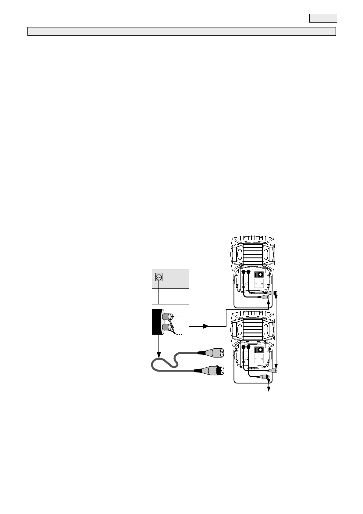
2. For mains connection, adhere strictly to the guidelines outlined in section 7 of this manual.
3. The level of technology inherent in the Panorama Cyc 250 C requires the use of specialised personnel for all service applica-
tions; refer all work to your authorised coemar service centre.
4. A good earth connection is essential for proper functioning of the projector.
Never operate the unit without proper earth connection.
Protection against ultraviolet radiation
1. Never turn on the lamp if any of the lenses, filters, or the housing is damaged; their respective functions will only operate efficiently
if they are in perfect working order.
2. Never look directly into the lamp when it is operating.
Safety:
1. The projector should always be installed with bolts, clamps, and other fixings which are suitably rated to support the weight of
the unit.
2. Always use a secondary safety chain of a suitable rating to sustain the weight of the unit in case of the failure of the primary fixing
point.
3. The external surface of the unit, at various points, may exceed 150°C. Never handle the unit until at least 8 minutes have elap-
sed since the lamp was turned off.
4. Never install the fixture where unauthorised and untrained personnel may tamper with it.
5. Always replace the lamp if any physical damage is evident.
6. Never install the fixture in an enclosed area lacking sufficient air flow; the ambient temperature should not exceed 35°C.
7. A hot lamp may explode. always wait for at least 8 minutes to elapse after the unit has been turned off prior to attempting to
replace the lamp. Always wear suitable hand protection when handling the lamp.
Protection rating of the body against liquids and solids:
1. The fixture has an IP 44 protection rating; this indicates that a particle larger than Ø 1 mm cannot penetrate the unit and that it is
totally protected against showers of water.
The protection rating allows the fixture to be utilised in an exposed location in inclement weather as long as it is installed according
to the instructions located in section 7.2 “Installing the unit in exposed areas”.
3. Important safety information
2. Transportation
1. Packaging
3
English

Many of the operations described later in this manual can only be performed with the projector housing opened..
To access the internals of the projector, proceed as follows:
1) Using a Philips head screwdriver, loosen and remove the 11 screws (A) which affix the rear housing (B) of the projector body.
Care should be taken during this operation to not drop and lose the screws.
2) Remove the cover (B) from the central seal.
3)You should now have access to the internals of the unit and may carry out the instructions detailed below.
Important Note:
To close the unit, you must ensure that the rear cover (B) is properly seated in the central seal (C) and then replace and
fasten the 11 screws. The Panorama Cyc 250 C will only maintain its weather-resistance if this procedure is carried out
with scrupulous attention to detail.
Attention!
Turn off the power prior to opening up the unit.
The fixture’s internal temperature may reach 250° C after 5 minutes, with a maximum peak of 350°C.Ensure the lamp is cold
prior to attempting removal. The fixture should be allowed to stand and cool for 10 minutes prior to its removal.
4. Opening the projector
4
English

The Panorama Cyc 250 C utilises a Philips MSD 250W or Philips MSD 250W/2 lamp or equivalent.
The lamp is available from your authorised coemar sales agent:
coemar code 105214/1
power 250 w
luminous flux 18.000 lm
colour temperature 8.500° K
base GY 9,5
approximate lamp life 2000 hours
coemar code 105214
power 250 w
luminous flux 18.000 lm
colour temperature 6.700° K
base GY 9,5
approximate lamp life 2000 hours
To access the lamp, you should proceed as described in section 4 of this manual.
MSD lamps are part of the mercury vapour family of discharge lamps and must be handled with great care. the lamp operates at
high pressure, and the slight risk of explosion of the lamp exists if operated over its recommended life.
We recommend, therefore, that the lamp be replaced within the manufacturer’s specified lamp life.
1) Locate the lamp assembly and, using a Philips head screwdriver, loosen the three screws (C) which affix the assembly.
2) Remove the lamp assembly (D). Care should be taken to avoid damaging the cables when extracting the assembly.
3) Locate the lampholder (E)
5. Lamp: installation and replacement
5
English

4) Insert the lamp into its base (E).
The lamp used is manufactured from quartz glass and should be handled with care. Always adhere to the instructions supplied in
the lamp’s packaging. Do not touch the glass directly, use the cloth provided with the lamp.The GY 9,5 lampholder is asymmetrical
in construction, with one pin larger than the other. Ensure that the pins are correctly aligned with the appropriate socket. DO NOT
USE UNDUE FORCE. Incase of difficulty, re-read the instructions and repeat the procedure.
5) Replace the lamp into its original position and replace and retigh-
ten the 3 screws which were previously removed.
Do not close the unit until all the operations have been performed on the display panel internal to the Panorama Cyc 250 C.
6
English

The fixture may operate at voltages ranging from 100-115-208, 230 or 240V .at 50 or 60 Hz; coemar factory presets (barring spe-
cific requests), a voltage of 230v and a frequency of 50 Hz. This preset is indicated on the sticker located on the base of the projec-
tor, as indicated in the following diagram.
If the specified voltage and frequency do not match those of the country in which you are operating, follow the instructions in sec-
tion 19 of this manual. “Altering the operating voltage and frequency”
Incorrect voltage and frequency selection will detrimentally affect the operation of the projector.
Due to its high protection rating Panorama Cyc 250 C may be installed in a variety of locations, both indoors and in areas expo-
sed to the elements.
7.1 Installing the unit in weather protected areas.
Panorama Cyc 250 C. may be situated in any mounting position when operated in sheltered areas.
In order to allow it to be installed in a variety of locations, the Panorama Cyc 250 is provided with 5 mounting holes (A) of Ø 13mm
on its base; for permanent and secure mounting on any surface.
If hanging the unit from ceiling or a structure, you may utilise the holes (A) which allow for the attachment of a “c” clamp at any posi-
tion through 360°. The structure from which the unit is hung should be of sufficient rating to hold the weight of the unit, as should
any clamps used to hand the unit.
7.2 Installing the unit in exposed areas
The Panorama Cyc 250 C may be situated in several mounting positions when installed in an exposed area, thanks to its IP 44
protection rating. To ensure proper installation, however, there is a simple guideline to follow:
Installing the unit incorrectly may cause damage to occur and will immediately void the warranty.
Attention!
As shown in the diagram, base of the unit must always be facing the ground.
The Panorama Cyc 250 C may be adjusted from -45° to +90°.without having to move any other component except the head
of the fixture.. Installation in any position other than with the base down, will cause the projector to not perform with its maximum
protection rating, although, with adequate covering, it may operate in almost any position.
175mm
6,90”
120mm
4,72”
==
325mm
12,80”
7. Installation
factory set
main at:
100V
115V
208V
230V
240V
50Hz
60Hz
6. Operating voltage and frequency
7
English

7.3 Warning
safety chain
When hanging the Panorama Cyc 250 C we recommend the use of a safety chain (cod. 069), affixed to the appropriate hole
(B) on the yoke of the Panorama Cyc 250 C and to the suspension device.
This secondary safety attachment should be done using either a metal wire rope or a metal chain, both suitably rated for the pur-
pose.
risk of fire
Every projector produces head, and should therefore be installed in a well-ventilated position. The minimum distance from flamma-
ble materials: 0,5m. The minimum distance from the object being illuminated: 2 m.
cabling
The mains cable provided is thermally resistant, complying to the most recent international standards.
NB: In case of cable replacement, similar cable with comparable thermal resistant qualities must be used exclusively (cable 3x1.5 ø exter-
nal 10 mm, rated 300/500V, tested to 2KV, operating temperature -40° +180°. coemar cod. CV5309).
mains connection
Panorama Cyc 250 C can operate at voltages from 100V-115V-208V-230V-240V at 50 or 60Hz (operating voltage and
frequency can be selected as described in section 6 and 19 of this manual). Prior to connecting the unit to your mains supply, ensu-
re that the model in your possession correctly matches the mains supply available to you.
For connection purposes, ensure your plug is of a suitable rating:
at 230 V: 2 Amps on startup, 1,6 amps constant draw in normal operation
a 115 V: 4,2 Amps on startup, 3,2 amps constant draw in normal operation
Locate the mains cable which exits the base of the unit and connect as shown below:
protection
The use of a thermal magnetic circuit breaker is recommended for each Panorama Cyc 250 C.
A good earth connection is essential for the correct operation of the fixture. Strict adherence to regulatory norms is strongly recom-
mended.
Panorama Cyc 250 C. must be earthed; never install the unit unless the yellow/green earth cable is secu-
rely connected.
massa/ground
neutro/neutral
fase/live marrone - brown
blu - blue
giallo/verde - yellow/green
alimentazione
main
8. Mains connection
8
English

Panorama Cyc 250 C. may operate in 3 different modes:
9.1 Automated operation
9.2 Using DMX 512 signal
9.3 Synchronising Panorama Cyc 250 C without DMX 512 signal.
Follow the instructions below which relate to your particular application:
9.1 Automated operation “solo”
Panorama Cyc 250 C. may operate in stand alone mode in the absence of control signal, using pre-program-
med colour changing sequence which can be activated by the dip-switches on the rear panel of the unit.
No incoming signal to the XLR3 sockets should be connected.
We recommend that the XLR 3 sockets be isolated by unscrewing the 3 cables from the rear of the sockets marked DMX IN and
DMX OUT or by using suitably sheathed weather-proof dummy plugs.
This ensures that the weather rating of the Panorama Cyc 250 C..
9.2 Using DMX 512 signal
Control signal is digital, and is transmitted via two pair screened ø0.5mm cable.
Connection is serial, utilising the XLR 3 sockets located on the base of the Panorama Cyc 250 C.
coemar supplies with the unit XLR 3 connectors with an IP 67 protection rating; use only similar plugs for the connection of signal
to the unit, thereby ensuring that the protection rating of the unit is maintained.
coemar code for the IP 67 rated XLR3 socket is ME 34
coemar code for the IP 67 rated XLR3 plug is ME 35
We recommend isolating the XLR 3 socket which terminates you dmx daisy chain.
To isolate the connector (which is the only one without a plug inserted) you may internally disconnect the cabling from the socket
indicated by the DMX OUT sticker.
Only by isolating the final socket will the protection rating of the unit be preserved.Panorama Cyc 250 C..
signal connection
Connection is to international standards:
pin 1= gnd
pin 2= data –
pin 3= data +
Ensure that all data conductors are isolated from one another and the metal housing of the connector.
Note: the housing of the XLR 3 must be isolated.
Pin 1 should never be connected to mains power.
Should your DMX 512 controller output via an XLR 5 socket, the polarity of pins 1, 2 and 3 must be maintained and pins 4 and 5
should remain unconnected.
factory set
main at:
100V
115V
208V
230V
240V
50Hz
60Hz
madein italy by
coemarspa
CastelGoffredo (mn)
Attenzione!
Altatensione all'interno dell'apparecchio. Togliere
tensioneprima di effettuare qualsiasi operazione.
Unabuona connessione di terra e' essenziale.
Contenitoremolto caldo. Non installare su alcuna
superficieinfiammabile. Distanza minima da
materialeinfiammabile: 0,5m. Prima di accendere
l'apparecchioe' indispensabile leggere il manuale
diistruzioni; importanti
informazionidi
sicurezza.
Warning!
Highvoltage inside.
Caution:hot lamp. Disconnect
frompower supply before opening.
Agood ground connection is essential.
Caseis very hot. Do not install on flammable
surfaces.Min. Distance from flammable materials
toall exterior surfaces:0,5m. Important safety
information,see instruction manual before use.
DMX OUT DMX IN
230v
iemax: 2A
ie:1,6A
maxtemp ext:
150°C
ta max:
35°C
cos
ϕ:
0,85
IP 44
2 m
2 m
alto/top
115v
iemax: 4,2A
ie:3,2A
Weight:Kg 16,5
3 pin XLR 3/M
3 pin XLR 3/F
out
in
out
factory set
main at:
100V
115V
208V
230V
240V
50Hz
60Hz
madein italy by
coemarspa
CastelGoffredo (mn)
Attenzione!
Altatensione all'interno dell'apparecchio. Togliere
tensioneprima di effettuare qualsiasi operazione.
Unabuona connessione di terra e' essenziale.
Contenitoremolto caldo. Non installare su alcuna
superficieinfiammabile. Distanza minima da
materialeinfiammabile: 0,5m. Prima di accendere
l'apparecchioe' indispensabile leggere il manuale
diistruzioni; importanti
informazionidi
sicurezza.
Warning!
Highvoltage inside.
Caution:hot lamp. Disconnect
frompower supply before opening.
Agood ground connection is essential.
Caseis very hot. Do not install on flammable
surfaces.Min. Distance from flammable materials
toall exterior surfaces:0,5m. Important safety
information,see instruction manual before use.
DMX OUT DMX IN
230v
iemax: 2A
ie:1,6A
maxtemp ext:
150°C
ta max:
35°C
cos
ϕ:
0,85
IP 44
2 m
2 m
alto/top
115v
iemax: 4,2A
ie:3,2A
Weight:Kg 16,5
in
Controller
DMX 512
OUT
3
2
1
Ad altri Panorama Cyc 250 C.
Connect to other Panorama Cyc 250 C.
9. Signal connection
9
English

9.3 Synchronising Panorama Cyc 250 without DMX 512 signal.
Multiple Panorama Cyc 250 C units may be interconnected in the absence of DMX 512 signal, operating simply via the inbuilt
programs within the Panorama Cyc 250 C.
All Panorama Cyc 250 Cs thus connected will operate simultaneously with one unit acting as MASTER and all subse-
quent units as a SLAVES.
Determine which of the Panorama Cyc 250 C will act as master, usually by the criterion of ease of access:
coemar code for the IP 67 rated XLR3 socket is ME 34
coemar code for the IP 67 rated XLR3 plug is ME 35
Connection should be to international standards:
pin 1= gnd
pin 2= data –
pin 3= data +
Ensure that all data conductors are isolated from one another and the
metal housing of the connector.
Pin 1 should never be connected to mains power.
factory set
main at:
100V
115V
208V
230V
240V
50Hz
60Hz
made in italy by
coemar spa
Castel Goffredo(mn)
Attenzione!
Altatensione all'interno dell'apparecchio. Togliere
tensioneprima di effettuare qualsiasi operazione.
Unabuona connessione di terra e' essenziale.
Contenitoremolto caldo. Non installare su alcuna
superficieinfiammabile. Distanza minima da
materialeinfiammabile: 0,5m. Prima di accendere
l'apparecchioe' indispensabile leggere il manuale
diistruzioni; importanti
informazionidi
sicurezza.
Warning!
Highvoltage inside.
Caution:hot lamp. Disconnect
frompower supply before opening.
Agood ground connection is essential.
Caseis very hot. Do not install on flammable
surfaces.Min. Distance from flammable materials
toall exterior surfaces:0,5m. Important safety
information,see instruction manual before use.
DMX OUTDMX IN
230v
iemax: 2A
ie: 1,6A
max temp ext:
150°C
ta max:
35°C
cos
ϕ:
0,85
IP 44
2 m
2 m
alto/top
115v
iemax: 4,2A
ie: 3,2A
Weight: Kg 16,5
out
out
in
master
slave
in
Ad altri Panorama Cyc 250 C. (slave)
Connect to other Panorama Cyc 250 C. (slave)
10
English

To perform the operations which follow, from sections 10 to 16, with the exception of 15, the projector housing should be open. If
you have since closed the unit up, reopen the housing as described in section 4.
After having followed the preceding steps, turn on the power to the unit.
If you have chosen to control the Panorama Cyc 250 C using a DMX 512 controller, you should always turn on the power to the
controller first.
The fixture will perform a reset function on its internal motors. This will last some few seconds, after which it will be subject to the
external signal from the controller.
Ventilation
The projector is fitted with 2 fans for forced cooling of the unit.
The two fans are directly controlled by the on-board software and may be switched off on powering up, depending upon the set-
tings of the unit’s dip switches. They may never be switched off when the lamp is turned on.
To turn the fans on, you will need to switch on the lamp or alter the fan dip switch setting to ON..
DMX 512 signal reception
Upon being powered up, the projector will proceed with its reset function. On completion of this, the led will flash if the projector
is correctly receiving DMX 512 signal.
If the led remains off, the projector is not receiving signal correctly. Check the cabling and the functioning of the controller.
turning on the power with no dmx signal connected
After being powered up, the projector will perform a reset. When completed, the led will remain off, indicating that the fixture is not
receiving DMX 512 control signal.
fan
alert lamp
status DMX
ON ON
reset
dip-switches
1 2 4 8 16 32 64 128 256
PR 1 PR 2 PR 3 PR 4 T 1 T 2 SP 1 SP2 all PR
DMX addresses, ID personality or built in program and speed
OFF - DMX addressing, ID personality
ON - built in program control
test fan ON lamp ON DR1
remote
motor
calibration colour
mode inhibit
all OFF for slave
10. Powering up
Important Information
11
English

Each Panorama Cyc 250 C utilises 4 channels of DMX signal for complete control of all its functions.
To ensure that each unit accesses the correct signal, it is necessary to correctly address each fixture. Any number between 1 and 508
can be generated via the dip-switches of the Panorama Cyc 250 C..
This procedure must be carried out on every unit being utilised, positioning the dip-switches to either ON or OFF depending upon
what DMX address is required.
The DMX address of a particular projector is the sum total of the dip-switches settings, for example:
DMX 42 is obtained by switching the dip-switches values 32+8+2 to ON
DMX 82 is obtained by switching the dip-switches values 64+16+2 to ON
The diagram below shows how to set the dip switches to their ON position, setting the address to DMX 1.Obviously, any DMX
address can be achieved by adding together the values achieved when switching on the respective dip switches.
es. dmx address n° 1
The first projector will utilise DMX address 1; a projector thus addressed will respond to commands on channels 1to 4from the
DMX 512 controller. A second projector should be addressed as 5a third as 9and so on until the final unit has been addressed.
Ensure that none of the DMX values you assign overlap. This will ensure that each projector can have all its functions individually
addressed by the console.
To learn further about the individual operation of each function of the Panorama Cyc 250 C, refer to section 12 of this
manual“Operating via DMX 512 signal”.
ON
dip-switches
1248163264128256
11. DMX addressing
12
English

Panorama Cyc 250 C is able to operate via DMX 512 signal. Connection should be as described as in section ”9.2 Operation
via DMX 512 signal”.
If the instructions in this manual have been carried out to this point, the 6 channels of your DMX 512 controller will have con-
trol over all the functions of the Panorama Cyc 250 C as shown in the following table.:
to ignite the lamp
to ignite the lamp channel 4 must have a value between 242 and 255; to turn it off, channel 4 must have a value between 11 and
30. you can force the lamp to ignite setting on ON the lamp on.dip switch
Once the lamp is on, the lamp status led lights up.
ON ON
lamp ON
channel
function type of control effect decimal
1colours step Open/white 0-24
step or proportional
depending on
channel 2
colour 1 24-49
step or proportional
depending on
channel 2
colour 2 50-74
step or proportional
depending on
channel 2
colour 3 75-99
step or proportional
depending on
channel 2
colour 4 100-127
proportional Forwards rainbow effect from fast to slow 128-190
step No rotation 191-192
proportional Backwards rainbow effect from slow to fast 193-255
2colour mode step colours (channel 1) steps 0-127
step colours (channel 1) proportional 128-255
3 Auto function step No effects 0-9
proportional Auto program 1 (color sequence without white) speed from fast to slow 10-61
proportional Auto program 2 (full color sequence) speed from fast to slow 62-113
proportional Auto program 3 (color sequence with half color) speed from fast to slow 114-165
proportional
Auto program 4 (color sequence including continuos rotation, speed from fast to
slow)
166-217
step Random program 218-240
step All programs 241-255
4
Lamp on/off/
reset
step Park (no function) 0-10
program wait
time control
step lamp off 11-30
step motor reset (only once) 31-60
step Program stop 61-80
proportional Selected auto-program pause time control (1 sec/5 min) 81-241
step lamp on 242-255
Dip-switches can inhibit lamp off function
note 1: lamp on/off and reset have a delay time of 6 second to prevent accidental activation.
note 2 :on/off lamp mode is not affected unless an opposite value is received
note 3 :Dip-switch 14 ON change channel 3 function
12. Operating via DMX 512 signal
13
English

Panorama Cyc 250 C can operate automatically, running a series of internally recorded programs whose settings are determined
by the dip switch settings imposed by the operator.
No signal cable should be connected to the fixtures XLR3 sockets, as described in section 9.1 “Signal con-
nection for automated “solo” operation”.
Activating automated operation
Set to ON the dip-switch named On-built in program control. From this moment, the dip-switches 1 to 9 may be used to adjust
the various parameters for automated colour changes: program selection, fade times and speed.
Selecting automated colour change programs.
Dip-switches from PR1 to PR4 (program 1 to program 4), when switched to the ON position, activate preset colour change
programs.
The 4 in-built programs have the following features:
Program 1: all colours, with the exception of open white, in a smooth, slow crossfade sequence
Program 2: all colours in a smooth, slow crossfade sequence
Program 3: all colours, with the exception of open white, in sequence.
Program 4: all colours in sequence.
Selecting the hold time
Dip-switches T1 and T2 allow for one of 4 hold times for the various colours
Selecting the fade speed
Dip-switches SP1 and SP2 allow for one of 4 fade times to be selected:
All programs in continuous sequence
Dip switch All PR in the ON position allows for all programs to be replayed in sequence automatically and continuously.
SP1 SP2 speed
off off fast
on off medium
off on medium slow
on on slow
T1 T2 t (sec.)
off off 3
on off 10
off on 30
on on 60
Important note:
Only one program at a time may be selected.
ON
ON - built in program control
PR 1 PR 2 PR 3 PR 4 T 1 T 2 SP 1 SP2 all PR
built in program and speed
13. Dip-switch settings for automated “solo” operation.
14
English

Multiple Panorama Cyc 250 C. can be operated in the absence of control signal by executing internally stored, pre-recorded pro-
grams.
Projectors correctly connected together may operate in synchronised mode, the Panorama Cyc 250 C receiving signal being
denominated as “slave” units and those generating control signal designated as “master” units.
To activate this automated function, projectors must be connected together as described in the section entitled 9.3. “Synchronising
multiple Panorama Cyc 250 C fixtures without using DMX 512”; No signal cables should be connected to the external XLR3 soc-
kets.
Power up the projector and use the dip-switches to adjust to the correct settings.
14.1 “Masters”
Panorama Cyc 250 C may operate automatically with output in the form of pre-recorded programs, as described in section “9.3.
Synchronising multiple Panorama Cyc 250 C fixtures without using DMX 512” Only one unit may be designated as
“master”.
Selecting a master unit is simply a matter of convenience and accessibility to the dip-switches:
Activating “auto” mode
Set to ON the dip-switch named On-built in program control. From this moment, the dip-switches 1to 9may be used to adjust
the various parameters for automated colour changes: program selection, fade times and speed.
Selecting automated colour change programs.
Dip-switches from PR1 to PR4 (program 1 to program 4), when switched to the ON position, activate preset colour change
programs.
The 4inbuilt programs have the following features:
Program 1: all colours, with the exception of open white, in a smooth, slow crossfade sequence
Program 2: all colours in a smooth, slow crossfade sequence
Program 3: all colours, with the exception of open white, in sequence.
Program 4: all colours in sequence.
Selecting the hold time
Dip-switches T1 and T2 allow for one of 4hold times for the various colours
Selecting the fade speed
Dip-switches SP1 and SP2 allow for one of 4fade times to be selected.
Important note:
Only one program at a time may be selected.
ON
ON - built in program control
PR 1 PR 2 PR 3 PR 4 T 1 T 2 SP 1 SP2 all PR
built in program and speed
14. Operating multiple Panorama in synchronised mode without DMX 512
15
English

Running programs in a continuous sequence
Setting dip-switches All PR in the ON position causes all the pre-recorded programs to run in an automated continuous sequen-
ce.
14.2 “slaves”
All projectors which are connected to a “Master” unit should be set to “Slave”. Connections should be as described in section “9.3
Synchronising multiple Panorama fixtures without DMX 512”.
“Slave” units are recognisable since they have connections made to both XLR sockets in their base, except for the final unit in the
chain which has only one connection to its “DMX IN”.socket.
To set projectors to “Slave” mode, it is necessary to simply set dip-switches 1to 9in the OFF position and the On-built in
program control dip switch to ON
ON
ON - built in program control
PR 1 PR 2 PR 3 PR 4 T 1 T 2 SP 1 SP2 all PR
DMX addresses, ID personality or built in program and speed
16
English

The control panel of the Panorama Cyc 250 C. is fitted with a further 6 additional dip-switches to those described in sec-
tion 13. These are used to alter several parameters of the unit.
Testing the projector
Setting the test dip-switch to the ON position will cause the Panorama Cyc 250 C to carry out a self-test function.
Fans
Setting the fan dip-switch to the ON position will cause the fans to remain on at all times the projector is powered up. In the OFF
position, the fans will operate only when the lamp is switched on.
Lamp control
With the lamp dip-switch in the ON position, the lamp will remain on at all times the projector is powered up. In the OFF position,
the lamp will be controlled via DMX signal.
Motor calibration
The motor calibration dip-switch in the ON position will allow for motor offsets to be recalibrated.
For further information about this, read section 24. Electronic motor alignment.
Inhibiting colour changes
The colour mode dip-switch will inhibit colour change when in the ON position by over-riding DMX channel 2 (which controls
colour changing).
dr 1 dialog
The dr1 remote dip-switch, when switched to the ON position, allows the dip-switch settings to be by-passed for communication
between the Panorama Cyc 250 C. and the dr 1.
For further information, refer to section 16. Remote operation using the dr1 .
ON ON
DR1
remote
ON ON
colour
mode inhibit
ON ON
motor
calibration
ON ON
lamp ON
ON ON
fan ON
ON ON
test
15. Dip-switch functions
17
English

Panorama CYC 250 C. is compatible with the bidirectional transmission protocol dr1.
Using the dr1 controller (display remote) it is possible to view and alter parameters remotely.
The input code for the dr1 is: PCO9703
The remote parameters available via dr1 are:
Readouts:
1) Fan state
2) Software version
3) Temperature readout
4) Fan speed
5) Lamp life
6) Projector life
7) DMX 512 state and characteristics
8) Error messages
Control:
1) DMX addressing
2) Turning on the lamp
3) Setting Master/Slave state
4) Projector reset
5) Motor testing
6) Automated program operation and parameter settings
7) Motor alignment
To set up the dialog between the Panorama Cyc 250 C. and dr1 you must install it in the DMX 512 line, paying close atten-
tion to the instructions within the unit.
The dr1 remote dip switch must be switched to the ON position. At this point, the dip switches which set from 1 to 128 are
used to set the identity number (ID) of the unit, not the DMX address, which is set by dr1.
The highest ID number accepted by the dr1 system is 250; dip-switch 256 has no function in this operating mode.
The ID number is achieved by summing the individual dip-switch values. For example:
ID 9is achieved by setting dip-switches 3-4-2 to the ON position.
ID 50 is achieved by setting dip-switches 2-32-16 to the ON position.
eg. ID n° 35:
ON ON
dip-switches
1248163264128256 DR1
remote
Nessuna funzione
16. Remote operation using dr1
18
English

Led: Fan alert
The Fan alert led indicates that the fans have malfunctioned:
Led ON: one or other of the fans are not operating - test them separately.
Led OFF: correct fan operation
Led: Lamp status
The lamp status led indicates the lamp functioning:
Led ON: lamp is on
Led OFF: lamp is off
Led: DMX
The DMX led indicates the DMX input state:
Led flashing ON: signal is present
Led OFF: no signal present
Reset button
Pressing the reset button will cause the fixture to effect a reset of its motors.
dip-switches
reset
O
dip-switches
lamp
status
fan
alert
dip-switches
17. Auxiliary led and reset button functions
19
English

After having powered up the projector and having established DMX 512 control or set it to operate automatically, the following
mechanical adjustments should be carried out in order to maximise the output of the projector in its current installation.
18.1 Adjusting tilt angle
Loosen the two adjustment bolts on the sides of the body which allow the body to tilt (+90° -45°).
After having adjusted the unit to the required tilt, firmly tighten both bolts to avoid the unit slipping out of position.
18. Mechanical adjustments
20
English
Table of contents
Other Coemar Outdoor Light manuals
Popular Outdoor Light manuals by other brands

SUNCATCHER
SUNCATCHER SLM-9169 manual

Philips
Philips 168199316 user manual

modway
modway EEI-5611 Assembly instructions

PUK
PUK LANE ROUND 01 Assembly and operating instructions

B-K lighting
B-K lighting HP2 SERIES installation instructions

HEPER
HEPER RHINO ML 1 Module Installation & maintenance instructions