Coemar CF 1200 Hard Edge User manual

CF 1200
2nd edition, november 1999
instruction
manual

CF 1200
numero di serie/serial number
data di acquisto/date of purchase
fornitore/retailer
indirizzo/address
cap/città/suburb
provincia/capital city
stato/state
tel./fax/
Prendete nota, nello spazio apposito, dei dati relativi al modello e al rivenditore del vostro
CF 1200
: in caso di
richiesta di informazioni, pezzi di ricambio, servizi di riparazione o altro ci permetteranno di assistervi con la mas-
sima rapidità e precisione.
Please note in the space provided above the relative service information of the model and the retailer from
whom you purchased your
CF 1200
: This information will assist us in providing spare parts, repairs or in
answering any technical enquiries with the utmost speed and accuracy.
ATTENZIONE: la sicurezza dell’apparecchio è garantita solo con l’uso appropriato delle presenti istruzioni, per-
tanto è necessario conservarle.
WARNING: the security of the fixture is granted only if these instructions are strictly followed; therefore it is
absolutely necessary to keep this manual.
514 mm
692 mm
750 mm
204 mm
306 mm
592 mm 546 mm

Index
1. Packaging
2.Transporting
3.Important safety information
4. Lamp: installation and replacement
5. Operating voltage and frequency
6. Mounting the unit
7. Mains connection
8. Signal connection
9.Powering up
10.DMX addressing
11.Display panel functions
11.1. Powering up the CF 1200 with movement disenabled
12.Control channel functions from a DMX 512 controller
13.Aligning the lamp in the optical system
14.Interchanging dichroic colours on the colour wheel
15.Automatic internal functions
16.Maintenance
17.Electronic alignment of the motors
18.Spare parts

Congratulations on having purchased a new coemar product; you have assured yourself of a fixture of the highest quality,
both in the components used and in the technology. We renew our request to you to complete the service information on the
preceding page, to expedite any request for information, or for service (in case of problems encountered either during, or sub-
sequent to, installation). This information will assist in prompt and accurate advice from your authorised coemar service centre.
1. Packaging Following the instructions contained in this manual will ensure the maximum effi-
ciency of this product for years to come.
Open the packing and ensure that no part of the equipment has suffered damage in
transit. In the case of damage to the equipment, contact the carrier immediately by
telephone or fax, following this with formal notification in writing.
packing list
Ensure that the packaging contains:
1 CF 1200
1 instruction manual
2. Trasporting The CF 1200 should always be transported in its original packaging or in a coe-
mar approved flight case.
In order to manufacture a suitable flight case, we recommend the following simple
procedures be followed which will stop the articulated movement of the CF 1200
during transportation.
Below are illustrated the 2 diverse methods of padding which coemar recommends.
A) Padding around the entire projector, including the base, with suitable padding
materials.
B) Fixing the base to a rigid support, with padding surrounding the articulated head.
Polietilene
espanso/
Foam
Pomoli di
bloccaggio/
Knobs
Polietilene
espanso/
Foam

3.Important safety Fire prevention
information 1. CF 1200 uses a Philips MSR 1200 SA lamp; the use of any alternative lamp i s
not recommended and will null and void the fixture’s warranty.
2. Never locate the fixture on any flammable surface
3. Minimum distance from flammable materials: 0.5 m.
4. Minimum distance from the closest illuminable surface: 2 m.
5. Replace any blown or damaged fuses only with those of identical values. Refer to
the schematic diagram if there is any doubt.
6. Connect the projector to mains power via a thermal magenetic circuit breaker.
Prevention of electric shock:
1. High voltage is present in the internals of the unit. Isolate the projector from
mains supply prior to performing any function which involves touching the inter-
nal of the unit, including lamp replacement.
2. For mains connection, adhere strictly to the guidelines outlined in section 7 of this
manual.
3. The level of technology inherent in the CF 1200 requires the use of specialised
personnel for all service applications; refer all work to your authorised coemar
service centre.
4. A good earth connection is essential for proper functioning of the projector.
The projector should never be operated without proper earth connection.
5. The fixture should never be located in an exposed position, or in areas of extreme
humidity. A steady supply of circulating air is essential.
Protection against ultraviolet radiation:
1. Never turn on the lamp if any of the lenses, filters, or the carbon fibre housing is
damaged; their respective functions will only occur efficiently if they are in perfect
working order.
Never look directly into the lamp when it is operating.
Safety:
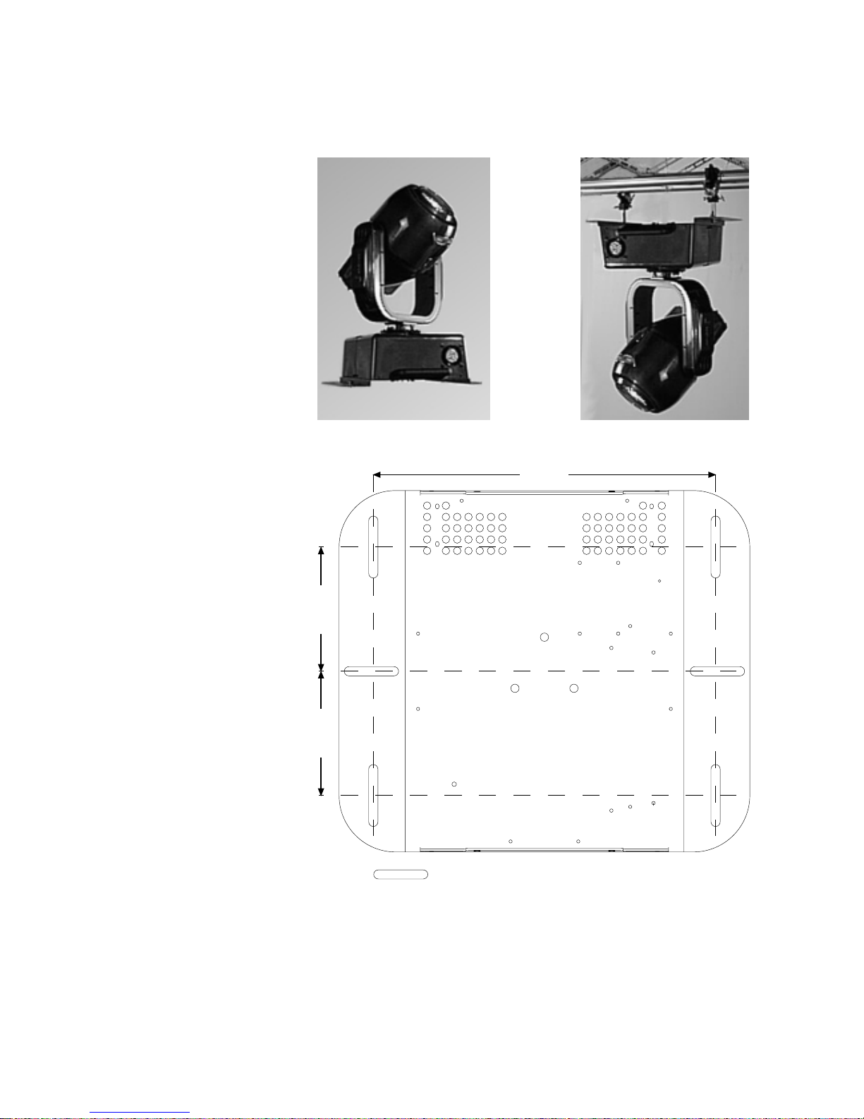
1. The projector should always be installed with bolts, clamps, and other fixings
which are suitably rated to support the weight of the unit.
2. Always use a secondary safety chain of a suitable rating to sustain the weight of
the unit in case of the failure of the primary fixing point.
3. The external surface of the unit, at various points, may exceed 150°C. Never
handle the unit until at least 10 minutes after the lamp has been turned off.
4. Always replace the lamp if any physical damage is evident.
5. Never install the fixture in an enclosed area lacking sufficient air flow; the ambient
temperature should not exceed 35°C.
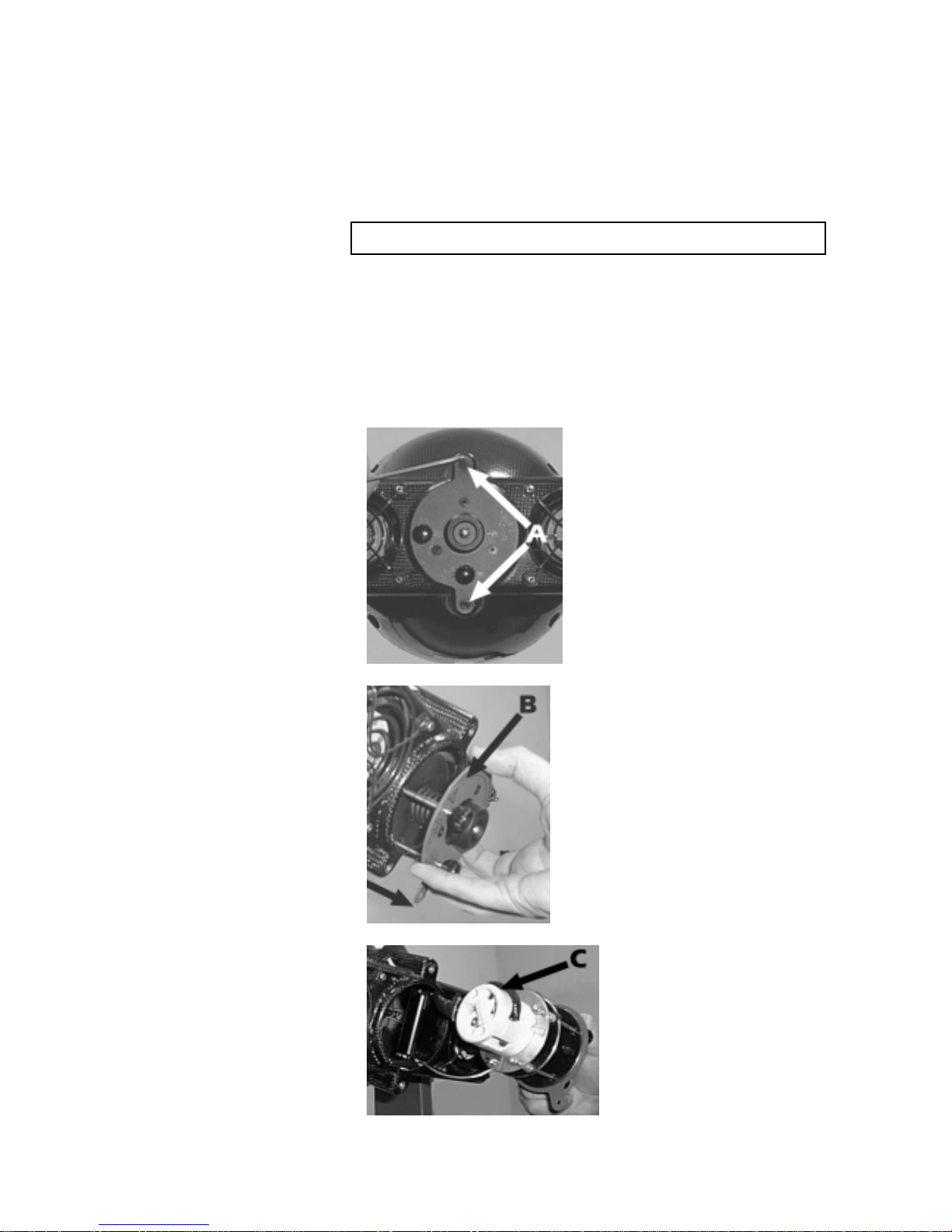
6. The hot lamp may explode, always wait at least 10 minutes after it has been tur-
ned off prior to attempting to replace or handle the lamp.
Always wear suitable hand protection when handling the lamp.

4. Lamp: Installation CF 1200 utilises a 1200 W Philips MSR 1200 SA lamp.
and replacement with a GY 22.lamp base
The lamp is available from your authorised coemar sales agents:
coemar cod. 105090/1
wattage 1200 w
luminous flux 96.000 lm
colour temperature 6500° K
base GY 22
approximate life 500 hours
The fixture’s internal temperature can reach 250° C after 5 minutes, with a maximum
peak of 350° C; ensure that the bulb is cold before attempting removal. The fixture
should be allowed to stand and cool for 10 minutes prior to its removal.
MSR/SA lamps are part of the mercury vapour family of discharge lamps and must be
handled with great care. The lamp operates at high pressure, and the slight risk of
explosion of the lamp exists if operated over its recommended life of 500 hours.
We recommend, therefore, that the lamp be replaced within the manufacturer’s spe-
cified lamp life.
lamp installation
1) With the use of a 3mm Allen Key, loosen the two bolts (A) which fix the lamp
assembly to the body of the projector.
2) Remove the lamp assembly (B).
3) Locate the lampholder (C)
Attention
Disconnect mains power prior to inspecting the unit internally.

4) Insert the lamp (D). The lamp used is manufactured from quartz glass and should
be handled with care; always adhere to the instructions supplied in the lamp’s
packaging. Do not touch the glass directly, the the tissue provided in the lamp
packaging. The GY 22 lampholder is assymetrical in construction. One lamp pin is
larger than the other; therefore make sure that the lamp’s pins are correctly ali-
gned in the lampbase. If you encounter difficulty during this operation, DO NO
USE UNDUE FORCE. Re-read the instructions and repeat the procedure.
5) Replace the lamp assembly (B) in its original position and replace the two bolts
(A) which were previously removed.
Attention: we recommend that the lamp be realigned in the optical train of the
unit to avoid overheating the dichroic filters within the unit; refer to section 13 for
instructions about this procedure.

5. Operating voltage coemar factory presets (barring specific requests), a voltage of 230v to 240v
and frequency selectable via a switch on the base of the CF 1200.
Remember to set the selector (230 or 240V) to the selection which most closely matches
the operating voltage at your venue.
If your operating voltage is 208V, this may be selected internally by shifting the cable
labelled 21 (connected to the 240V position of the switch) or cable 22 (connected to
the 230V switch), thereby, however, eliminating the ability to select either 230V or
240V.
Incorrect voltage selection will detrimentally affect the operation of
the projector. Under no circumstances should cable 23 be moved.
CF 1200 is fitted with an electronic ballast which automatically adjusts the output
voltage to the projector when the input voltage is in the range of 180 to 260V; it is
therefore not necessary to make any modifications when moving to venues with
power supplies in this range.
115V
208V
230V
240V
23
Bianco/White
Nero/black 230V
Rosso/red 115 V
Blu/blue 240V
Giallo/yellow 208 V
22
21
c
oemar set
main at:
115V
208V
230V
240V
230V
coemar set
main at:
115V
208V
230V
240V
240V

6. Mounting the unit mounting
CF 1200 may be floor or ceiling mounted. The structure from which the unit is
hung should be of sufficient rating to hold the weight of the unit, as should any
clamps used to hang the unit.
The structure should also be sufficiently rigid so as not to move or shake whilst the
CF 1200 moves during its operation.
The mouting holes in the base of the unit allow it to be mounted at various angles to
the mounting truss, and to trusses of various dimensions.
The following is a diagram of the base of the CF 1200 Spot.
165mm
165mm
455mm
n°6 asole 72x12 mm r= 6 mm

In order to obtain maximum efficiency of movement, the unit should be mounted
with the ” Front” label facing the main illumination point.
protection against liquids
The projector contains electric and electronic components that must not come into
contact with water, oil, or any other liquid.
moviment
The projector has a movement of 370° in the base and 270° in the yoke; DO NOT
place any obstructions in the path of the projector’s movements.
safety chain
The use of a safety chain (cod. 069) - fixed to the CF 1200 and to the primary
suspension point, is highly recommended to protect against accidental failure,
however unlikely, of the primary suspension point.
If using an after-market safety chain, not manufactured by coemar, ensure that it is
of sufficient strength to hold the weight of this fixture.
risk of fire
Each fixture produces heat and must be installed in a well-ventilated position. The
minimum recommended distance from flammable material is: 0.5m. Minimum
distance from the object being illuminated is: 2m.

7. Mains connection cabling
The mains cable provided is thermally resistant, complying to the most recent inter-
national standards. It meets or exceeds the VDE and IEC norms, IEC 331, IEC 332
3C, CEI 20 35.
NB: In the case of cable replacement, similar cable, with comparable thermal resi-
stant qualities must be used exclusivelly (cable 3x1,5 ø external 10 mm, rated
300/500V, tested to 2KV, operating temperature -40° +180°, coemar cod.
CV5309).
mains connection
CF 1200 can operate at voltages from 208V-230V-240V at 50 or 60Hz (operating
voltage and frequency can be selected as described in section 5 of this manual).
Prior to connecting the unit to your mains supply, ensure that the model in your pos-
session correctly matches the mains supply available to you.
For connection purposes, ensure your plug is of a suitable rating: 9,5 amps.
Locate the mains cable which exits the base of the unit and connect as shown
below:
marrone - brown
blu - blue
giallo/verde - yellow/green
marrone - brown
blu - blue
giallo/verde - yellow/green
massa
ground
neutro
neutral
fase
phase
alimentazione
main
marrone - brown
blu - blue
giallo/verde - yellow/green

protection
The unse of s thermal magnetic circuit breaker is recommended for each CF 1200.
A good earth connection is essential for the correct operation of the fixture. Strict
adherance to regulatory norms is strongly recommended.
ATTENTION!, DANGER!
The electronic ballast with which the CF 1200 is fitted, as with other electronic
devices, requires a correct dimension for the neutral conductor, since the current in
the neutral conductor is equal to the sum of the current in all the active conductors.
For example, if at the mains outlet a current of 10Amps is on phase R, 10Amps on
phase S, and 10Amps on phase T, a total current of 30 Amps exists in the netural.
Please note the above to ensure the correct selection of cable dimensions. Qualified
electrical personnel should always be consulted.
CF 1200 Spot requires a proper earth connection to operate
safely and correctly. Never operate the fixture unless the
green/yellow conductor is connected.

8. Signal connection Control signal is digital and is transmitted via two pair screened ø 0,5mm cable.
Connection is serial, using the XLR 3 or XLR5 male and female sockets set on the rear
part of the CF 1200, labelled DMX 512 and DMX 512 standard (see diagram).
Connection is to international standards:
pin 1= screening 0 volts pin 4= not connected
pin 2= data - pin 5= not connected
pin 3= data +
A connection via 5 Pin XLR 5
Ad altri
CF 1200
Connect to other
CF 1200
3
2
1
Controller
Standard
DMX 512
OUT
in
out
in
out

B connection via 3 Pin XLR 3
Ensure that all data conductors are isolated from one another and the metal housing
of the connector
Make sure that the XLR 3 or 5 pins are isolated form the metal hou-
sing of the cannon connector.
Controller
Standard
DMX 512
OUT
3
2
1
3 pin XLR 3/F
3 pin XLR 3/M Ad altri
CF 1200
Connect to other
CF 1200
out
in
out
in

9. Powering up After having followed the preceding steps, turn on the DMX 512 controller which
will be used to control the CF 1200. Then turn on the power to the projector and
turn on the power switch. The projector will perform a reset function on all the
internal and external motors. This will last some few seconds, after which it will be
subject to the external signal from the controller.
DMX led
The DMX led will be static on to indicate DMX 512 signal is being correctly received
by the projector.
If the led is off, the projector is not receiving signal. Check the cabling and the func-
tioning of the controller.
function display
DMX
menu enter
+
serial number
enter
A001 to A499 13 channels per unit
function display
DMX
menu enter
+
pin1: gnd
pin2: data-
pin3: data+
pin4: optional-
pin5: optional+
in
out
dmx 512
in
out
pin1: gnd
pin2: data-
pin3: data+
dmx 512
standard Set dmx 512 address
Warning!
Electronic ballast, read
instructions carefully before
installing the unit, size of
the neutral must be correct.
240V
T 2A @ 230V
T 4A @ 115V power
T 15A @ 230V
T 25A @ 115V
coemar set
main at:
115V
208V
230V
240V
Attenzione!
Ballast elettronico, leggete
attentamente le istruzioni prima
di installare l'apparecchio,
dimensionate correttamente il neutro.

10. DMX addressing Each CF 1200 utilises 13 channels of DMX 512 signal for complete control.
To ensure that each projector accesses the correct signal, it is necessary to correctly
address each fixture. Any number between 1 and 495 can be generated via the rear
multi-function panel of the CF 1200.
When powered up initally, each projector will display A001 which indicates DMX
address 1; a projector thus addressed will respond to commands on channels 1
through 13 from the DMX 512 controller, a second projector should be addressed
as 14, a third as 27 and so on.
altering DMX addresses
1) Press the +or -buttons until the desired DMX number appears in the LED
display. The display will flash, indicating that the selection is not stored in
memory.
2) Press the enter button to confirm your selection; the display will stop flashing
and the projector will now respond to the new DMX address.
3) To better understand the function of each channel, we refer you to section 12
”Control channel functions from a DMX 512 contoller”.
Important Note: Keeping the +or -pressed down will cause the display to alter at
increased speed, allowing a faster selection to be effected.
By pressing the -button, you may inadvertently select a DMX address which is not
being communicated to by you controller, for example 500; in this case, you will
need to either adjust your controller to ensure the DMX address is being communi-
cated to, or you may need to readjust the DMX addrss of the CF 1200 Spot.
function display
menu
+- enter

11. Display panel The display panel at the rear of the CF 1200 is used to display and set
functions function information and various parameters.
Altering the coemar factory settings may vary the functioning of the projector, cau-
sing it to not respond to external DMX 512 signal. Please read and familiarise your-
self with the following information very carefully before altering any selections.
reset
This function carries out a reset in the case, however unlikely, that one or more
motors lose their reference points.
1) Press the menu button
2) Press the +or -buttons till rESE (for reset) is displayed.
3) Press the enter button to confirm your selection. The projector will proceed to
perform a reset.
rate
This function provides information on the speed or rate of DMX 512 signal being
received by the CF 1200.
1) Press the menu button
2) Press the +or -buttons till rAtE (for rate/speed) is displayed.
3) Press the enter button to confirm; the display will show a numerical value which
is the rate/speed of the DMX 512 signal being received.
hour
This function provides information on the number of hours of operation of the CF
1200.
1) Press the menu button
2) Press the +or -buttons till HoUr (for hour) is displayed.
3) Press the enter button to confirm your selection. The display will show a value
which is the length of time which the fixture has been in operation.
life
This function provides information on the number of hours of operation of the lamp
in the unit.
1) Press the menu button.
2) Press the +or -buttons until LIFE (for lamp life) is displayed.
3) Press the enter button to confirm your selection. The display will show a numeri-
cal value which is the length of time in hours that the lamp has been operated
since the counter was last reset.
resetting the lamp life counter
The lamp life counter needs to be reset to zero at every lamp change to provide
accurate information on lamp life.
1) Turn off the projector.
2) Whilst holding down the +and -buttons, turn power back on to the projector.
3) Press the menu button.
4) Press the +or -buttons until LIFE (for lamp life) is displayed.
function display
menu
+- enter
function display
menu
+- enter
function display
menu
+- enter
function display
menu
+- enter
function display
menu
+- enter

5) Press the enter button to confirm your selection. The display will show 0000,
confirming that the lamp life counter is reset.
dirp
This function inverts the movement for horizontal (pan) movements.
1) Press the menu button.
2) Press the +or -button until dirP (for pan direction) is displayed.
3) Press the enter enter button to confirm your selection. The display will show cW
(for clockwise).
4) Press the +or -until ccW (for counterclockwise) is displayed.
5) Press the enter button after either step 3 or step 4 to confirm your choice of
direction.
dirt
This function inverts the movements for vertical (tilt) movements.
1) Press the menu button.
2) Press the +or -buttons until dirt (for tilt direction) is displayed.
3) Press the enter button to confirm your selection. The display will show cW (for
clockwise).
4) Press the +or -until ccW (for counterclockwise) is displayed.
5) Press the enter button after either step 3 or step 4 to confirm your choice of
direction.
oPto
This function allows the sensors which read the instantaneous pan and tilt positons
of the fixture to be switched on or off.
With the sensors activated (opto ON) the projector will automatically return to its
correct position in case it is accidentaly moved out of position.
With the sensors inactivated (opto OFF) the projector will not return automatically to
its correct position if it is accidentaly moved out of position.
NOTE: there will be a noticable difference in the projector at startup; with opto
ON the reset operation takes but a few seconds; the reset can last up to a minute if
opto oFF is selcted.
1) Press the menu button.
2) Press the +or -buttons until oPto (for optical reader) is displayed.
function display
menu
+- enter
function display
menu
+- enter
function display
menu
+- enter
function display
menu
+- enter
function display
menu
+- enter
function display
menu
+- enter

3) Press the enter button to confirm your selection. The display will show on (for
opto activated).
4) Press the +or -buttons until oFF (opto deactivated) is displayed.
5) Press the enter button to confirm your selection.
N.B. We recommend that the opto be deactivated only if it is obviously defective
and requires replacement.
lamp
This function allows for the on/off control of the lamp via DMX 512 signal, or for
the permanent on (disenabling DMX control of this function) of the lamp.
1) Press the menu button
2) Press the +or -buttons until LAMP (for lamp) is displayed.
3) Press the enter button to confirm your selection. The display will show Strd (for
standard) which corresponds to the standard configuration whereby the lamp
can be turned on remotely by bringing channel 13 up to 100%, or off at 0%.
4) Press the +or -buttons until on (for on) is displayed. At this setting, the lamp will
remain on regardless of the level set on channel 13.
5) Press the enter button to confirm your selection.
coLr
This function allows the colour wheel to be used in a proportional manner via DMX
signal.
1) Press the menu button
2) Press the +or -buttons until coLr (for colour wheel) is displayed.
3) Press the enter button to confirm your selection; the display will show Strd (per
standard) which corresponds to the automatic centring of the colours on the
colour wheel (a change in DMX 512 signal corresponds to a colour change by
the CF 1200.
function display
menu
+- enter
function display
menu
+- enter
function display
menu
+- enter
function display
menu
+- enter
function display
menu
+- enter
unction display
menu
+- enter
function display
menu
+- enter
function display
menu
+- enter

4) Press the +or -buttons; the display will show SPEc (for special) which corre-
sponds to the proportional selection of colours on the colour wheel (split colours
are possible)
5) Press the enter button after either step 3 or step 4 to confirm your choice of
colour selection.
disp
This function inverts the LED display in the display panel, thereby allowing it to be
read easily regardless of the position in which the projector is mounted (see section
6. Mounting the unit).
1) Press the menu button.
2) Press the +or -button until the display shows diSP (for display).
3) Press the enter button to confirm your selection; the display shows AA (for han-
ging position).
4) Press the +or - button; the display shows (for sitting position).
5) Press the enter button after either step 3 or step 4 to confirm your selection.
LEd
This function allows the display to be switched on or off.
1) Press the menu button.
2) Press the +or -button until the display shows Led.
function display
function display
AA
function display
function display
function display
menu
+- enter
Other manuals for CF 1200 Hard Edge
1
Table of contents