EN General Information
4
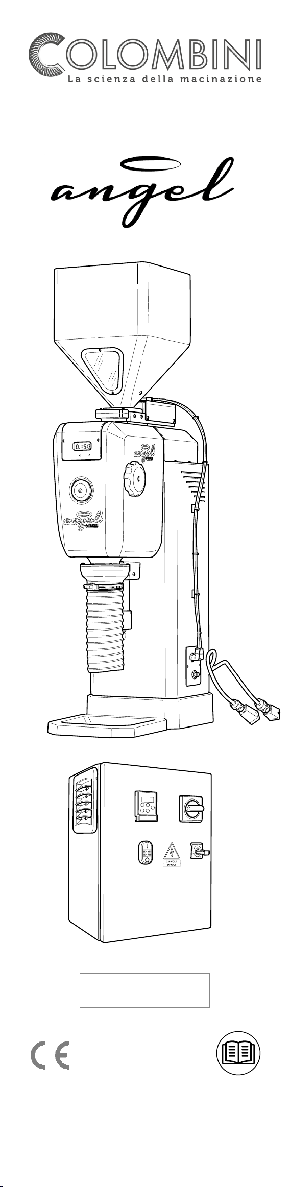
1.1. Machine components
1) Product loading hopper
2) Disc distance display
3) Coupling for connecting compressed air
4) Container support base (for tests)
5) Automatic discharge chute cleaning system
6) Disc distance adjustment wheel
7) Product discharge chute
8) Electric panel connections
1.1.1 Electric panel components
1) INVERTER control
2) START/STOP push button panel
3) STOP IN PROGRESS light
4) Hopper OPENING/CLOSING selector
5) 24 V auxiliary circuit power supply
6) Fuses
7) IG main switch (internal part)
8) Inverter
9) Timers
10) Relays
11) Terminal board
1.2. Manufacturer’s information
COLOMBINI Srl
Via De Francisco 130/16
10036 - SETTIMO TORINESE (TO) - ITALY
Tel. 011.8211407 - Fax 011.8958221
1.3. Messages used
Warning
The WARNING messages indicate a hazard for the
technician including with a high risk. The operations
described following this message must be performed
with extreme care and in conditions of maximum sa-
fety using personal protection equipment.
Caution
The CAUTION messages are displayed before proce-
dures that, if not observed, could cause damage to
the machine.
Environment
The ENVIRONMENT messages are displayed before
procedures that, if not observed, could cause damage
to the environment.
1.4. Intended uses
The Angel grinder has been designed and manu-
factured mainly for grinding roasted coffee.
Suitable for being connected on a specific packaging
machine, the grinder is set up for continuous cycle
processing.
Any incorrect use (not described in these instructions)
and not expressly established with the manufacturer
is prohibited. It is prohibited to make technical mo-
difications. The machine is not intended to be used
by children or people with reduced physical, men-
tal or sensory capacities, or without experience and
knowledge, unless they received instructions related
to use of the machine and are supervised by a person
responsible for their safety.
1.5. Required ambient conditions
To ensure the correct operation of the machine it
must be positioned sheltered from atmospheric
agents (rain, hail, snow, fog, suspended dust, etc.)
with an operating ambient temperature of ≤ 35° C
and relative humidity not greater than 70 %.
The work environment must be clean, sufficiently lu-
minous and without an explosive atmosphere.
1.6. Noise level
The sound power level tests performed on this speci-
fic machine model report a sound pressure less than
70 dB (A).
1.7. Targa di marcatura CE
For any communication with the manufacturer al-
ways quote the information shown on the CE mark-
ing plate
1.7.1 CE marking plate - electric panel
1.8. Technical specifications
Height: 885 mm - Width: 245 mm
Depth: 435 mm - Weight: 50 Kg
Power supply:
ANGEL PG 220V - 50/60 Hz
1.9. Storage
Open the mobile guards and remove all foreign parts
from the machine, then clean the surfaces.
Use a brush to cover all of the mechanical parts, in-
cluding fixing devices, with a protective lubricant to
remove for re-installation with an alkaline degreaser
(sodium hydroxide).
Lubricate the mechanical parts.
Cover the surfaces with protective lubricant.
Group the parts and fix them on specific pallets with
reference to the delivery packing list, following the
instructions for handling the machine.
Place bags of silica gel hygroscopic salt on the pal-
lets.
Store everything in a place away from atmospheric
agents with a temperature between 0° C and 40° C,
protecting the parts so as to avoid an accumulation
of dust.
1.10. Dismantling the machine at the end of its life
cycle (European Directive 2002/96/EC - Italian Leg-
islative Decree no. 151 of 25 July 2005)
The trash bin symbol affixed to the equip-
ment and/or its package indicates that the
product should not be disposed of amongst
normal waste at the end of its life cycle. The ma-
chine must be brought to one of the recycling cen-
tres specific for electric and electronic waste located
within the country or redelivered to the retailer when
a new equivalent machine is bought on a one for one
basis.
The user is responsible for delivering the machine to
the proper collection centres, or pay the fines envis-
aged by current legislation on the matter. Adequate
sorted collection of this equipment for environmen-
tally compatible recycling and/or dismantling, con-
tributes to avoiding possible negative effects on the
environment and on health and promotes the reuse
and/or recycling of the materials the machine is
composed of. For more detailed information related
to the available collection system, contact the local
waste disposal service or the retailer where it was
purchased.
1.11. Warranty
COLOMBINI Srl guarantees, unless otherwise agreed
in writing, that the machine is supplied and built
perfectly, with good material and agrees to exchange
at no cost ex-works, for a period of twelve months all
mechanical parts and six months all electric parts
(excluding electric motors) that are defective or due
to the material used or manufacturing, as long as the
defective parts are sent free of charge to its address
in Settimo Torinese.
The warranty shall start from the day the supply is
shipped and is reduced by half when the machine
works day and night.
The warranty does not cover defects and faults re-
sulting from failure to conduct maintenance, de-
fects and faults caused by mishandling, defects and
faults due to normal wear or machine parts which
are frequently subject to replacement.
The warranty shall be invalid if:
• repairs or modifications are made by the Customer
or on behalf of the Customer without authorisation
of COLOMBINI Srl;
• the machine is used for purposes other than that
for which it was sold;
• spare parts are replaced with non-original parts;
• the sharpening of the work units is modified;
• the payment terms and conditions are not respected.
The warranty provided by COLOMBINI Srl is intend-
ed limited to what is stated in this article, and that is
without any other liability for COLOMBINI Srl nor the
Customer’s right to any compensation for damages.
The measurements, weights, illustrations and draw-
ings present in the manual are intended to be in-
dicative and not binding, since they are subject to
change and improvements according to COLOMBINI
Srl technical criteria.
COLOMBINI Srl is not required to apply to products
already manufactured or in the process of being
manufactured and intended for the Customer, any
modifications that may occur on a date after the date
of the order.
1.12. Applied directives
The machine has been designed and manufactured
considering the safety requirements indicated in:
• EC Directive 2006/42;
• EC Directive on low voltage 2006/95;
• EC Directive on electromagnetic compatibility
2004/108.
• FCMs Directive related to materials and objects in-
tended to come into contact with foodstuffs.
1
6
5
8
3
2
7
4
6
7
11
10
8 9
2
1
5
3
4
by Colombini
PRODUCED BY:
COLOMBINI Srl
Via De Francisco, 130/16
10036 - Settimo T.se (To)
Made in Italy
QR CODE
USER MANUAL