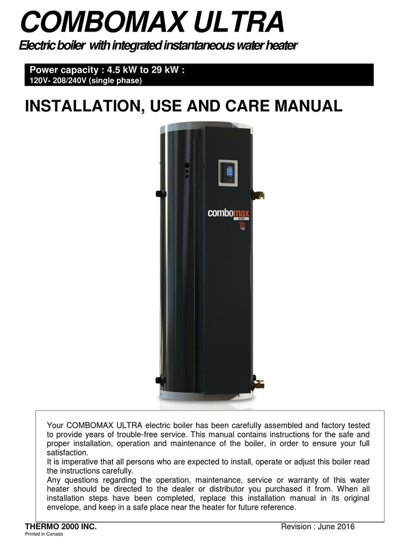
COMBOMAX ULTRA 12-4.5 Instruction and safety manual

COMBOMAX
TM
U l t r a
12
Electricboiler withintegratedinstantaneouswaterheater.
Power capacity 4.5 kW to 12 kW :
208/240 Volts ( single phase )
INSTALLATION, USE AND CARE MANUAL
Your COMBOMAX
®
electric boiler has been carefully assembled and factory tested to
provide years of trouble-free service. This manual contains instructions for the safe and
proper installation, operation and maintenance of the boiler, in order to ensure your full
satisfaction
It is imperative that all persons who are expected to install, operate or adjust this boiler read
the instructions carefully.
Any questions regarding the operation, maintenance, service or warranty of this water
heater should be directed to the dealer or distributor you purchased it from. When all
installation steps have been completed, replace this installation manual in its original
envelope, and keep in a safe place near the heater for future reference.
THERMO 2000 INC. rev. : September 2013
Printed in Canada

COMBOMAX™ Installation, use and care manual
(Revision Sept. 2013)
, Page
2.
Section 1 : Technical specifications
Table 1: Boiler specifications 240* Vac/1ph (3 wires L1/L2/N):
Suggested
electrical cable
Model Power Current
draw at 240V**
kW/Mbtu à
240v
Electric
heating
elements à 240v cu al
Fuse size
COMBOMAX ULTRA 12-4.5 4,5 / 15,3 1 x 4,5kW 19 12 10 25
COMBOMAX ULTRA 12-6 6 / 20.5 2x3kW 25 8 6 40
COMBOMAX ULTRA 12-7.5 7,5 / 25,6 1x4.5+1x3kW
31 8 6 40
COMBOMAX ULTRA 12-9 9 / 30,7 2x4,5kW 38 8 6 50
COMBOMAX ULTRA 12-12 12 / 41 2x6kW 50 6 6 70
*Can be also connected on an electrical supply at 208V/1ph giving 75% of the nominal capacity at 240V.
**Add amperage of the pump when required (5amp./1/6hp max). Local Electrical codes may require
different cable gauge according to the type of installation.
Maximum operating pressure on the tank: 207kPa / 30psi
Tank temperature range : 10
o
C to 90
o
C (50
o
F to 190
o
F)
Maximum pressure domestic water: 1033kpa (150psi)
Maximum domestic hot water temperature : 82
o
C (180
o
F)
Table 2 : Dimensions:
Height : 1537mm (60-1/2’’)
With : 559 mm (22’’)
Depth : 625 mm (25-1/2’’)
Plumbing connections :
oFresh water inlet : 3/4"NPT F
oDomestic hot water outlet : 3/4"NPT F
oExpansion tank : 1/2"NPT M
oHeating, supply : 1’’ NPT F
oHeating return : 1’’ NPT F

COMBOMAX™ Installation, use and care manual
(Revision Sept. 2013)
, Page
3.
General Safety Precautions
Be sure to read and understand the entire Manual before attempting to install or operate this
unit. Pay particular attention to the following General Safety Precautions. Failure to follow these
warnings could cause property damage, bodily injury or death. Should you have any problems
understanding the instructions in this manual, STOP, and get help from a qualified installer or
technician.
Section 2 : INTRODUCTION
The important safeguards and instructions
appearing in this manual are not meant to
cover all possible conditions and situations
that may occur. It should be understood that
common sense, caution and care are factors
which cannot be built into every product.
These factors must be supplied by the
person(s) caring for and operating the unit.
2.1 LOCAL INSTALLATION
REGULATIONS
This COMBOMAX™ Ultra 12 electric boiler must
be installed in accordance with these
instructions and must conform to local
regulation, or in the absence of local codes, with
the current edition of the National Plumbing
Code and the National Electric Code. In any
case where instructions in this manual differ
from local or national codes, the local or national
codes take precedence.
2.2 CORROSIVE ATMOSPHERE
The electric boiler should not be located near an
air supply containing halogenated hydrocarbons
or high humidity. The limited warranty is voided
when failure of the water heater is due to a
corrosive atmosphere.
2.3 SHIPMENT INSPECTION
Inspect the electric boiler for possible shipping
damage. The manufacturer’s responsibility
ceases upon delivery of goods to the carrier in
good condition. Consignee must file any claims
for damage, shortage in shipments, or non-
delivery immediately against carrier.
2.4 À VÉRIFIER
Please check the boiler identification plate to
ensure you have the right model.
The following items are factory installed
and shipped with the unit :
•207 kPa (30 psi) tank pressure
relief valve.
•862 kPa (125 psi) domestic hot
water pressure relief valve.
•Tank and domestic hot water heat
exchanger drain cocks.
•Thermo manometer (heat and
pressure indicator).
•Automatic air vent.
•83 kPa (12 psi) Tank pressure
regulator.
•Check valve with vacuum breaker.
•Thermostatic mixing valve on DHW
•Electric heating elements
•ULTRA SMART™ control.
Ezpansion tank is not included. This
component must be size according to the
heating system.
The COMBOMAX™ Ultra 12 electric boiler
should not be located in an area where
leakage from the tank or water connections
will result in damage to the adjacent area or
to lower floors of the structure. When such
areas cannot be avoided, a suitable drain pan
or non-flammable catch pan, adequately
drained, must be installed under the boiler.
The pan must be connected to a drain.
WARNING
!
WARNING
!
!

COMBOMAX™ Installation, use and care manual
(Revision Sept. 2013)
, Page
4.
Section 3 : INSTALLATION
The manufacturer’s warranty does not cover
any damage or defect caused by installation
or attachment or use of any special
attachment other than those authorized by
the manufacturer into, onto, or in
conjunction with the water heater. The use of
such unauthorized devices may shorten the
life of the water heater and may endanger life
and property. The manufacturer disclaims
any responsibility for such loss or injury
resulting from the use of such unauthorized
devices.
3.1 SAFETY MEASURES
All domestic and commercial installations will
include a pressure relief valve limiting the
operating pressure to 207 kPa (30 psi).
This COMBOMAX™Ultra 12 electric boiler is
designed for a maximum operating temperature
of 88°C (190°F). It is designed for hot water
heating system only. When allowed by local
regulation a 50% water and propylene-glycol
blend may be used on installation with fresh
water supply pressure above 240 kPa (35 psi). A
particular check valve avoiding back flow to
potable water may be required by local
authorities.
3.2 LOCATION
The COMBOMAX™Ultra 12 boiler should be
installed in a clean, dry location. Long hot water
lines should be insulated to conserve water and
energy. The boiler and piping should be
protected from exposure to freezing.
The COMBOMAX™Ultra 12 boiler must be
installed levelled and vertically. Adjustable legs
allow for levelling and stability.
The COMBOMAX™Ultra 12 boiler must be
located or protected so as not to be subject to
physical damage, for example, by moving
vehicles, area flooding, etc..
All models can be installed on combustible floors
and in alcoves. If the boiler is to be installed in a
restaurant or other location where the floor is
frequently cleaned, it must be elevated to
provide at least 150 mm (6”) clearance from the
floor as per NSF International recommendations.
The room temperature must be maintained
between 10C (50F) and 33°C (90°F).
3.3 CLEARANCE
The minimum clearances required for proper
inspection and servicing are as follows:
Table 4: Clearances Left side
0 mm / 0"
Right side
0 mm / 0"
Top
100 mm / 4"
Front
400mm / 16"
Back
0mm / 0"
WARNING
!

COMBOMAX™ Installation, use and care manual
(Revision Sept. 2013)
, Page
5.
Figure 1 : Top view, components identification and their location
Figure 2 : Front view, components identification and their location :

COMBOMAX™ Installation, use and care manual
(Revision Sept. 2013)
, Page
6.
Figure 3 : Basic installation diagram for a radiant floor heating system.
Figure 4 : Basic installation diagram for a radiator installation

COMBOMAX™ Installation, use and care manual
(Revision Sept. 2013)
, Page
7.
3.4 SYSTEM SETUP
Figures 1, 2, 3 and 4 indentifies and show
location of the different components. They also
provide typical heating system installation.
External components location may vary in order
to accommodate specific installation and local
codes and regulation.
3.5 HEATING WATER CIRCUIT
3.5.1 Connecting the heating water
piping
The boiler heating supply and return
connections are located on the left side (when
facing the unit) and are 1” NPT F.
Unions are recommended on the inlet and outlet
pipes to disconnect the water heater easily for
servicing if necessary.
Dielectric (insulating) unions should be used if
copper-steel connections are made.
Insulate all pipes containing hot water,
especially in unheated areas.
Never plug the pressure relief valve to avoid
creating a hazardous situation.
3.5.2 Flow-check valve
If the heating system uses a single or multiple
circulators without motorized zone valves, a
flow-check valve must be installed to
minimize gravity flow and heat loss during non-
draw periods. Modern circulators are typically
provided with spring loaded check valve that will
provide adequate protection.
If the heating system uses motorized zone
valves, these will provide adequate protection.
3.5.3 Pressure relief valve
The boiler is delivered with a factory installed
tank pressure relief valve set at 207 kPa (30
psi).
NEVER replace the pressure relief valve by a
higher set pressure one.
Connect the outlet of the relief valve downward
toward a safe location.
NEVER cap or plug a pressure relief valve
outlet. The pressure relief valve is a safety
apparatus and preventing its proper operation
may cause death, injury or property damage.
3.5.4 Operating pressure control &
expansion tank
The boiler is equipped with a factory installed,
pressure regulating make-up water equipped
with a flow check valve. This make-up water
allow filling of the boiler tank and the heating
system. It will also maintain a minimal operating
pressure cold pressure of 83 kPa (12 psi). When
operating the COMBOMAX™ Ultra 12 and the
heating system, pressure will vary between 83
kPa and 193 kPa (12 psi to 28 psi). The
operating pressure is affected by the type of
heating system and the size of the expansion
tank installed.
The expansion tank role is to compensate for
the heating system water expansion due to its
rise in temperature.
The expansion tank should have a minimum
capacity of 17,5l (4.6 usg). Lager expansion tank
could be required base on the heating system
size (wetted volume) or if the operating pressure
rise above 193 kPa (28 psi).
Expansion tank is generally wall or ceiling
mounted and is directly connected to the boiler
tank using the ½” NPT M connection provided.
3.5.5 Automatic Air Vent
The COMBOMAX™ Ultra 12 has a factory
installed tank automatic air vent. This air vent
function is to vent any air present in the tank.
For proper operation, do not cap or block the air
bleeder outlet.
For proper operation of the heating system, it
may be necessary to add air bleeders to the
heating system circuits.
3.5.6 Heating pump
A pump (or circulating pump) not included, is
required for the heating system to deliver
heating fluid (water) to the different heating
zone. Sizing of the pump is base on the heating
system configuration and is done by the installer
(heating technician, plumber, ).
3.5.7 Low temperature heating (Radiant
floor)
A thermostatic mixing valve or a similar device,
offering the same function, must be installed on
a heating system operating at less than 70°C
(160°F) like radiant floor system. The
thermostatic mixing valve limit the heating fluid
(water) supplied to the system at a preset
appropriated temperature, by mixing hot heating
fluid (water) supplied by the COMBOMAX™

COMBOMAX™ Installation, use and care manual
(Revision Sept. 2013)
, Page
8.
Ultra 12 to the relatively cold heating system
fluid (water) coming back from the radiant floor
(see figure 3).
3.6 DOMESTIC HOT WATER CIRCUIT
(Refer to figure 1 and 2 for component
identification and location).
3.6.1 Connecting the domestic hot water
piping
The COMBOMAX™ Ultra 12 boiler HOT
WATER OUTLET and the COLD WATER INLET
connections are clearly marked. They are
located on the right side (when facing the boiler)
and are of ¾” NPT F type.
Use only clean copper or approved plastic pipe
for water connections. Local codes or
regulations shall govern the exact type of
material to be used.
Insulate all pipes containing hot water,
especially in unheated areas.
A thermometer should be installed to indicate
the temperature of the water at or near the outlet
of the water heater.
3.6.2 Expansion tank on the cold water
supply line
Determine if a check valve, a back flow
preventer, a pressure-reducing valve, a water
meter or a water softener is present on the cold
water supply line.
Such items may create a closed system and
prevents the water as it is being heated from
expanding back into the cold water supply line.
Pressure can build up within the water heater,
causing the pressure relief valve to operate
during a heating cycle. This excessive operation
can cause premature failure of the relief valve
and possibly of the water heater itself.
Replacing the relief valve will not correct the
problem. One method of preventing pressure
build-up is to install an expansion tank on the
cold water supply line between the
COMBOMAX™ Ultra 12 boiler unit and check
valve. Contact your installing contractor, water
supplier, local plumbing inspector or plumbing
supply house for assistance.
3.6.3 Domestic hot water pressure relief
valve
The COMBOMAX™ Ultra 12 boiler boiler is
factory equipped with a pressure relief valve
installed on the domestic hot water boiler outlet.
This pressure relief valve is set at 862 kPa (125
psi). Connect both the domestic hot water ( 862
kPa / 125 psi) and the tank heating system (207
kPa / 30 psi) pressure relief valves downward
toward safe location.
Relief valve outlet pipe diameter must not be of
smaller diameter than the relief valve outlet. The
oulet pipe end must be visible in order to
observe any relief incident and be protected
from freezing.
3.6.4 Thermostatically controlled mixing
valve (included)
The COMBOMAX™ Ultra 12 boiler boiler is
factory equipped with a thermostatically
controlled mixing valve that reduce the risk of
scald injury by lowering the domestic hot water
temperature at the heat exchanger outlet, by
mixing cold fresh water to the hot water coming
out of the heat exchanger.
In order to adjust the mixing valve, hot water
must be consumed.
3.7 BOILER WIRING
3.7.1 Main power supply
The electrical wiring and grounding must
conform to local codes or, in their absence, to
the National Electrical Code. Local codes have
authority for wiring and electric breaker sizing. It
is the electrical technician responsibility to insure
that the installation meets the applicable codes
requirements.
On installation where a 120 Vac power is
required for a heating pump and other outboard
components, main power supply to the
COMBOMAX™ Ultra 12 must be a 120/240 Vac,
single phase, 60 Hz using 3 conductors (L1 –
L2 – N) and a ground wire..
On installation where no 120volts components
such a pump need to be powered by the
Combomax, Power supply could then be
supplied with only two conductors L1 L2 with a
ground wire.
Electrical current draw for the boiler being
installed is indicated on the boiler’s name plate.
The electrical technician needs this information
in order to determine the proper electrical

COMBOMAX™ Installation, use and care manual
(Revision Sept. 2013)
, Page
9.
breaker and cable . The cable can be either
aluminum or copper, but must be adequate for
90°C (195°F) operation.
3.7.2 Heating pump wiring
If the building heating system is designed for a
single pump operation and the electrical power
to the boiler is 120/240 Vac 3 conductors plus
ground type, the pump (1/6 HP max) can be
directly connected to the boiler electric panel
“PP” terminals. The boiler control will operate
the pump as soon as a heat demand is signalled
by the space thermostat. The control would shut
the circulating pump off if the tank water
temperature is below the minimal set point,
giving priority to the domestic hot water over
building heat.
If the building heating system is made of multiple
circulating pump and if the domestic hot water
prioritisation function is kept, the boiler electrical
panel “PP” terminals can be used as a dry
contact ( 5 amps or 1/6 hp) to operate a relay,
shutting power to the pumps when domestic hot
water priority is needed.
3.7.3 Room thermostat wiring
3.7.3.1 Single heating zone
Using a two (2) leads thermostat, connect the
low-voltage thermostat dry contact to the Wand
Rterminals on the COMBOMAX™ Ultra 12
electrical panel (DO NOT apply current to
these terminals).
Using a three (3) leads thermostat, connect the
C, W and R terminals to the boiler electric panel
corresponding terminals.
3.7.3.2 Zone valve zoning
Connect the low-voltage thermostat to the zone
valve. The components must wired such that,
upon a heating demand from a thermostat, only
the corresponding zone valve will be actuated
and will in turn activate the COMBOMAX™ Ultra
12 . Connect the zone valve dry end switch
contact to the W and R boiler electrical panel
terminals.
.
The 24 Vac power supply transformer used must
be powerful enough to supply simultaneously all
zone valves.

COMBOMAX™ Installation, use and care manual
(Revision Sept. 2013)
, Page
10.
EL1
L2 G
Diagramme électrique/ Wiring diagram
COMBOMAX ULTRA 12- .5kW
N
F
L1
R1
12 C
11
10
9 Com
8 Boil in
7 Boil O
6 Sup/D
5 Os
4 Com
3 S t D
2 Ht D
1 CD
24 R
23 Alarm
22 Stg 4
21 Stg 4
20 Stg 3
19 Stg 3
18 Stg 2
17 Stg 2
16 Stg 1
15 Stg 1
14 Pmp
13 Pmp W
R
P
P
R1
40VA
G
HL
C1
240V 24Vac
Pomp /
Pump
120V x 1/6HP max
D mand Chauffag th rmostat/
H at D mand th rmostat
Lég nd / L g nd
TH
C
R
HL
Aquastat
R lais
R lay
Haut limit
Hi-Limit
Fusibl
Fus
Disjonct ur
Brak r
Cablag n usin /
Factory wiring
Cablag par l'installat ur/
Wiring by oth rs
Élém nt chauffant/
H ating l m nt
Contact ur
Pow r r lay
C1-1
Contrôleur/Control
ULTRA SMART
Aux.
Bi-E
R
Outdr s ns
Boil r out
C1-2
Blanc/whit
Bl u
Bl u
Bl u
Bl u
Roug /R d
Roug /R d
Noir/blk
Noir/blk
Bl u
Sond t mp. chaudièr /
Boil r t mp. S nsor
Roug /R d
Boil r in
C
R
W
C
Roug /R d
Cablag n usin
facultatif/
Optional factory wiring

COMBOMAX™ Installation, use and care manual
(Revision Sept. 2013)
, Page
11.

COMBOMAX™ Installation, use and care manual
(Revision Sept. 2013)
, Page
12.
Section 4 : (
Ultra Smart
™) CONTROL SET UP
4.1 INTRODUCTION
The COMBOMAX™ Ultra 12 boiler is designed to be
used in hydronic heating application where the
heating fluid (water) pass through the boiler before
being supplied to the heating system (parallel
system). It is also design to provide domestic hot
water needs to the building.
The COMBOMAX™ Ultra 12, ULTRA SMART™
control main function is to maintain the boiler water
temperature between preset values by operating the
heating element(s). It is also capable of directly
managing one heating system circulating pump.
4.2 LIQUID CRYSTAL DISPLAY (LCD)
NFORMATION
The Ultra Smart™ control LCD shows operating
functions and values and allows you to adjust them

COMBOMAX™ Installation, use and care manual
(Revision Sept. 2013)
, Page
13.
4.3 INTERFACE OPERATION
The Ultra Smart™ control access is through four (4)
keys.
Key provides access to the configuration
menu and is also used as an « ENTER key » to
confirm the selection. The two rocking (2) keys
allow items selection or value
change.
The key light-up the LCD back screen. The
screen will remain lighted until the key is
depressed again. Depressing any other keys will
light-up the LCD for a default value of 10 sec.
Depressing the key will turn the LCD lighting
OFF.
4.4 COMBOMAX MODE OPERATION
The Ultra Smart™ control manages both the heating
element(s) and circulation pump. It tries to maintain
the boiler tank temperature around the target
temperature shown on the display. When the tank
temperature decrease under the target temperature,
the heating element(s) is turned ON and modulate
trying to maintain the target temperature. On units
equipped with two (2) heating elements, the heating
elements will be used in sequence in order to insure
equal aging.Heating stages are indicated on the
LCD by the darkening of the icon.
On an heat demand, the control will turn the
circulating pump ON if the tank water temperature is
high enough to satisfy the domestic hot water
demands. The following symbol will appear on the
upper right of the display. (see next section
on domestic hot water prioritisation). The controller
will stop the circulating pump once the space heat
demand is satisfied or if the boiler temperature drops
too much (see section 4.5)
4.5 DOMESTIC HOT WATER DEMAND
PRIORITISATION.
The Ultra Smart™ control can manage both heat
and domestic hot water demand. It’s program
prioritize domestic hot water production over building
heating in case of low tank water temperature. The
control accomplished this operation by turning the
heating circuit circulation pump OFF until the tank
water temperature return to normal.
The value of the tank temperature decrease under
the established target temperature shown on the
display is adjustable on the configuration menu of
the control.
This function has minimal impact on the building
temperature since typically domestic hot water
demands are of short enough duration that the
building temperature will not be affected.
4.6 CONTROL SET-UP
Since every application presents different heating
and domestic hot water needs, it is important to
properly set-up the COMBOMAX™ Ultra 12 for the
application in order to maximise its performances.
In order to set-up the COMBOMAX™ Ultra 12
control, the installation technician has to access the
Ultra Smart™ control configuration menu in pressing
on the for 2 sec. until the first menu is
displayed.
Selecting the function or the value to adjust is by
using the rocking keys .
Pressing the key confirm your selection an
brings you to the next menu.
Table 1 below shows the menus that will appear.
If keys are not depressed for more than 15 sec. the
controller will register the last changes and returns
to normal operation display. Scrolling to the end of
the menus will also return the LCD to normal
operation display.
In case of power failure, function set-up are saved
and restored with when electrical power is returned.

COMBOMAX™ Installation, use and care manual
(Revision Sept. 2013)
, Page
14.
Table 1
ITEM DESCRIPTION CHOICE DEFAULT
Select user preferred units. F
0
or C
0
F
0
If required, change the preset target temperature of
the controller to the value required to adequately
heat the building and supply all the domestic hot
water needs of the user. Tank water temperature
target set point. temperature is factory set at 80°C
(175°F). Increasing the tank water temperature will
increase the amount of energy available for
supplying heating and domestic hot water demand.
65C° to 88°C
(150°F to 190°F)
80°C
(175°F)
Select the tank temperature drop required to stop
the space heating pump during space heating
demands. Once the tank temperature will have
dropped by the selected value, the circulating pump
will be turn OFF momentarily until the tank water
temperature is return to normal.
0FF, 3°C to 20°C
(5°F to 40°F)
differential
5°C
(10°F)
NOTE : Once operating values have been set, the controller will save them and return to normal operation
display. The user can change the tank water temperature set point without accessing the configuration
menu (see section 4.7)
4.7 USER ADJUSTED TANK
TEMPERATURE SET POINT.
The tank temperature set point can be adjusted
without accessing the configuration menu or
changing the installer original set-up.
By using the rocking keys .
Depressing one of the keys will cause a flashing
“0” to be displayed. This zero indicates that the
“user” differential value is zero. By using the
“+” or “-“ keys, the user can
input a temperature differential between the
installer set point and the actual operation set
point. The maximum user differential is ± 5°C
(10°F).
The new user differential value will be display,
flashing for 5 sec. before the LCD return to
normal operation display.
Once completed, the new user differential value
will be display in a flashing mode every time the
rocking keys are depressed.

COMBOMAX™ Installation, use and care manual
(Revision Sept. 2013)
, Page
15.
Section 5 : OPERATION
5.1 SAFETY PRECAUTIONS
Before operating the
COMBOMAX Ultra 12
boiler, be sure to read and follow these instructions,
as well as the warnings printed in this manual. Failure to do so can result in unsafe operation of the
water heater resulting in property damage, bodily injury, or death. Should you have any problems
reading, following or difficulty in understanding the instructions in this manual, STOP, and get help
from a qualified person.
To meet building heating and domestic hot water
needs, the controller on this boiler is adjustable
up to 88°C (190°F) and regulate the temperature
of tank. However, domestic hot water is not
controlled by this controller but by the
thermostatic mixing valve located in the upper
section of the unit (see fig.1). Domestic hot
water temperatures over 52°C (125°F) can
cause severe burns instantly or death from
scalds. 50°C (120°F) is the recommended
starting point for setting the control to supply
general-purpose hot water.
Safety and energy conservation are factors to be
considered when setting the operating
temperature of the tank and domestic hot water.
The most energy efficient operation will result
when the temperature setting is the lowest that
satisfies both requirements.
The following chart details the relationship of
water temperature and time with regard to scald
injury and may be used as a guide in
determining the safest water temperature for
your applications
TIME TO SCALDING VS TEMPERATURE
RELATIONSHIP
Temperature Time to scalding
50°C (120°F) Over 5 minutes
52°C (125°F) 1-1/2 to 2 minutes
54°C (130°F) About 30 seconds
57°C (135°F) About 10 seconds
60°C (140°F) Less than 5 seconds
63°C (145°F) Less than 3 seconds
66°C (150°F) About 1-1/2 second
68°C (155°F) About 1 second
With kind permission from the Shriners Burn Institute
The thermostatic controlled mixing valve should
be adjusted by opening a domestic hot water tap,
measuring the water temperature with a
thermometer and by adjusting the thermostatically
control mixing valve accordingly.
There is a hot water scald potential if the
thermostatically controlled mixing valve for
reducing point-of-use water temperature is
damaged, not properly working removed or
by-passed.
DANGER
!
!

COMBOMAX™ Installation, use and care manual
(Revision Sept. 2013)
, Page
16.
5.2 FILLING THE WATER HEATER TANK
Do not turn ON the boiler unless it is filled
with water. Do not turn ON the boiler if cold
water supply shut-off valve is closed.
Make sure the drain valve of the tank is closed.
Open the cold water valve supplying the boiler.
Bleed the air from the tank by opening the
pressure relief valve located on top the water
heater tank while you are filling the tank.
Once the reservoir is filled, close the pressure
relief valve. Tank pressure should stabilise at a
value of approximately 83kPa (12psi).
Open the boiler service valve to the heating
system. (If the heating system use motorized
zone valves, these valves must be manually
open. With the motorized valve open, start the
circulating pump, check for leaks and repair as
required.
Bleeds air from the tank and from the heating
zone(s).
5.3 FILLING THE DOMESTIC WATER
HEATER HEAT EXCHAGER
There is a heat exchanger located in the water
heater tank that separate the thermal mass fluid
(water) and the domestic hot water. This heat
exchanger containing potable water must be
filled.
Make sure that the heat exchanger drain cock is
turn off.
Open the nearest domestic hot water tap as well
as any control valve on the water heater outlet
(the copper tube at the top of the water heater).
The cold water supply to the boiler shall be
Open.
Close the domestic hot water tap as soon as
water flows out of it. Fix any leaks
One must open every hot water domestic hot
water tap in succession, in order to evacuate air
from the distribution system.
5.4 BOILER CONTROLLER SETTING
Safety and energy conservation are factors to be
considered when setting the water temperature
on the controller. The most energy efficient
operation will result when the temperature
setting is the lowest that satisfies all
requirements.
However, a tank water temperature of 70°C
(160°F) as a starting point , is recommended
to insure a good supply of domestic hot
water.
It may be necessary to rise the tank water
temperature up to 88°C (190°F) in order to
supply to the domestic hot water demand or
when the unit is installed on space heating
systems requiring higher operating temperature.
Adjust tank water temperature differential to
allow priority on domestic hot water supply. A
value ranging from 5°C to 10°C (10°F to 20°F) is
generally adequate.
5.5 START UP PROCEDURE
1. Fill tank and heat exchanger as
described in sections 5.2 and 5.3.
2. Adjust temperature levels as described
in section 5.4
3. Adjust building room thermostat(s)
above ambient temperature.
4. Turn ON the boiler main electric supply
breaker.
5. The boiler main contactor should close
with an audible snap sound, and all
elements should turn on in sequence.
6. Tank temperature should gradually
increase. Several hours may be
required according to the power
capacity of the Combomax and the type
of heating system to reach the tank
water temperature target.
7. The circulating pump(s) will start once
the tank water temperature will reach
the tank water target temperature minus
the programmed pump differential
temperature.
8. If the heating system is of the radiant
floor or low temperature type, adjust the
heating system mixing valve to the
proper temperature.
9 Lower the setting of the room
thermostat, the heating pump should
stop but not the heating elements which
will stop only when the boiler
temperature will reach the target
temperature.
WARNING
!

COMBOMAX™ Installation, use and care manual
(Revision Sept. 2013)
, Page
17.
9. As the tank water temperature reaches
its target temperature, the heating
elements will be turned off in
succession.
5.6 THERMOSTATICALLY CONTROLLED
MIXING VALVE SETTING
A thermostatically controlled mixing valve
automatically regulates the mix of very hot and
cold water as required, providing safe domestic
hot water under variable conditions.
To adjust the mixing valve setting, carefully open
a hot water tap. Protect yourself against the
scalding. Measure the hot water temperature
with a thermometer. Mixing valve adjustment is
achieved by turning the mixing valve knob
clockwise to reduce the domestic water
temperature, contraclockwise to raise the
domestic water temperature
Unless local regulation requires otherwise, a
50°C (120°F) is considered the best temperature
to reduce heat loss through the plumbing and
prevent scalding for young kid and senior
citizen. Generally residential dishwasher are
provided with their own water heating element
and don’t required hotter water.
Raising the domestic hot water outlet
temperature will not provide more domestic hot
water. In order to provide more domestic hot
water, the amount of energy in the water heater
tank need to be increase, this is achieved by
increasing the water tank temperature
(maximum 88°C /190°).

Chaudière électrique COMBOMAX
MC
Guide d’installation, d’utilisation et d’entretien
(Révision Sept.2013)
, Page
18.
Section 6 : MAINTENANCE
6.1
INTRODUCTION
Regular water heater maintenance will ensure
trouble-free service for many years. It is
recommended that you set up and follow a
maintenance program. All component may fail
eventually. The use of incorrect replacement
parts or disregarding safety procedures and
warnings during repairs may reduce the boiler
safety level and shorten its useful life.
The owner should set up the following
maintenance program.
6.2 AT ALL TIMES
The boiler should be immediately inspected in
case of:
Overheating or burn plastic odours are
detected.
Water leak from the boiler or the space
heating system is found.
If the hot water is leaking from the boiler pressure
relief valve, it may indicate a problem with some
components of the space heating system..
Immediate attention and repair by a qualified
technician are required. NEVER CLOSE OR
PLUG A PRESSURE RELIEF VALVE.
6.3 EVERY 6 MONTHS
Check automatic air vent proper
operation.
Using hand operated air vent installed on
the heating system radiators or in other location,
bleeds air from the heating system.
6.4 YEARLY INSPECTION
___________________________________
Make sure that the power supply to the water
heater has been turn off at the circuit breaker
before attempting any work on the water
heater.
Visual inspection of the water heater
electrical cabinet. Checks for leaks at the heating
elements, sign of overheating of electrical
components and wiring.. At the beginning of the
heating season, Check for proper operation of
the boiler controller, circulating pump(s), mixing
valve for low temperature heating system, room
thermostat(s) and other heating system
components for proper operation.
Check the domestic hot water
thermostatic mixing valve proper operation by
measuring domestic water temperature at a
domestic hot water tap with a thermometer.
Check for proper operation of the
automatic air vent, located on top of the water
heater, by removing its cap and by pressing on
the knob, releasing air until water began to be
expelled.
Do not open the tank drain tap unless
repair to the water heater is required. Opening
the drain tap will eventually force fresh water into
the tank. This water introduce oxygen diluted in
the fresh water. This oxygen will cause corrosion
of the tank internal surfaces, damaged the
reservoir and void the warranty.
If repair is required, it should be
accomplish as soon as possible, by a qualified
technician and using genuine replacement parts.
_______________________________________
The manufacturer’s warranty DOES NOT
cover problems caused by improper
installation or maintenance. If the safety valve
opens periodically, it may be due to the
expansion tank. Immediately call a qualified
technician to appraise and repair the problem.
WARNING
DANGER
!

Chaudière électrique COMBOMAX
MC
Guide d’installation, d’utilisation et d’entretien
(Révision Sept.2013)
, Page
19.
COMBOMAX
TM
Ultra 12 LIMITED WARRANTY
Warranty Coverage for Residential Installation.
Thermo 2000 Inc. hereby warrants to the original residential purchaser that the
COMBOMAX Ultra 12 tank and exchanger installed in a residential setting shall
be free of leaks during normal use and service for a period of fifteen (15) years from
the date of purchase as long as the original residential purchaser owns the home in
which the unit was originally installed. Residential setting shall mean usage in a
single-family dwelling in which the consumer resides on a permanent basis. Also,
residential setting shall mean use in multiple family dwellings in which one (1)
COMBOMAX Ultra 12 tank and exchanger is to be use in only one (1) dwelling.
In the event that a leak should develop and occur within this limited warranty period
due to defective material or workmanship, such leak having been verified by an
authorized company representative, Thermo 2000 inc. will repair or replace at our
sole option the failed unit with the nearest comparable model at the time of
replacement.
The original residential purchaser is responsible for all costs associated with the
removal and reinstallation, shipping and handling to and from manufacturing plant.
The replacement unit will be warranted for the remaining portion of the original
Warranty.
Warranty Coverage for Commercial Installation.
Thermo 2000 Inc. hereby warrants to the original residential purchaser that the
COMBOMAX Ultra 12 tank and exchanger (coil assembly) installed in a
commercial setting shall be free of leaks during normal use and service for a period
of ten (10) years from the date of purchase. Commercial setting shall mean use in
other than residential setting stated above in the residential setting definition. In the
event that a leak should develop and occur within this limited warranty period due to
defective material or workmanship, such leak having been verified by an authorized
company representative, Thermo 2000 inc. will repair or replace at our sole option
the failed unit with the nearest comparable model at the time of replacement.
The original purchaser is responsible for all costs associated with the removal and
reinstallation, shipping and handling to and from Manufacturer. The replacement
unit will be warranted for the remaining portion of the original Warranty.
Limited two years warranty on all COMBOMAX
™
Ultra 12
components & parts
All other COMBOMAX Ultra 12 components & parts are warranted for a period of
two (2) years against defects due to defective material or workmanship. The
original purchaser is responsible for all costs associated with the removal and
reinstallation, shipping and handling to and from Manufacturer. The components,
repaired or replaced are warranted for the residual period of the initial warranty on
the unit.
Exclusions
This warranty is void and shall not apply if:
A) Defects or malfunctions resulting from installation, repair, maintenance
and/or usage that are not done in conformity with the manufacturer’s
installation manual; or
B) Defects or malfunctions resulting from installation, maintenance, or
repair that are not done in accordance with regulations in force; or
C) Defects or malfunctions resulting from improper installation,
maintenance or repair done carelessly or resulting from consumer
damage (improper maintenance, misuse, abuse, accident or alteration);
or
D) Installation in which a relief valve (pressure) is not installed or if it is not
functioning properly, or when it is not connected to a drain to avoid
damage to the property; or
E) Installation in which liquid circulating in the tank does not remain in
closed circuit or installation in which piping is leaking; or
F) A polybutylene pipe or radiant panel installation without an oxygen
absorption barrier is used; or
G) Installation where the acidity of water is not within the normal Environmental
Protection Agency (EPA) (between pH 6.5 – 8.5) guidelines or the domestic
water contains abnormal levels of particulate matter or water exceeding 10.5
gpg; or
H) Your home contains any type of water softener system and the unit is not
installed and maintained in accordance with the manufacturer specifications;
or
I) When installed with a low pressure steam boiler, if sludge is allowed to
accumulate in the COMBOMAX tank and boiler water acidity is lower than pH
6.5 or higher than pH 8.5; or
J) The COMBOMAX unit is being subject to non authorized modifications; or
K) Defects or malfunction resulting of storing or handling done elsewhere than
Thermo 2000’s manufacturing plant; or
L) Units on which the serial number is removed or obliterated.
Limitations.
Thermo 2000 shall not be responsible for any damage, loss, and inconvenience of any
nature whatsoever, directly or indirectly, relating to the breakdown or malfunction of the
unit. This warranty limits its beneficiary’s rights. Nevertheless, the beneficiary may have
other rights, which vary from state to state.
This warranty replaces any other expressed or implicit warranty and constitutes the sole
obligation of Thermo 2000 towards the consumer. The warranty does not cover cost of
removal, reinstallation or shipping to repair or replace the unit, nor administration fees
incurred by the original consumer purchaser.
Thermo 2000 reserves its rights to make changes in the details of design, construction, or
material, as shall in its judgment constitute an improvement of former practices.
This warranty is valid only for installations made within the territorial limits of Canada and
the United States.
Warranty service pr cedure
Only authorized COMBOMAX Ultra 12 dealers are permitted to perform warranty
obligations. The owner or its contractor must provide Thermo 2000’s head office or
authorized depot with defect unit together with the following information: COMBOMAX
model and serial number, copy of the original sales receipt and owner’s identification
certificate.
This manual suits for next models
4
Table of contents
Other COMBOMAX Boiler manuals
Popular Boiler manuals by other brands

THERMOSTAHL
THERMOSTAHL ENP 20 Installation and service manual

Daikin
Daikin EKHWET90B V3 Series installation manual

Alternate Heating
Alternate Heating wood gun E100 SF Installation and operator's guide

Keston
Keston K260 User instructions

Viessmann
Viessmann Vitodens 222-F installation instructions

Weil-McLain
Weil-McLain WMB-155C manual

STIEBEL ELTRON
STIEBEL ELTRON MAZ manual

Precision
Precision HWST Installation and operating instructions

Cecilware
Cecilware ME10E-N Operation manual

Orlanski
Orlanski ORLIGNO 200 Instruction manual & service manual

Lochinvar
Lochinvar Knight XL 400 User's information manual

Metal-Fach
Metal-Fach SE MAX II Technical And Operating Manual