Comet XRC-3023-WA User manual

Industrial X-Ray
Cooler Manual XRC-3023-WA
3000 Watt Water to Air Cooler

2
COMET AG
Herrengasse 10
3175 Flamatt
Switzerland
Phone: +41 31 744 9000
Fax: +41 31 744 9090
Internet: www.comet-xray.com
Protection Notice
Dissemination as well as copying of this document, utilization or posting of its contents is not permitted
unless formally granted. Violations entail claims for compensation. All copyrights, including rights due
to patent grant or registration of a utility model or design, are reserved.
All product names used in this manual are trademarks of the corresponding manufacturers.
Technical modifications are subject to change.

3
Contents
1. ABOUT THIS MANUAL ...............................................................................6
1.1. Explanation of symbols and signs .............................................................6
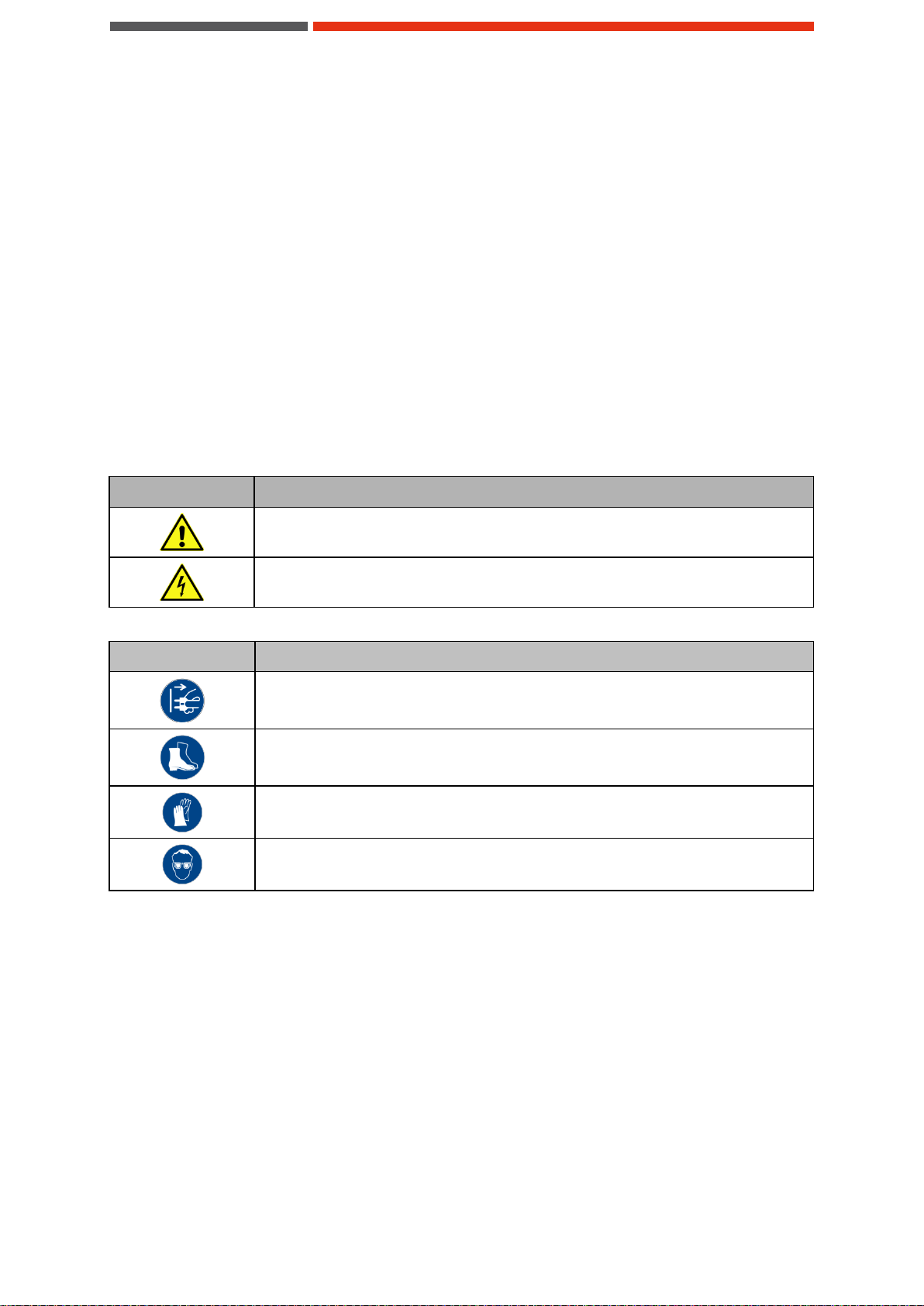
1.1.1. Safety symbols .......................................................................................................................................6
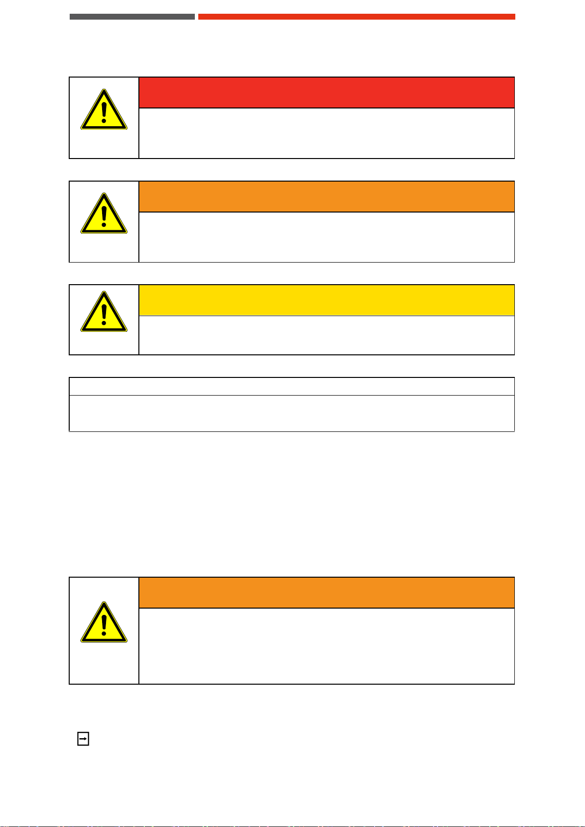
1.1.2. Warning instructions...............................................................................................................................6
1.1.3. Text designations....................................................................................................................................8
1.2. Illustrations...................................................................................................8
1.3. Terms of warranty........................................................................................8
1.4. Contact information.....................................................................................9
2. SAFETY......................................................................................................10
2.1. Hints for the safe operation.......................................................................10
2.1.1. Prevent hazards....................................................................................................................................10
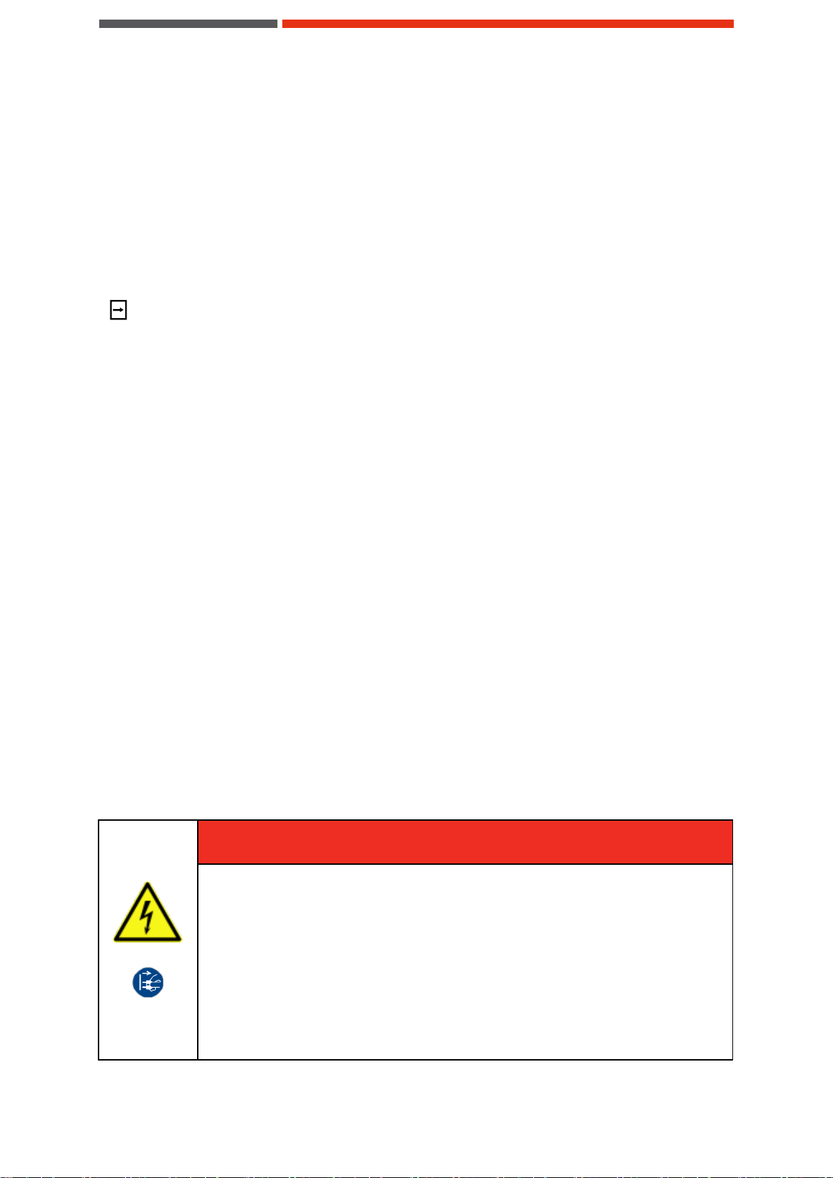
2.1.2. Hints regarding the electrical equipment...............................................................................................10
2.1.3. Inadmissible operating conditions.........................................................................................................11
2.2. Responsibilities of the unit operator........................................................12
2.2.1. Planning and monitoring the safety measures......................................................................................12
2.2.2. Minimizing the risk of injury...................................................................................................................12
2.3. Personnel requirements............................................................................12
2.3.1. Qualifications........................................................................................................................................12
2.3.2. User groups..........................................................................................................................................13
2.3.3. Specialized knowledge.........................................................................................................................13
2.3.4. Exclusion criteria...................................................................................................................................14
2.4. Personal protective gear ...........................................................................14
2.5. Safety and signaling equipment included in the unit..............................14
2.6. Guards.........................................................................................................15
2.7. Caution label...............................................................................................15
2.8. In case of accidents...................................................................................15
2.9. Environmental issues................................................................................15
3. PRODUCT IDENTIFICATION ....................................................................16
3.1. Unit specifications .....................................................................................16
3.2. Identification plate .....................................................................................16
4. UNIT DESCRIPTION..................................................................................17
4.1. Intended use...............................................................................................17
4.2. Non-conformity with the intended use.....................................................17

4
4.3. Predictable errors during operation.........................................................17
4.4. Unit components........................................................................................18
4.4.1. Cooling circuit.......................................................................................................................................18
4.5. Technical specifications............................................................................18
5. TRANSPORT, PACKING AND STORAGE ...............................................20
5.1. Safety ..........................................................................................................20
5.2. Checking the delivery condition...............................................................20
5.3. Symbols on the packaging........................................................................21
5.4. Packing .......................................................................................................21
5.5. Manual handling.........................................................................................22
5.6. Handling with industrial truck...................................................................22
5.7. Storing the unit...........................................................................................22
5.8. Preparing the unit for the further transport .............................................23
6. INSTALLATION AND COMMISSIONING..................................................24
6.1. Requirements concerning the installation location................................24
6.1.1. Installation location...............................................................................................................................24
6.1.2. Environmental conditions......................................................................................................................24
6.1.3. Infrastructure ........................................................................................................................................24
6.1.4. Placing the unit.....................................................................................................................................24
6.2. Using the unit for the first time.................................................................25
6.3. Connecting the unit electrically................................................................25
6.4. Putting the unit into operation..................................................................26
7. CONTROLLING THE UNIT........................................................................27
7.1. Switching on the unit.................................................................................27
7.2. Switching off the unit.................................................................................27
7.3. Settings.......................................................................................................27
7.3.1. Flow switch...........................................................................................................................................27
7.3.2. Pressure relief valve.............................................................................................................................28
7.3.3. Thermostat ...........................................................................................................................................29
8. DISRUPTIONS ...........................................................................................30
8.1. Safety ..........................................................................................................30
8.2. Disruption in operation..............................................................................30
8.2.1. Troubleshooting....................................................................................................................................30

5
9. MAINTENANCE AND CLEANING.............................................................32
9.1. Safety ..........................................................................................................32
9.2. Maintenance schedule...............................................................................34
9.3. Preparing the unit for maintenance..........................................................35
9.4. Disconnecting the coolant hoses.............................................................35
9.5. Connecting the coolant hoses..................................................................36
9.6. Draining the coolant ..................................................................................37
9.7. Adding coolant...........................................................................................38
9.8. Removing and mounting the unit cover...................................................38
9.9. Removing and mounting the cover for electrical connections..............39
9.10.Cleaning the filter strainer.........................................................................40
9.11.Cleaning the heat exchanger ....................................................................41
9.12.Cleaning the casing ...................................................................................42
10. REPAIR...................................................................................................43
10.1.Safety ..........................................................................................................43
10.2.Repair procedures .....................................................................................43
11. DECOMMISSIONING AND DISPOSAL.................................................44
11.1.Temporary placing out of operation.........................................................44
11.2.Returning the unit to service after decommissioning.............................44
11.3.Final decommissioning, disposal.............................................................45
11.4.Disposal of operating materials................................................................45
11.5.Return of the unit to COMET.....................................................................45
12. WEAR PARTS AND SPARE PARTS.....................................................46
13. ADDENDUM............................................................................................47
13.1.Performance diagram ................................................................................47
13.2.Flow chart...................................................................................................48
13.3.Wiring diagram...........................................................................................49
13.4.Dimension drawing....................................................................................51

6
1. About this manual
This document is the manual for the cooling unit XRC-3023-WA. It is based on international safety
regulations.
This operating manual addresses the needs of the user of the unit. Its intention is to allow the safe
operation of the unit. Thus, it should be read carefully and be kept accessible for the users of the unit
at any time.
All chapters of this operating manual can be read independently and thus can be used for look-up
purposes.
1.1. Explanation of symbols and signs
1.1.1.Safety symbols
The safety symbols used in this operating manual are indicated below. The main reason for their use
is to point the reader to the safety instruction given in the text field beside.
Symbol
Meaning
Warning with respect to general danger or damage to property.
Warning with respect to electrical hazard.
Table 1: Warning signs
Symbol
Meaning
This symbol indicates the requirement of disconnecting from mains.
This symbol indicates the requirement of wearing protective footwear.
This symbol indicates the requirement of wearing protective gloves.
This symbol indicates the requirement of wearing protective eyewear.
Table 2: Mandatory action signs
1.1.2.Warning instructions
In this operating manual concrete warning instructions are given in order to point out unavoidable re-
sidual risks when operating the unit. These risks include hazard for
Human beings
The unit and other equipment
The environment
Warning instructions in this operating manual are identified using symbols. The warning instructions
are introduced using signal words which express the scale of the hazard.
Always comply with the warning instructions and act cautiously in order to avoid accidents, injuries to
persons and damage to property.

7
DANGER
DANGER
Reference to immediate danger to human health.
Failure to comply with this warning instruction will result in severe irreparable injury
and even death.
WARNING
WARNING
Reference to recognizable hazard to human health.
Failure to comply with this warning instruction may result in severe irreparable injury
and even death.
CAUTION
CAUTION
Reference to recognizable hazard to human health.
Failure to comply with this warning instruction may result in slight to medium injury.
NOTE
Reference to a material hazard.
Failure to comply with this warning instruction may result in material damage.
Structure of the warning instructions
The following information builds the warning instructions:
Warning symbol
Signal word
Type and source of the hazard
Causing
Measure(s) to avoid the hazard
Example:
WARNING
WARNING
Risk of burning and/or scalding due to possibly hot coolant.
Coolant can reach high temperatures during operation and cause burns or scalding
in the case of contact.
Check whether the coolant is hot before handling it. If necessary, let it cool down to
the ambient temperature, that there is no more risk of burns or scalding.
Important information and tips concerning operation of the unit
This symbol is used to highlight passages with important information and tips concerning operation of
the unit.

8
1.1.3.Text designations
Text mark-ups
Text that appears in bold refers to emphases and subheadings.
Step-by-step instructions
Step-by-step instructions have the following structure:
Objective for action
Requirement(s)
Tools and material required
Procedure
Prompt to take action (indicated by a 1)
Prompt to take action (indicated by a 2)
(Preliminary) result
Prompt to take action (indicated by a 3)
Prompt to take action (indicated by a n)
Result
1.2. Illustrations
Illustrations in this operating manual are provided for general understanding and can be different from
the actual version of the unit.
1.3. Terms of warranty
General sale and delivery terms of COMET apply. The buyer accepts these terms, at the latest when
signing the contract of purchase.
The particular terms of warranty and duration of warranty of the unit in question can be taken from the
contract documents as well as from the order confirmation.
Warranty claims and liability are excluded in case of one of the following situations:
Use of the unit in an unintended way
Inaccurate installation, putting into service, operation, repair or maintenance of the unit by
people that are not fully authorized
Use of the unit despite of defect, wrongly implemented or non-functional safety devices or
protective gear
Unauthorized or forbidden modifications by the user concerning the electrical equipment
of the unit
Unauthorized or forbidden modifications by the user concerning the mechanical structure
of the unit
Unauthorized or forbidden modifications by the user concerning the operating parameters
Use of unauthorized tools
Use of unauthorized operating supplies
Exceedance of mandatory maintenance intervals
Cases of disaster caused by foreign matter influence or act of nature beyond control

9
NOTE
Any form of unintended use of the unit and any structural change caused by the user without prior
authorization in written form by COMET will lead to the termination of warranty as well the termina-
tion of the declaration of conformation and will free COMET from product liability. This concern in-
cludes safety devices as well.
In case of authorized changes or when adding optional equipment it is the sole responsibility of the
customer to assure the accurate implementation of the safety devices required.
1.4. Contact information
If you have questions with respect to this unit please use the contact information given below. Always
communicate the following:
Your name and address
Name of contact at your address
Product data as on identification plate: Type of unit, serial number, article number and
year of manufacture
Company contact:
Mail:
COMET AG
Herrengasse 10
CH-3175 Flamatt
Internet:
http://www.comet-xray.com
E-Mail:
Phone:
+41 31 744 9000
Fax:
+41 31 744 9090

10
2. Safety
This chapter provides an overview of all important safety aspects for optimal protection of personnel as
well as safe and trouble-free operation.
Disregarding this operating manual and warning instructions specified therein may result in considera-
ble danger.
2.1. Hints for the safe operation
Conduct inspections on a regular time base. This will ensure that the appropriate measures will
actually be carried out.
The unit is operationally safe. It was built according to the existing state of technology.
Despite this the unit could cause hazards, if it is
used in a way it was not intended for
used improperly
operated under unsuitable conditions
2.1.1.Prevent hazards
Hazards can be prevented by safety-conscious and anticipatory behavior of staff.
Everybody working with the unit should keep the following in mind:
Make this operating manual available for everybody at the operational location of the unit
in a complete and perfectly readable form!
Use the unit exclusively for what it was intended!
The unit must be operational and error free. Check the condition of the unit before work-
ing with it and within a regular time frame!
Make sure that nobody can injure themselves by any part of the unit!
Any disruption or recognizable change concerning the unit should be reported to the per-
son responsible.
Stick to the accident prevention regulations as well as any regional regulations!
Use personal protection equipment!
2.1.2.Hints regarding the electrical equipment
DANGER
DANGER
Electrical danger!
Work on electrical installations may be carried out by trained and authorized electri-
cians only.
Switch off the unit before starting your work.
Disconnect the unit from mains by pulling the mains plug.
Secure the unit against being switched on again.
Verify that the unit is dead.
Carry out earthing and short circuiting.
Keep unauthorized persons away from the working area.

11
When working on electrical installations the following principles should be observed:
Works on the electrical installations may only be accomplished by qualified electrical staff.
When connecting electrical equipment to mains regional regulations have to be observed.
Be aware of the connection diagram information!
The unit is powered by electricity. Electrical shock hazard exists, if the electrical installa-
tions are defective or the insulation fails during operation.
When switched-off the unit is not disconnected from mains. This is only the case when
the mains plug is pulled.
Any changes regarding the control elements of the unit can have an influence on the save
operation. All changes intended must be authorized by the manufacturer.
After the implementation of a change the correct operation of the safeguards must be ver-
ified.
No unauthorized changes on the unit are allowed. All intended changes must be author-
ized by the manufacturer.
2.1.3.Inadmissible operating conditions
Operation of the unit under improper operational conditions is not permitted, since otherwise the oper-
ation safety cannot be granted.
When using the unit in a way not compliant with the intended use, hazardous situations may occur.
Operation of the unit is not permitted under the following conditions:
The unit is used for a purpose other than the one it is intended for.
The unit or parts of it are damaged, the electrical installation is not correct or the insula-
tion is broken.
Protective or safety equipment is not functional or defect, improperly installed or missing.
The unit is not working properly.
The unit was modified without authorization or modified in a way that is not permitted.
Controlling devices were modified in a way that is not permitted.
Operational parameters were changed in a way that is not permitted.
Operation in areas exposed to explosion hazards.
Operation with cooling media not according to specification.
Use of unauthorized tools.
Exceedance of the compulsory maintenance intervals.
NOTE
The manufacturer is not liable for damage occurring when using the unit in a way it was not intended.
When using the unit in a way it was not intended for, the manufacturer’s warranty given by COMET
will expire.

12
2.2. Responsibilities of the unit operator
2.2.1.Planning and monitoring the safety measures
It is a matter for the operator of the unit to plan the safety measures and to monitor their implementa-
tion.
The operator of the unit has to ensure that all persons involved with the unit have read and understood
the operating instructions. He must also train the personnel.
2.2.2.Minimizing the risk of injury
To minimize the risk of injury the following measures have to be taken:
Work on the unit may be carried out by qualified personnel only.
The personnel involved with the unit have to be authorized and trained by the operator of
the unit.
The personnel have to be familiar with all safety devices, before starting work on the unit.
The personnel have to be familiar with all operating elements of the unit, before starting
work on the unit.
The tidiness and cleanliness at the workplace and area immediately surrounding the unit
has to be ensured.
The personnel have to wear protective gear. The required protective gear is specified in
this operating manual.
During operation qualified skilled staff is available for first aid and rescue operations.
The procedures, competence and responsibility have to be determined. Employees have
to practice the procedures to be followed in the event of an incident.
All warning and information signs on the unit have to be kept in legible condition. If a
warning or information sign should be lost or difficult to read, it has to be replaced.
2.3. Personnel requirements
2.3.1.Qualifications
All works on the unit require an in-depth knowledge and skills of the personnel.
All persons working with or on the unit have to fulfill the following requirements:
They have to be personally reliable and professionally suitable.
They have been instructed on how to professionally handle the unit.
They are familiar with the safety devices and how they function.
They are familiar with this operating manual and observe all warning instructions present
in this operating manual.
They are familiar with the fundamental regulations on work safety and accident preven-
tion.
Generally, all persons have to meet the following minimum qualification requirements:
They are specialists in their area and are able to undertake works to the unit themselves.
They have had sufficient instruction and are able to undertake works to the unit under the
instruction and supervision of a qualified specialist.

13
2.3.2.User groups
This operating manual distinguishes between the following user groups:
Personal
Qualifications
Operating personnel
Adequate specific training in the following areas:
The operation of the unit
Operating sequences
Specific experience in the following areas:
Specific competencies and responsibilities, which are essential for the
work on and with the unit
Adequate behavior at an emergency
Maintenance per-
sonnel
Deep knowledge in the fields of:
Mechanical engineering
Electrical engineering
Authorization for performance of the following tasks according to the stand-
ards of safety technology:
Commissioning units
Grounding units
Designating units
A sound knowledge of the structure and functionality of unit.
Table 3: User groups
2.3.3.Specialized knowledge
NOTE
Authorized persons
The technical information about the unit settings, maintenance and electrics is directed to
the licensed specialists. Unauthorized persons are not allowed to carry out the activities
stated therein.
The following activities may be carried out by personnel with specialized knowledge only:
Activities
Qualifications
Working on hydraulic
installations
Specialized knowledge and experience in hydraulics
Working on electrical
installations and equip-
ment
Skilled electrician
Working on mechanical
installations
Industrial technician or sufficient instructed personnel, which are able to
undertake works to the unit under the instruction and supervision of an
industrial technician according to the standards of safety technology
Table 4: Activities and specialized knowledge

14
2.3.4.Exclusion criteria
NOTE
Operating personnel
Operating personnel are only allowed to operate the unit. They are neither allowed to open the unit
chassis, remove parts, connect or disconnect power or coolant fluids nor to do maintenance
Persons allowed to operate and to maintain the unit must not be under the influence of intoxicating
substances (e.g. alcohol, drugs or medicine).
2.4. Personal protective gear
Wearing the personal protective gear is required when handling the unit to minimize the health haz-
ards. The following personal protective gear must always be worn when handling the unit:
Protective footwear
for the protection against heavy parts falling down and from slipping on slippery
surface.
When performing cleaning, maintenance or repair work on the unit, the following specific personal
protective gear is required:
Protective gloves
to protect the hands from rubbing, abrasions, cuts or more profound injuries, as
well as when touching possibly hot coolant.
Protective eyewear
to protect the eyes against parts flying around or splashing of coolant.
2.5. Safety and signaling equipment included in the unit
The unit is equipped with the following safety equipment (see Figure 1):
The maximum pump pressure is limited by a pressure relief valve that returns the coolant
stream back into the heat exchanger, when the pre-set pressure is exceeded.
The coolant temperature is monitored by a thermostat. When the coolant temperature ex-
ceeds the maximum set point this is indicated by the potential-free safety circuit.
The circulated coolant amount is monitored by a flow switch that has to be integrated in
the potential-free safety circuit of the device that is to be cooled.
Figure 1: Mounting position of the safety equipment of the unit
(1) Pressure relief valve (2) Thermostat (3) Flow switch

15
2.6. Guards
Direct access to hazardous parts or areas of the unit is restricted by the unit cover. The unit cover may
only be removed for the purpose of maintenance or repair works and shall be replaced prior to taking
the unit back into operation (see "Removing and mounting the unit cover").
2.7. Caution label
Danger spots on the unit are indicated corresponding to German safety regulation DGUV Vorschrift 9
"Sicherheits- und Gesundheitsschutzkennzeichnung am Arbeitsplatz"
Caution labels on the unit must be easily readable at all times. Illegible caution labels must be ex-
changed without delay.
Figure 2: Caution labels on the unit
(1) Warning of hazardous electrical voltage
2.8. In case of accidents
Should you or another person be injured when working with the unit:
Stay calm.
Render first aid.
Call the company first-aider without exception.
If necessary, call your local emergency number.
2.9. Environmental issues
Environmentally conscious and anticipatory behavior of staff avoids environmentally hazardous im-
pacts.
The following principles apply for environmentally conscious behavior:
Environmentally hazardous substances must not get into the soil or into the drains. They
should be kept in appropriate containers.
Environmentally hazardous substances must be brought to utilization or disposal accord-
ing to regional regulations.
When dealing with working fluids always keep aware of the safety data sheet of the cor-
responding manufacturer.
Always adhere to manufacturer safety requirements when handling operating supplies.

16
3. Product identification
3.1. Unit specifications
The following table provides information about the unit.
Manufacturer:
Laird Technologies, Průmyslová 497, 462 11 Liberec, Czech Republic
Distributor:
COMET
Type of product:
3000 watt water to air cooler
Type of unit:
XRC-3023-WA
3.2. Identification plate
The identification plate is attached to the housing of the unit and contains the following specifications:
Unit name, e.g. XRC-3023-WA
Name and address of the manufacturer
Name and address of the distributor
Article number
Manufacture date
Serial number
CE marking
Electrical specifications

17
4. Unit description
4.1. Intended use
The cooling unit XRC-3023-WA is used for cooling a coolant circuit. The coolant circulates between
the unit and the device to be cooled. The coolant is cooled down by an air-cooled heat exchanger. The
maximum cooling capacity depends on the coolant outlet temperature and the ambient air temperature
(see "Technical specifications").
The unit is exclusively intended for use in industrial and commercial environments.
The intended use also includes the observance and following of all hints given in this operating manu-
al, as well as all requirements for setup, initial operation and maintenance at the required time intervals
and the safety regulations.
Any use beyond these limits is not regarded as intended use.
Any use other than the intended use is explicitly prohibited.
4.2. Non-conformity with the intended use
Operation of the unit under improper operational conditions is not permitted, since otherwise the oper-
ation safety cannot be granted.
When using the unit in a way not compliant with the intended use, hazardous situations may occur.
Operation of the unit is not permitted under the following conditions:
The unit is used for a purpose other than the one it is intended for.
The unit or parts of it are damaged, the electrical installation is not correct or the insula-
tion is broken.
Protective or safety equipment is not functional or defect, improperly installed or missing.
The unit is not working properly.
The unit was modified without authorization or modified in a way that is not permitted.
Controlling devices were modified in a way that is not permitted.
Operational parameters were changed in a way that is not permitted.
Operation in areas exposed to explosion hazards.
Operation with cooling media not according to specification.
Use of unauthorized tools.
Exceedance of the compulsory maintenance intervals.
NOTE
The manufacturer is not liable for damage occurring when using the unit in a way it was not intended.
When using the unit in a way it was not intended for, the manufacturer’s warranty given by COMET
will expire.
4.3. Predictable errors during operation
The unit may not be used to cool a different coolant than detailed in its technical specifications, see
"Technical specifications". Furthermore the unit may only be operated in its defined temperature
range.

18
4.4. Unit components
The unit mainly consists of the following subassemblies. Additional unit information can be found in the
diagrams contained in the addendum.
Figure 4: Subassemblies
(1) Heat exchanger
(2) Cooling circuit
(3) Casing
(4) Fan
4.4.1.Cooling circuit
In the cooling circuit the coolant is driven by the pump to the device that is to be cooled and back via
the return flow. The heat is dissipated into the ambient air by an air-cooled heat exchanger.
Exceedance of the maximum pump pressure is prevented by a by-pass circuit. The coolant tempera-
ture is controlled by a thermal switch, whereas coolant throughput is controlled by a flow switch. Both
indications are provided potential-free and must be integrated into the safety circuit of the device to be
cooled.
4.5. Technical specifications
Dimensions, weight and color
Length:
483 mm (see detailed dimension drawings)
Width:
406 mm (see detailed dimension drawings)
Height:
481 mm (see detailed dimension drawings)
Weight (without coolant):
Weight (with coolant):
38,5 kg
42,5 kg
Casing color:
Grey aluminum (RAL 9007)
Coolant circuit

19
Coolant:
Water or water-glycol mixture (ration 1:1)
Coolant capacity:
4,0 liters
Performance data
Cooling capacity:
3000 W at ∆T1 = 11 K temperature difference between the coolant
outlet temperature and the ambient air temperature
Throughput:
≥ 5,4 l/min at 400 kPa (4 bars)
Mains voltage:
230 V AC + 10% / - 15%, 50/60 Hz
Current consumption:
≤ 2,6 A
Air flow at 50Hz (60Hz):
2200 m3/h (2600 m3/h)
Operating noise:
55 dB (50 Hz) measured at a distance of 1 m
59 dB (60 Hz) measured at a distance of 1 m
Protection class:
IP21
Environment specifications
Operation above sea level:
Up to 4000 meters above sea level
Operating temperature:
-10°C up to +40°C
Storage temperature:
-25°C up to +70°C (with antifreeze)
Rel. humidity:
20% up to 90% (non-condensing)
Settings
Maximum pressure:
670 ± 20 kPa (6,7± 0,2 bars)
Flow switch open:
≤ 4,0 l/min
Flow switch close:
≥ 4,2 l/min
Thermal switch open:
> 50°C
Thermal switch close:
< 45°C
Table 5: Specifications

20
5. Transport, packing and storage
5.1. Safety
WARNING
WARNING
Damage due to improper transportation!
Injuries to persons and significant damage to property can occur in the case of im-
proper transportation.
When unloading the packed unit on delivery, as well as in-house transport,
proceed very carefully and obey the symbols and instructions on the packag-
ing.
Remove the packing material only immediately before installing the unit.
NOTE
Risk of damage through improper transportation!
The mounting suspensions of different components inside the unit are not secured with transporta-
tion locks. In case of improper transportation these can be damaged without repair and would need
to be replaced.
Transport the unit upright.
Unit is not to be tilted or subjected to mechanical impact.
5.2. Checking the delivery condition
Check the delivery immediately on receipt for possible transport damage and completeness.
If any transport damage is noticed, proceed as follows:
Refuse the delivery or accept it with reservation.
Note extent of damage on the transport documents or on the delivery note.
Inform the manufacturer immediately of any damage incurred during transport.
Table of contents
Other Comet Air Conditioner manuals
Popular Air Conditioner manuals by other brands

Dometic
Dometic MCS T6 operating manual

Innova
Innova IGZCAPS NI Series owner's manual

North American
North American INVENTER SPLIT-TYPE ROOM AIR CONDITIONER installation manual

Thermal
Thermal CS011126 User's & technical manual

Frigidaire
Frigidaire LRA257ST21 Use & care guide

Carrier
Carrier 42TOVG010 owner's manual

Gree
Gree GSW12-22L/B Technical & service manual

Airwell
Airwell YCV Series Service manual

Mitsubishi Electric
Mitsubishi Electric City Multi Series Technical & service manual

LG
LG PM12SP NSJ owner's manual

Hitachi
Hitachi YUTAKI Series instruction manual

Panasonic
Panasonic CS-BE25TKE-1 operating instructions