Competition Pro TL-2092 User manual

OWNER’S MANUAL
Technical Specifications
TL-2091 TL-2092
Max Output Power (14.4v)
2000 Watts Max 3000 Watts Max
RMS Output Power (14.4v) @ 4 ohm per channel
4 x 100 Watts RMS
4 x 160 Watts RMS
RMS Output Power (14.4v) @ 2 ohm per channel
4 x 140 Watts RMS 4 x 210 Watts RMS
RMS Output Power (14.4v) @ 4 ohm (bridge)
2 x 250 Watts RMS 2 x 450 Watts RMS
RMS Output @ THD+N < 1%
4 x 85W @ 4 ohm
4 x 120W @ 2 ohm
2 x 225W @ 4 ohm
4 x 135W @ 4 ohm
4 x 170W @ 2 ohm
2 x 330W @ 4 ohm
Frequency Response
10 Hz – 25 kHz 10 Hz – 25 kHz
Low Pass/High Pass Filter slopes
40 dB/oct 40 dB/oct
Low Pass Filter Range
50 ~ 500 Hz 50 ~ 500 Hz
High Pass Filter Range
50 ~ 500 Hz 50 ~ 500 Hz
Input Sensitivity
0.2 ~ 5V 0.2 ~ 5V
TDH @ 4 ohm load
(30% Rated Power)
< 0.02% < 0.02%
Signal/Noise Ratio
>90 dB >90 dB
Channel Separation
>89 dB >89 dB
Minimum load (speaker) impedance per channel
2 ohm 2 ohm
Minimum load (speaker) impedance (bridge)
4 ohm 4 ohm
Overheat protection temperature
80°C 80°C
Power Supply
DC 12V DC 12V
External fuse (must be installed in power cable)
(not included) 60A 80A
Dimensions
(length x width x height) 282 x 199 x 62 mm 347 x 199 x 62 mm
•Class AB mosfet full range amplifier
•2/4 channel input
•2/3/4 channel output
•Input switch allows full 4 channel operation from only 2 channel input (one RCA pair)
•Huge power output
•Hi fidelity audio components
•High performance Low Pass and High Pass filters with 40 dB/octave slope
•Continuously adjustable filter frequency
•Advanced noise rejection circuitry
•Excessive heat, Low voltage, Short circuit and Overload protection circuitry
•Heavy-duty gold plated connection terminals
•Heavy-duty aluminium heatsink
All content © Copyright TheLoudest.com 2006
Features
OWNER’S
MANUAL
HIGH PERFORMANCE
4-CHANNEL MOSFET CLASS AB
CAR AMPLIFIER
2,000 Watts Max
Up to 560 Watts RMS
SAFETY GUIDELINES | TECHNICAL SPECIFICATIONS
FEATURES | INSTALLATION AND OPERATION INSTRUCTIONS
3,000 Watts Max
Up to 900 Watts RMS

Introduction
Congratulations on your purchase of the Competition Pro TL-2092 or TL-2091 4
channel amplifier. After huge amounts of careful and detailed research, design,
development and testing, TheLoudest.com are able to present a revolutionary range
of premium car audio products.
Both the TL-2092 and TL-2091 Class AB Mosfet full range amplifiers have a durable,
precision-engineered, robust heavy-duty build that offers fantastic audio
reproduction, and maintains such clear signal reproduction at uncompromisingly high
power levels.
Heavy-duty gold plated terminals ensure clean input and output connections, with
the uncompromising heavy-duty aluminium heatsink keeping cool the rock-solid,
advanced design double-sided board, crammed with hi fidelity audio components.
The amplifier can operate with 2, 3 or 4 output channels, powering
coaxial/components speakers and/or subwoofers. The built in 40dB/octave
continuously adjustable high pass and low pass filters allow the output to be tuned
to the speakers, enabling them to work more efficiently.
One of the unique features of the amplifier is the 2-ch/4-ch switch. This allows full
4-channel operation from only 2-channel input (one RCA/phono pair from the source
unit).
It is imperative that you read through this manual before installing and operating
the amplifier. This will ensure correct configuration and operation.
While this manual details generally how to install the amplifier, if you do not have
sufficient experience or tools, it is best to have it professionally installed.
This amplifier functions best with a good quality source unit. Connecting it up to a
poor quality source unit (such as a standard, factory fitted one) may not give good
results.
TheLoudest.com accepts no liability for any damage resulting to vehicle components
when installing or operating the amplifier. It is the sole responsibility of the user to
follow these instructions carefully and upgrade any vehicle components as required.
Again, if you do not have sufficient experience or tools, it is best to have the unit
professionally installed.
Both the TL-2092 and TL-2091 models share the same features, with the main
difference between the two models being the power output.
Keep this manual in a safe place so it is accessible for future reference.
OWNER’S MANUAL
OWNER’S MANUAL
Contents
Page
Introduction .................................................................... 2
Control Panel Functions .................................................... 3
Audio Input .................................................................... 3
Channel A Controls ........................................................... 4
Channel B Controls ........................................................... 4
Indicators ...................................................................... 4
Speaker Connections ......................................................... 4
Power Connections ........................................................... 4
Mounting Instructions ...................................................... 5
Installation ..................................................................... 5
Power / RCA connection diagrams .......................................... 5
Speaker connection diagrams ............................................... 6
Installation Instructions ...................................................... 7
Safety ............................................................................ 9
Health Warning ............................................................... 9
General Safety ................................................................ 9
Troubleshooting .............................................................. 10
Technical Specifications .................................................. Back
Features ....................................................................... Back

2. Channel A Controls
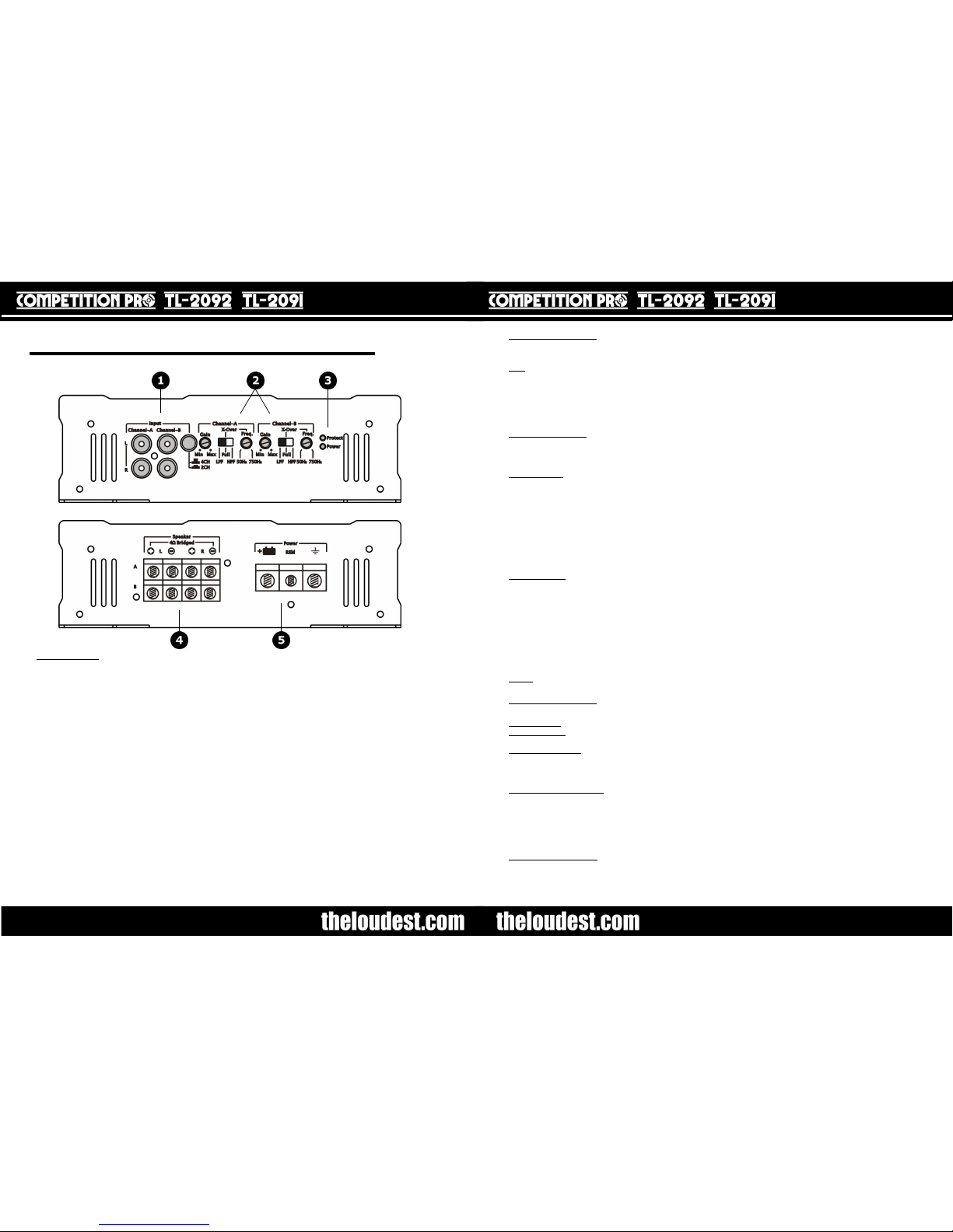
– This section is labelled “Channel-A” and features a gain control knob (“Gain”), a
crossover selector switch (“LPF / FULL / HPF”), and the variable crossover filter frequency control knob
(“Freq.”). The changes made here affect the speaker(s) connected to the Channel A output.
Gain - Turning the gain knob to the right (clockwise) will increase the volume, and to the left (anti-clockwise)
will reduce the volume. It is important to understand that the amount of gain needed is proportional
to the level of the signal coming from the source unit. For example, it is possible for the gain knob
to be at only a quarter of its maximum, but the amplifier is actually outputting to its full potential.
This could be because the source unit is supplying slightly more power than normally expected.
Please see “Installation” section for how to calibrate the amplifier to the output of the source unit using the
gain knob.
Crossover (“X-Over”) - The crossover switch has three settings, “LPF” (Low Pass Filter), “FULL” (No filter
applied / off) and “HPF” (High Pass Filter). If either the LPF or HPF are selected, the “Freq.” knob (variable
crossover filter frequency) is used to fine tune the filter. The knob controls the frequency at which the
attenuation starts.
Low Pass Filter – This filter lets low frequencies through, and cuts out high frequencies and should be used
when connecting subwoofers to the output. This will cut out high frequencies that the subwoofer(s) are not
designed to reproduce, and so only output the bass from the signal. The Frequ. knob controls the highest
frequency range that is sent to the subwoofer(s). The range is adjustable, from 50 to 500 Hz with a slope of
40 dB per octave. The value that this should be set to changes depending on the subwoofer(s), enclosure and
vehicle used. This can be set by starting with the knob position fully clockwise, then turning the knob anti
clockwise very slowly until the best result is heard. This may take some time to get exactly right. It is
advisable to play music of the genre that will most commonly be listened to as this is set. It is also advisable
to use different tracks when configuring the LPF.
When set correctly, the subwoofer is able to work more efficiently, and the upper frequency range reproduced
is configured to the equipment, surroundings and user taste.
High Pass Filter – This filter lets high frequencies through, and cuts out low frequencies and should be used
when connecting full range speakers such as 6”x9” speakers to the output. This will cut out sub/low bass
frequencies that the speakers can not reproduce at high volumes, and so allow the speakers to operate more
efficiently. The Frequ. knob controls the lowest frequency range that is sent to the speakers. The range is
adjustable, from 50 to 500 Hz with a slope of 40 dB per octave. The value that this should be set to changes
depending on the speakers used. This can be set by starting with the knob position fully anti clockwise, then
turning the knob clockwise very slowly until the best result is heard. This may take some time to get exactly
right. It is advisable to play music of the genre that will most commonly be listened to as this is set. It is also
advisable to use different tracks when configuring the HPF.
When set correctly, the speakers are able to work more efficiently, and the lower frequency range reproduced
is configured to the equipment, surroundings and user taste.
“FULL” – No filter is applied when the switch is set to “FULL”; the full range of frequencies are reproduced and
output to the speakers. In other words the filters are OFF.
2. Channel B Controls - This section is labelled “Channel-B” and operates in exactly the same way as the
above Channel A controls. The changes made here affect the speaker(s) connected to the Channel B output.
3. Indicators
Power indicator - This LED will light when power, remote and earth are all connected to the amplifier. If this
LED is not on, there is a problem with one of these connections.
Protection Indicator - This LED will light if the amplifier has detected a fault and if it is not already damaged,
has shut down to protect itself from permanent damage. This may be due to one of the following: low
voltage, excessive heat, short circuit or overload. If this happens disconnect the amplifier and investigate the
problem.
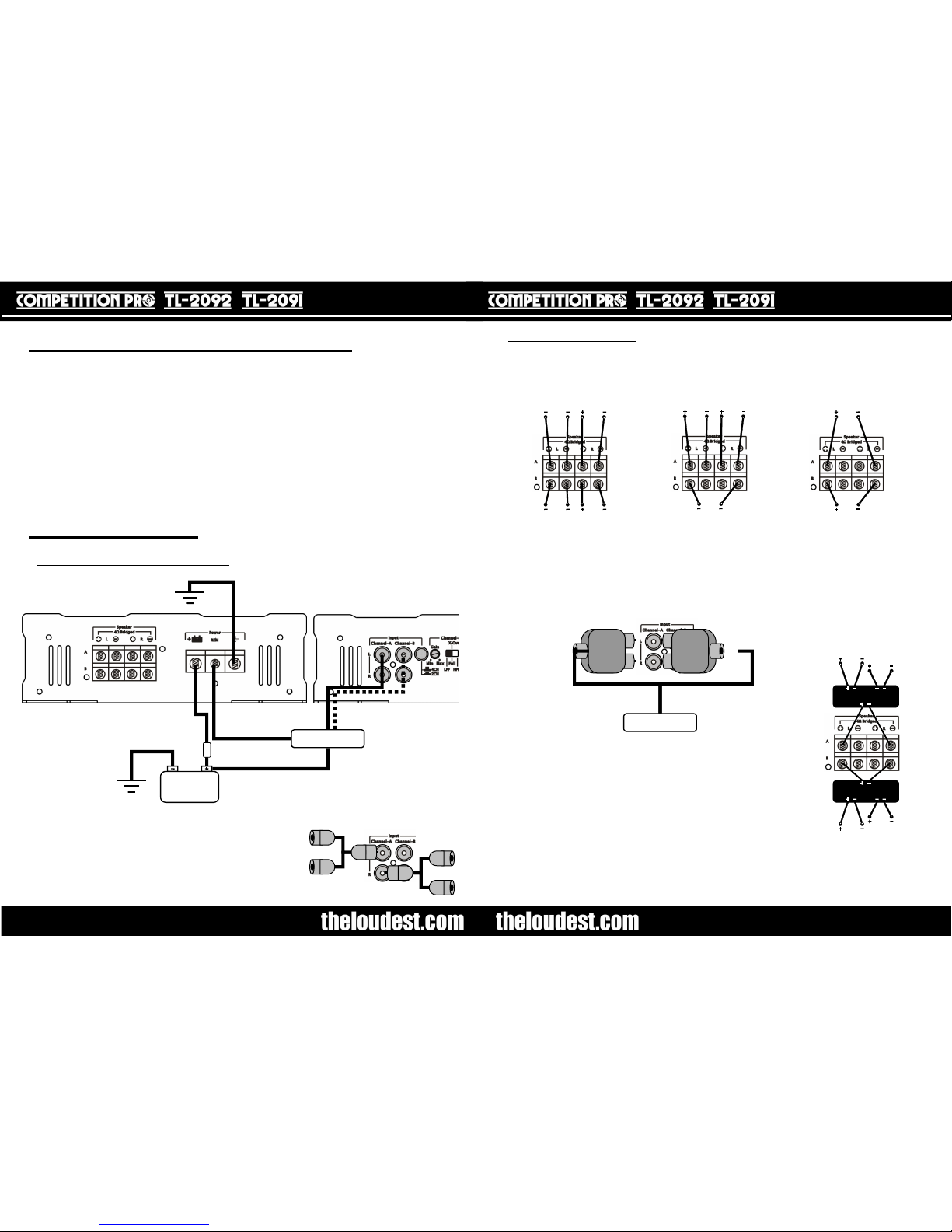
4. Speaker connections – This section is labelled “Speaker” and consists of Channel A outputs (left and right)
and Channel B outputs (left and right) and are in the form of screw terminals for attaching the speaker cables.
Undo the screw head enough to slot a stripped end of speaker cable into the terminal, and then tighten the
screw. Please see wiring diagrams in the “Installation” section for how to connect a range of
speakers/subwoofers to the amplifier. To operate Channel A or B in bridge mode,
connect “L” “+” to “R” “-”. The minimum load impedance when bridging is 4 ohm, the minimum load
impedance per channel when using L and R individually, is 2 ohm.
5. Power Connections – This section is labelled “Power” and is where all the power leads are connected to
the amplifier. Particular care must be taken when connecting, NOT to cross/touch any of the cables together.
From left to right, “+” is the positive connection from the battery, “REM” is the remote or ignition connection
and “-” is the negative or earth connection.
OWNER’S MANUAL
Side 2:
1. Audio Input
– This section is labelled “Input”, and features two pairs of RCA phono sockets, each pair
has one “L” (white - top), and one “R” (red - bottom) RCA socket. These are for the audio input from
the source unit. A source unit that supplies a “line level” (pre amp) audio output in the form of RCA
phono plugs is required to connect to the input (via a phono extension lead). A high quality shielded lead
is recommended as this will help reduce the possibility of noise entering the system.
Also featured on the “Input” is a 2-ch/4-ch switch. Essentially, this saves using splitter leads or adaptors
if only one RCA output is available, allowing one RCA input while utilising the full functionality of the 4-
channel amplifier.
With the 2-ch/4-ch switch off (not pressed in), two pairs of RCA inputs can be used. The input pair
plugged into the input “Channel-A”, will control the speaker(s) connected to the Channel A outputs, while
the input paid into the input “Channel-B”, will control the speaker(s) connected to the Channel B outputs.
With the 2-ch/4-ch switch on (pressed in), one pair of RCA inputs can be used. The input pair plugged
into the input “Channel-A”, will be used for both Channel A and Channel B outputs. This saves having to
use RCA splitting leads/adaptors.
To clarify, here are two examples:
1). The source unit has two RCA outputs, “front” and “rear”. Front is connected to Channel A input, and
rear is connected to Channel B input. A pair of front speakers are connected to the Channel A outputs,
and a subwoofer is connected to Channel B outputs. Settings at the source unit (such as gain, bass
boost, etc ) can be applied to Channel A (“front”) and Channel B (“rear”) independently at the source
unit. The 2-ch/4-ch switch is set to off (not pushed in).
2). The source unit has one RCA output. It is connected to the Channel A input. As in the first example,
a pair of front speakers are connected to the Channel A outputs, and a subwoofer is connected to
Channel B outputs. Settings at the source unit (such as gain, bass boost, etc) can not be applied to
Channel A and Channel B independently at the source unit, because both Channel A and Channel B are
sharing the same input. Any independent changes can be made on the side panel of the amplifier. The
2-ch/4-ch switch is set to on (pushed in).
Control Panel Functions
The control panels for the TL-2092 and TL-2091 are as follows:
OWNER’S MANUAL
Side 1:

Speaker connection diagrams
– Below are three diagrams that illustrate how to connect speakers
and/or subwoofers to the amplifier in different combinations. The speakers named “left” or ”right” can be
full range speakers or component speakers. In the event of component speakers being connected, it is
the crossover that the + and – of the channel connect to.
In the event that two extremely high power component speakers are to be connected to the amplifier
that require the amplifier to operate in dual bridge 2-channel stereo mode (one left output and one right
output), specific connections must be made, as detailed below.
OWNER’S MANUAL
LEFT
FRONT
SPEAKERS
REAR
SPEAKERS
RIGHT
LEFT RIGHT
SPEAKERS
LEFT RIGHT
SUBWOOFER
SUBWOOFER 1
SUBWOOFER 2
2CH/4CH SWITCH POSITION: 4CH
(NOT PRESSED IN)
SOURCE UNIT
RCA LEAD
LEFT
SIGNAL RIGHT
SIGNAL
SPEAKER
TWEETER
X-OVER
TWEETER
SPEAKER
TWEETER
X-OVER
LEFT
SPEAKERS
RIGHT
SPEAKERS
The input from the source unit must come in the form of an RCA pair (one
left and one right). The left RCA plug is connected to the input socket of one
of the supplied adaptors. The plugs on the adaptor are then placed onto the
“Channel-A” input sockets. It may be a tight fit, but the adaptor will be
securely held when pushed into place. This means that “Channel-A” is now
the left input/output side of the amplifier. The right RCA plug is connected to
the input socket of the other supplied adaptor. The plugs on the adaptor are
then placed onto the “Channel-B” input sockets. This means that “Channel-
B” is now the right input/output side of the amplifier. This is illustrated in
the diagram above this text.
Ensure that the 2ch/4ch switch is set to 4-ch (not pressed in).
The crossover connecting the left speakers connects to the Channel A bridge
output, and the crossover connecting the right speakers connects to the
Channel B bridge output. This is illustrated in the diagram to the right of this
text.
It is important to follow the instructions that start on page 7, while referring to the diagrams.
Power connection/RCA connection diagrams - Below is a diagram of the basic completed installation
of the power cables and RCA leads on the TL-2092 or TL-2091 amplifiers. The speaker connection
diagrams follow on the next page.
There are no RCA/phono outputs on the amplifier. RCA outputs on an amplifier enable a phono lead to
be used to connect the RCA output on one amplifier to the RCA input
on another amplifier. This can be useful in situations where only one
RCA output from the source unit is available.
Two phono splitter leads (or “Y” leads) have been included with the
amplifier to allow another amplifier to share the same RCA output
from the source unit if required. The leads convert one RCA socket
on the “L” input of the amplifier, into two RCA sockets, and convert
one RCA socket on the “R” input of the amplifier into two RCA
sockets, as illustrated in the diagram to the right of this text.
Installation
OWNER’S MANUAL
Mounting Instructions
Before mounting, please read the “Installation” section. The best place to mount the amplifier is
somewhere where it will not get damaged, eg. by items in the boot of the vehicle. The amplifier
dissipates heat using its heat sink; somewhere with sufficient space and air would be fine. Therefore
placing the amplifier in-between items, placing items on top of it, or mounting it upside down is not
advisable.
Examples of surfaces to mount on are: the floor of the boot, fake floor of boot (MDF) or side of boot.
Never mount the amplifier on the side of a subwoofer box as this can damage the amplifier. Never
mount the amplifier outside of the car, in the engine bay or anywhere where it has a risk of getting wet.
Normally it is best to attach the amplifier to a board, and then attach the board to the car body. This is
good practice to avoid noise problems.
Before mounting, make sure that the surface is suitable and free from any obstructions. Use the
amplifier as a template and mark where the holes are to be drilled with a pencil or pen. Drill the pilot
holes with a drill bit of diameter smaller than that of the screws.
Then place the amplifier on the surface and tighten the screws until they are holding the amplifier
securely in place.
ALREADY INSTALLED
ALREADY INSTALLED
EARTH/GROUND CABLE
FUSE
RCA LEAD(S)
POWER CABLE REMOTE CABLE SOURCE UNIT
BATTERY

OWNER’S MANUAL
connected to the amplifier in the same way that the power cable connected to the positive
terminal of the amplifier), the other end has a ring connector installed and is to be bolted to
the earthing point.
Connect the remote cable (thin blue wire) from the source unit’s (head unit’s) remote
output. This is called a variety of things including “remote”, “aerial”, “electric antenna”, “REM”
and “remote turn on”. To do this you will need to have access to the back of the source unit; it
will need pulled out. Please refer to the source unit’s manual to find the right wire to use.
When the remote cable is attached to the remote output of the source unit, leave the source
unit pulled out for the moment, and run the remote cable to where the amplifier is, down the
same side of the vehicle as the power cable. As with the power cable, try to hide it under
panels and carpet. Slide the connector into the “REM” terminal and tighten.
Connect the audio signal lead(s) (RCA phono leads) to the “line level(s)” or “pre-out(s)” of
the source unit. The pre-out(s) of the source unit should be in the form of two RCA phono
sockets. Simply plug your lead into the sockets, ensuring red goes to red, and white (or black)
goes to white (or black). Then run the lead all the way to the amplifier. To minimise noise,
please ensure that the audio signal lead is run well away from the power leads. It is normally
best to run it down the opposite side of the car. If the cables are too close, a high
pitched whine can get into the system; this is engine noise.
If your source unit has no pre-outs, it is probable that it is not of sufficient quality to work well
with the amplifier; if it is giving poor quality audio then the amplifier will simply amplify this
poor quality audio. However, if a line output converter is purchased, it would convert speaker
outputs to a line level and enable you to operate the amplifier. As mentioned, the output may
not be of a great quality.
Connect the speaker cable from your speaker(s) (and/or component(s)/subwoofer(s)) to the
amplifier. Some configurations are illustrated on page 6. It is advisable to cut the speaker
cable to size. Never connect or disconnect speakers when the amplifier is on; you risk
permanently damaging the speakers.
Once you have checked that all the connections are good and solid, re-connect the negative
terminal of the battery. If anything goes wrong, disconnect it immediately and investigate.
The amplifier’s power LED should be lit. If not, or the protection LED is lit, please refer to the
“Troubleshooting” section.
Finally, all that is left to do is calibrate the amplifier and speakers with the source unit:
1. If using brand new speakers, do not proceed to the next step until you have “run in” the
speakers by playing music at relatively low-medium volumes for approx 20 mins.
2. Turn the gain knobs on the amplifier all the way down.
3. If applicable, select the required filters on both the channel control panels.
4. Play a CD or similar of music or audio that will be typically played.
5. Turn the gain control on the source unit to around 70 – 80% of it’s maximum.
6. Slowly increase the gain knob of each channel on the amplifier until you can hear
distortion, one at a time.
7. Turn the gain knob on each channel of the amplifier to just before this distortion occurs
(if no distortion can be heard, this is fine!).
8. Test the system and make any equalisation changes on the source unit or the amplifier
(frequ. knob if using the filters) according to taste, it may take some time to adjust all
the amplifier settings to get the most from the setup.
9. If any equalisation changes are made, repeat stages 2 to 8 until satisfied
10.Never exceed the source unit gain that you used to calibrate the system, and
NEVER continue to operate speakers if you can hear distortion as this will
damage the speakers.
Remember: It is possible for the amplifier gain knobs to be at only a quarter of their
maximum, but the amplifier is actually outputting to its full potential. This could be because
the source unit is supplying slightly more input power than normally expected.
OWNER’S MANUAL
Installation Instructions
If you do not have sufficient experience or tools to carry out the installation, it is
imperative that you seek the assistance of someone who does, or have the amplifier
professionally installed.
TheLoudest.com accepts no liability for any damage resulting to vehicle components when
installing or operating the amplifier. It is the sole responsibility of the user to follow these
instructions carefully and seek professional advice if required.
The TL-1191 3000w amplifier wiring kit is strongly recommended for use with the TL-2092
amplifier. It contains the components mentioned in the installation instructions below. Failing
this, 4 AWG power/earth cable and an 80A fuse installed in the power cable is an absolute
minimum.
The TL-1192 2000w amplifier wiring kit is strongly recommended for use with the TL-2091
amplifier. It contains the components mentioned in the installation instructions below. Failing
this, 8 AWG power/earth cable and a 60A fuse installed in the power cable is an absolute
minimum.
Before starting the installation it is advisable to disconnect the negative terminal of the
vehicle battery. This ensures the battery will not short if the wires are accidentally crossed
during installation, and is generally good practice when making electrical changes.
Please be warned that after disconnecting the battery, your control unit (head unit) may
require a code to be entered, some car alarms may also sound. Therefore it is best to disable
the alarm before installation and enable it again after installation is complete.
Connect the power (+) cable (red cable) directly to the positive terminal of your vehicle
battery by unscrewing the nut on the positive terminal and slipping on the power lead
connector, before replacing and tightening the nut. The TL-1191/TL-1192 wiring kits include a
battery terminal block which ensures a very clean connection. There is a fuse holder and fuse
already installed on this cable if purchased as part of the TL-1191/TL-1192 wiring kit. If not
using the kit, you will need to install one about 60 cm from the battery (using an 80A fuse for
TL-2092, or using a 60A fuse for TL-2091).
This power cable then needs to be run to where the amplifier will be mounted. Look around
the engine bay for a place to run the cable through to the inside of the vehicle. Suitable points
are usually bonnet pull grommets or air intake holes. This positive wire needs to be protected
from damage. Failure to protect it from damage could lead to a vehicle fire. When you have
been able to feed the cable to the inside of the car, try to hide the cable as well as possible on
its way to the amplifier (under carpet, or inside panels).
The TL-1191/TL-1192 kit includes a connector already installed on the end of the power cable;
this will need to be removed for the cable to be connected to the amplifier. Strip the end of
the cable and slide the end into the power (+) terminal of the amplifier, and then tighten.
Competition Pro amplifiers are capable of delivering extremely high power levels. Therefore
tight, reliable and clean power connections at both ends are very important, and ensure
maximum performance.
Connect the earth (-) (or ground) cable (black cable) to a solid, bare metal point on the
vehicle’s chassis. A common place for this is the boot catch; however any existing substantial
bolt or screw that makes contact with the car’s body near the amplifier is sufficient (connection
must be made to bare metal, so any paint at the connection point must be stripped). If there
is no existing point, you can make one by drilling into the car’s body. This should be done
carefully as a last resort, ensuring that none of the car’s electronics or any other component is
going to be damaged. A clean connection is needed, so scraping away the paint for the
connection is required. The length of the earth cable needs to be a short as possible, the one
supplied with the TL-1191/TL-1192 kit will connect to the negative (-) amplifier terminal (if a
ring is installed already on the cable, this will need to be removed so that the cable can be

OWNER’S MANUAL
Troubleshooting
Problem
Possible Cause(s) Solution
Power LED off No (or poor) power, remote or
ground connections
Blown fuse
Verify connections both at amplifier and at
other ends
Replace Fuse
No Output
(Power LED on) Earth cable not connected
Speakers not connected
Gain down on either amplifier or
source unit
Speaker(s) blown
Faulty/disconnected RCA leads
Check earth cable at amplifier end and vehicle
chassis end
Verify speaker connections at amplifier, and
also at the speakers
Verify gain/eq controls
Disconnect speakers one at a time to pinpoint
defective speaker
Check/replace RCA leads
No Output
(Protect LED on) Amplifier is overheated
Vehicle’s battery is supplying
something other than 12V
Review mounting position and conditions
Check vehicle’s battery and charging system
Distorted output Source unit/amplifier gain set too
high
Source unit is not capable of good
audio reproduction
Speaker(s) blown
Re-calibrate amplifier with source unit
Replace/upgrade source unit
Disconnect speakers one at a time to pinpoint
defective speaker
Bass is weak Dual voice coils on subwoofer
wired out of phase
Bad speaker connections
Subwoofers connected out of
phase
Eq settings are reducing bass
power
Poor quality subwoofer(s)
Enclosure too small for subwoofer
Try swapping over + and – on one of the voice
coil connections
Check speaker connections at subwoofer and
amplifier ends
Check the + and – connections all match,
swap to test
Verify all eq settings on amplifier and source
unit, especially “subsonic” and “LPF” settings
on amplifier
Use TL-1122 subwoofer(s)
Increase enclosure size
Blowing fuses Excessive output levels Lower gain
Amplifier switches on
and off No (or poor) power, remote or
ground connections
Low voltage from battery
Verify connections both at amplifier and at
other ends
Test battery, replace if necessary
If your amplifier is still not functioning correctly after checking through the “troubleshooting”
section, please contact our support team at:
support@theloudest.co.uk
OWNER’S MANUAL
Safety
Health Warning
The Competition Pro range of car audio is built for very high power handling. Listening to
music at such high powers is potentially capable of causing physical side effects such as
nausea or even permanent side effects such as hearing loss. It is therefore absolutely
essential that conservatism and a high sense of judgement are observed when in
operation.
TheLoudest.com accepts no liability for hearing disorders, nausea or other side effects
caused by this equipment.
General Safety
Playing loud music in a vehicle can hinder your sense of what is going on around you on
the road, including your ability to hear your vehicle, and other vehicles around you. We
recommend listening at low or moderate levels while driving.
TheLoudest.com accepts no liability for injury, property damage or otherwise resulting
from the use or misuse of this equipment.
Do not use any chemicals when cleaning this equipment. Please use a clean dry cloth.
Do not install this unit outside the car, or anywhere where it could become damp or humid,
or where it can become exposed to the sun. It should be installed in a dry and ventilated
area inside the car.
Never connect or disconnect phono/RCA inputs or speakers when the amplifier is on; this
can permanently damage the speakers. Always do this when it is off.
Never open the amplifier up. Doing so would put you at risk of an electric shock. None of
the internal parts are serviceable by the user. In the case of the unit needing repair or
maintenance, please take it to a qualified professional.
This manual suits for next models
1
Table of contents