Cyfre CHACDMA-819 User manual

Dual Band CHACDMA-819 Amplifier Installation Manual
Page 1 of 3
All brands and trademarks are the property of their respective owners. Copyright
2003, Janizary Holdings, Inc. All rights reserved.
Rev h D00000515
Designed and manufactured in North America
Manufactured under license from Motorola Inc.
Note: Before installing the Cyfre™Amplifier, please read the entire contents of this manual.
Section # 1 Parts List
Item Qty Description
1 1 CyfreTM Signal Amplifier
2 1 2 Meter (78”) DC Power Cable
Section # 2 Tools and Other Materials Required
Item Description
1 Electric drill (as required for signal amplifier mounting holes)
2 Screw driver
3 Qty 4 screws (length and type as required for signal amplifier mounting)
4 Wire cutters / strippers
5 Qty 2 wire connection insulators or insulating material (as required for DC power cable connection to 12V DC system)
Section # 3 WARNINGS!
∇Directly wired vehicle antennas, mounted a minimum distance of 20 cm (7.87 inches) away from the body of any
user or nearby persons is recommended.
∇Mounting an amplifier in the engine cavity or on the underside of the vehicle will void the manufacturer’s warranty.
∇Subjecting the amplifier to voltages greater than 30 Volts DC will damage the amplifier and void the manufacturer’s
warranty.
∇Any vehicle with an electrical system of greater than 30 Volts DC should use a step-down voltage regulator to bring
the voltage within the DC operating power range of the amplifier (10 to 30V dc).
∇Under no circumstances should the amplifier be powered up without a properly connected 50 ohm 800/1900 MHz
dual band cellular/PCS antenna or the amplifier may be damaged, resulting in the manufacturer’s warranty being
void.
∇For optimum performance and compatibility with cellular service provider requirements, it is recommended that an
external antenna with a maximum gain of 3dB be installed.
∇Use of cellular amplifiers with antennas of higher gains than 3 dB gain is in violation of FCC regulations for which
the offender will be fully liable, and warranty claims will be voided.
It is recommended that only certified automotive installation technicians install this product in a vehicle. Installation
by any other person is at the risk of the vehicle owner and operator.
Section # 4 Installation: Selecting a Suitable Location To Mount The Signal Amplifier

Dual Band CHACDMA-819 Amplifier Installation Manual
Page 2 of 3
All brands and trademarks are the property of their respective owners. Copyright
2003, Janizary Holdings, Inc. All rights reserved.
Rev h D00000515
Designed and manufactured in North America
Manufactured under license from Motorola Inc.
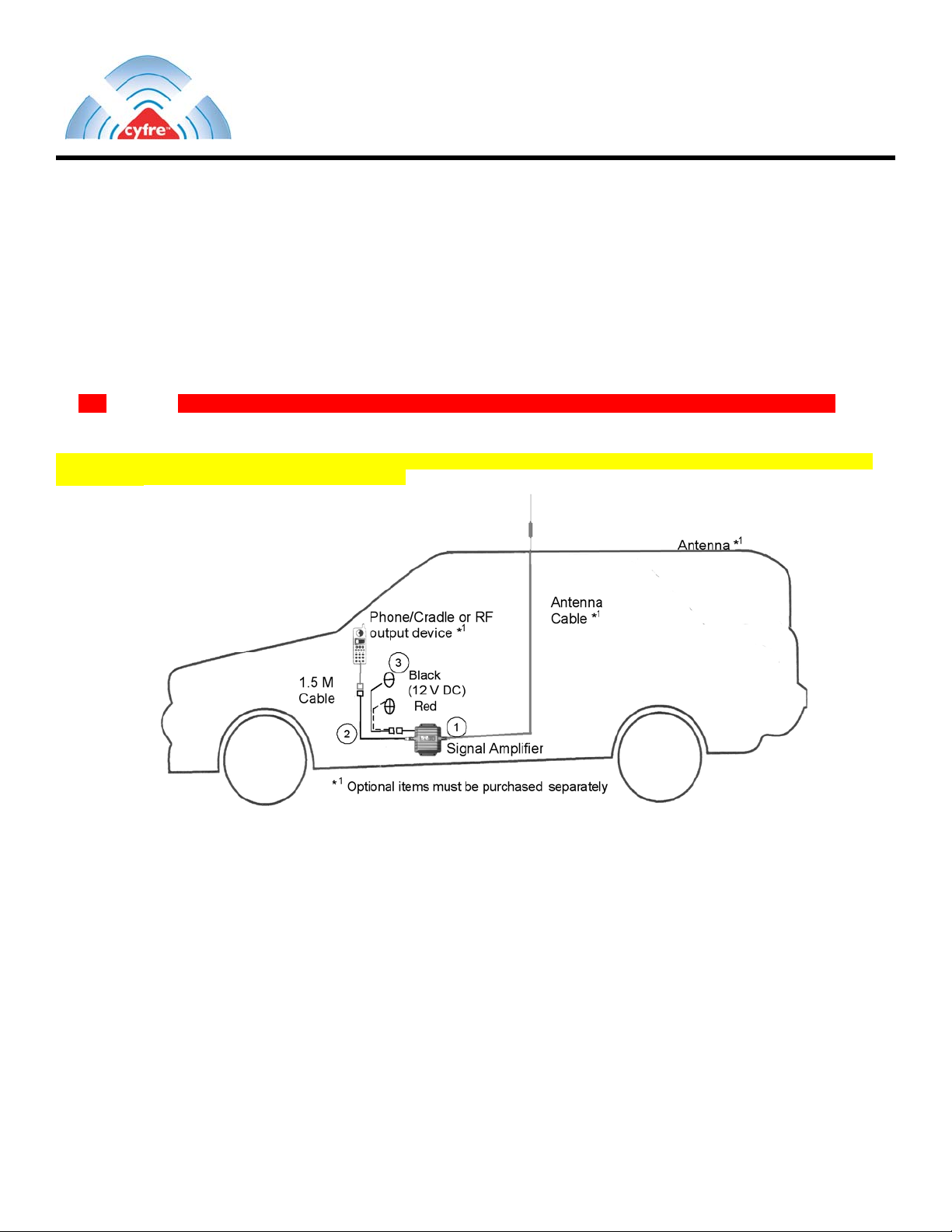
Locate a suitable place to mount and conceal the signal amplifier. Suggested mounting locations include: under the dashboard,
under the seat, or in the trunk.
For peak performance the signal amplifier should be mounted as close to the phone handset as possible. The amplifier’s
location should be easily accessible and mounted away from moving parts, as well as excessive heat and moisture.
Section # 5 Installation Cautions
∇Use caution to avoid drilling through or near fuel lines or fuel tanks; brake lines; or electrical wiring.
∇Do not mount the amplifier or its associated wiring in a location that may interfere with the safe operation of the
vehicle.
∇If the fuse is changed from the 3 amps to a higher rating the warranty is void. Purchaser of the amplifier would be
responsible for the repair of the unit.
∇Caution: Connection to the negative side with the positive lead will cause damage to the amplifier.
Section # 6 Installation Of The Signal Amplifier
To meet the FCC Exposure Guidelines, the antenna should be installed so there is at least 20 cm of separation between the
body of the user or nearby persons and the antenna.
Typical Installation For Under The Seat Mounting
1. For safety, disconnect the vehicle’s negative “−“ battery terminal to remove power from the vehicle.
2. Drill holes and mount the signal amplifier (ITEM 1) in the selected location.
3. Connect the red wire of the supplied 2 Meter (78”) power cable (ITEM 2) for the signal amplifier to a positive connection on
the vehicle’s electrical system. Choose a 10 to 30 Volt DC circuit that is: fuse protected; and ignition switched. (Often
referred to as the “Accessory output”)
4. Attach the solid black wire of the supplied 2 Meter (78”) power cable (ITEM 2) to a vehicle electrical ground point.
5. Attach an external antenna cable (7dbi max) to the amplifier's antenna connector. The “Phone” connector on the amplifier is
connected to a cellular phone handset via a RF cradle or an RF cable. You may also connect the optional RF cable for your
handset, from the cellular handset to amplifier port labelled “Phone”.
6. Reconnect the vehicle’s negative “−“ Battery terminal.
Section # 7 Limited Warranty
Cyfre™ warrants that this product is free from any defects in material or workmanship for a period of one year. If a defect in
material or workmanship is found, Cyfre™ agrees to repair or replace the product at its own discretion, free of charge to the
Use a 3dB
antenna for
Optimal
Performance

Dual Band CHACDMA-819 Amplifier Installation Manual
Page 3 of 3
All brands and trademarks are the property of their respective owners. Copyright
2003, Janizary Holdings, Inc. All rights reserved.
Rev h D00000515
Designed and manufactured in North America
Manufactured under license from Motorola Inc.
original purchaser. Please return the product along with proof of purchase to the original authorized dealer. This warranty is null
and void if the product has been modified, abused, tampered with, subjected to abnormal conditions, if the fuse is changed to a
higher rating than 3 amp, or transferred to someone other than the original purchaser.
Table of contents