9
Vacuum Pump Instructions for Use
3.5 Supply Voltage Selection
The Vacuum Pump can operate on the voltage range 100 – 240 VAC, 50 – 60 Hz. No fuse selection is required.
If the voltage is changed, it may be necessary to replace the Power Cord to an appropriately rated Power Cord.
Ensure that the correct Power Cord is connected.
3.6 Electromagnetic Compatibility
The Vacuum Pump is designed to provide a reliable controlled source of vacuum. It has been tested and found to
comply with the electromagnetic compatibility (EMC) limits for medical devices as specied by IEC 60601-1-2:2007.
These limits are designed to provide reasonable protection against harmful interference in a typical medical
installation.
Medical electrical equipment requires special precautions regarding EMC and must be installed and operated
according to these instructions. It is possible that high levels of radiated or conducted radio-frequency
electromagnetic interference (EMI) from portable and mobile RF communications equipment or other strong or
nearby radio-frequency sources could result in performance disruption of theVacuum Pump. Evidence of disruption
may include erratic readings, equipment ceasing to operate, or other incorrect functioning. If this occurs cease
using the Vacuum Pump and contact your Cook authorised service agent.
Refer to the tables in § 8 of this manual for guidance on electromagnetic emissions, electromagnetic immunity,
and recommended separation distance between portable and mobile RF communications equipment and the
Vacuum Pump.
3.7 Device Placement
The Vacuum Pump should be placed on a level secure surface, away from heaters, coolers, air-conditioning outlets,
mists, splashes and exposure to direct sunlight. It must not be placed in the presence of ammable gases.
The ambient temperature should be between +5°C and +35°C for the Vacuum Pump to function correctly. Position
the vacuum pump such that quick and easy disconnection of the power supply plug is not impeded.
3.8 Connection to the Foot Pedal
• Connect the Foot Pedal to the Foot Pedal Connection on the rear of the Vacuum Pump.
• The connection must snap into place with an audible click.
• Release the plug by pressing on the sides of the Foot Pedal Connection.
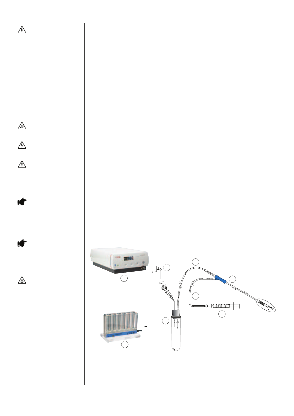
3.9 Vacuum Line and Filter
The Vacuum Pump uses a disposable Vacuum Line with Hydrophobic Filter (re-order code K-DVLF-240).
To prepare and install:
• Connect the silicone tube attached to the lter to the Patient Tube Connection on the Vacuum Pump.
• Connect the luer tting of the disposable Vacuum Line to the vacuum supply luer tting of the needle set.
• Connect a Syringe to the Flushing Line of the needle set (if required).
Note: This diagram indicates a Cook K-OPSD needle set.
The set up is complete and now ready for use.
WARNING: ELECTRIC SHOCK
HAZARD. Determine if the available
voltage corresponds to your device.
Connecting to the wrong voltage
will cause the Vacuum Pump to
malfunction or may permanently
damage the device!
The Power Cord must be equipped with
a safety plug. Use the enclosed Power
Cord for the connection between the
power plug and the device socket!
WITHIN THE U.S.A – Use only a listed
detachable Power Cord, type SJT,
minimum 18AWGx30, 3 conductors,
one end congured for NEMA 5-15,
other end for IEC320/CEE22!
To avoid the risk of electric shock this
equipment must only be connected to
a supply mains with a protective earth!
WARNING: EXPLOSION
HAZARD. Do not use the Vacuum Pump
in the presence of ammable gases!
WARNING: ELECTRIC SHOCK
HAZARD. Do not immerse the Vacuum
Pump!
WARNING: The Vacuum Pump
should not be used adjacent to or
stacked with other equipment. If
adjacent or stacked use is necessary,
the device should be monitored
to verify normal operation in the
conguration in which it will be used.
IMPORTANT NOTE: Use of
cables other than those specied or
provided by the manufacturer of this
equipment could result in increased
electromagnetic emissions or
decreased electromagnetic immunity
of this equipment and result in
improper operation.
IMPORTANT NOTE: The
Disposable Vacuum Line and
Hydrophobic Filter (K-DVLF-240) has
been designed and tested to handle
the full vacuum range of the device.
Other vacuum lines may not be able to
withstand the full vacuum range.
WARNING: BIOLOGICAL
HAZARD. Always use the
disposable Vacuum Line with
Hydrophobic Filter (K-DVLF-240). Never
use the device if there is any indication
that the tubing, the lter or the
Vacuum Pump is contaminated.
If the Vacuum Pump is suspected to be
contaminated, do not allow further use
of the device and immediately notify
your authorised service agent to have
the device checked and repaired.
The disposable Vacuum Line with
Hydrophobic Filter attached to the
Vacuum Pump are for single patient
use only and must not be re-used
or resterilised. Re-use of this device
may result in cross-contamination
which may lead to the transmission
of infectious diseases. Re-sterilisation
of this device may compromise the
structural integrity of the device and
cause product failure. Once used, this
product is considered as infectious and
should be disposed of according to local
policy for disposal of biohazard waste.
3
4
5
6
7
8
1
2
1. Vacuum Pump 5. Double Lumen Needle
2. Disposable 6. Syringe
Vacuum Line with
Hydrophobic Filter
3. Aspiration Line 7. Test Tube
4. Flushing Line 8. Test Tube Heater