4
ALL ABOUT IMAGE RECOGNITION & PROCESSING
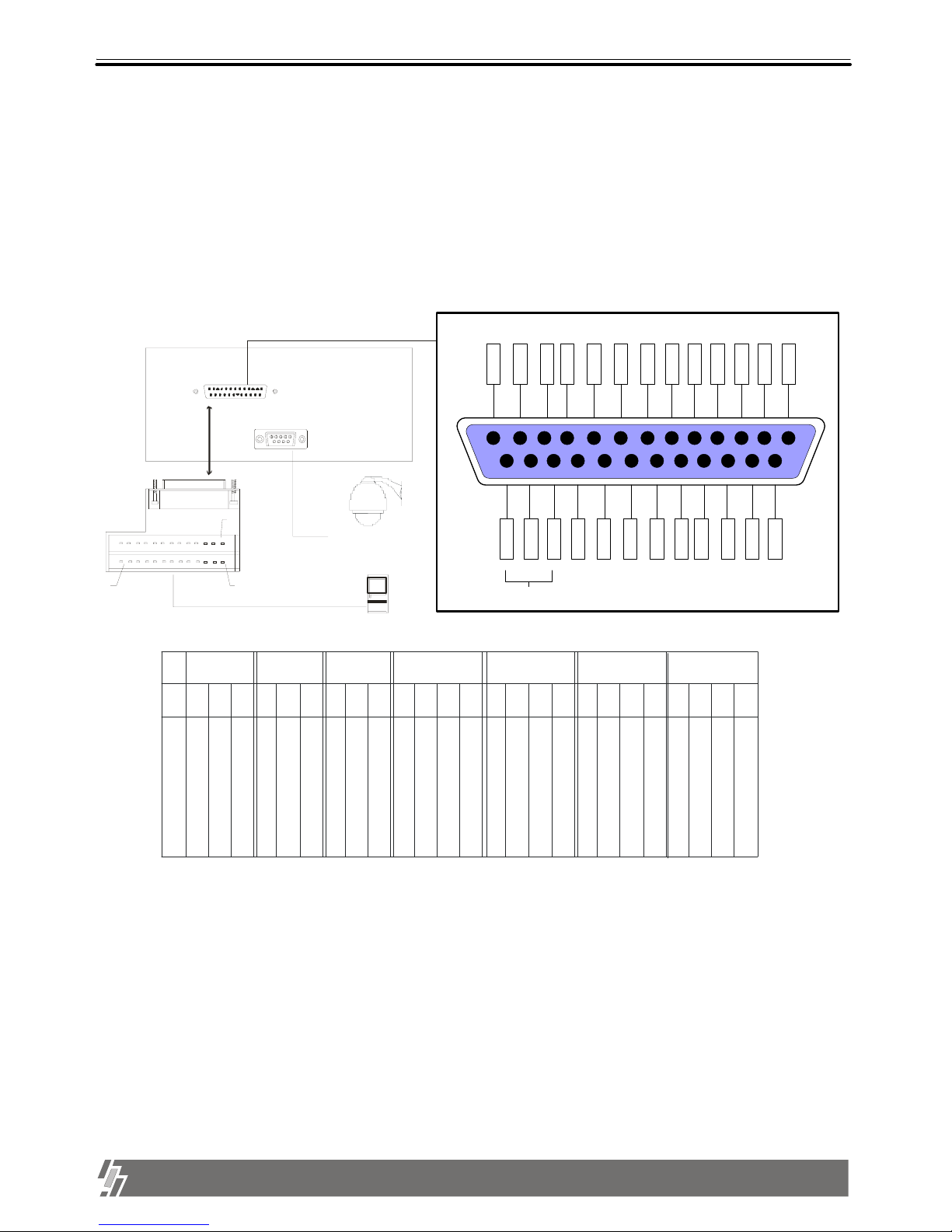
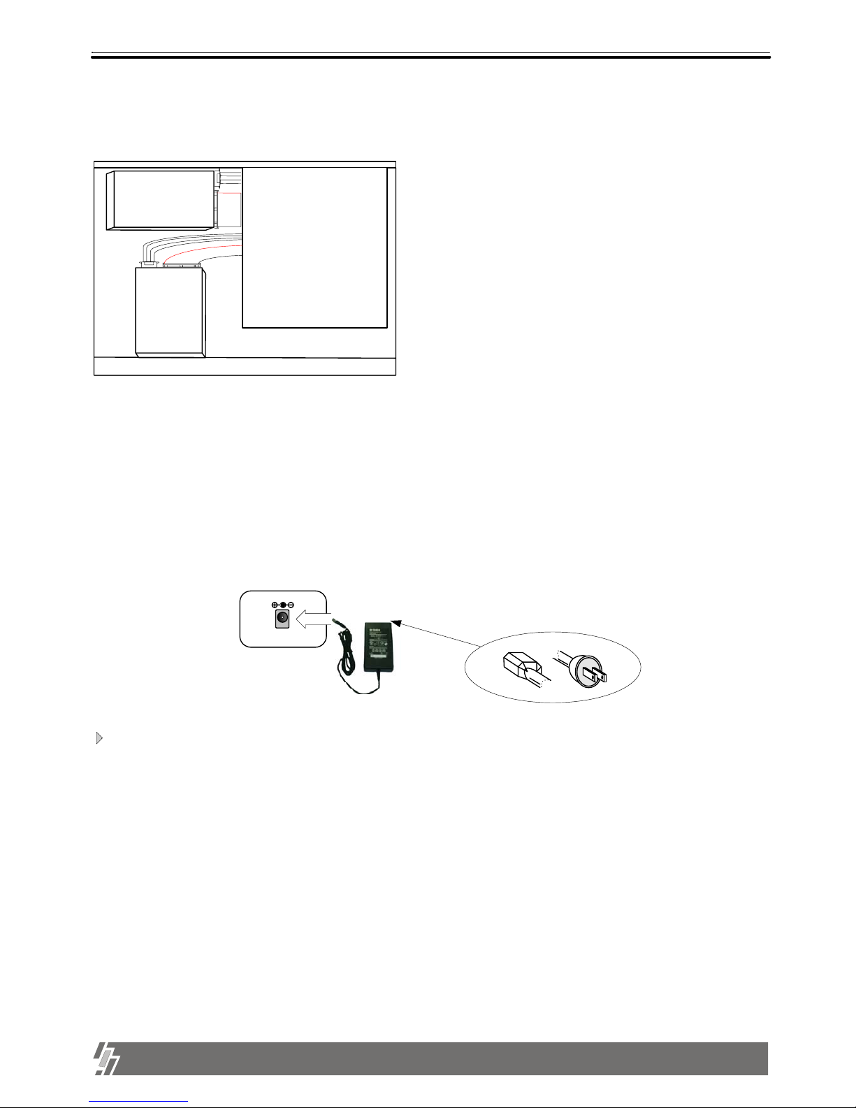
15-VP16-HDD2 & 15-VP16-CDRW
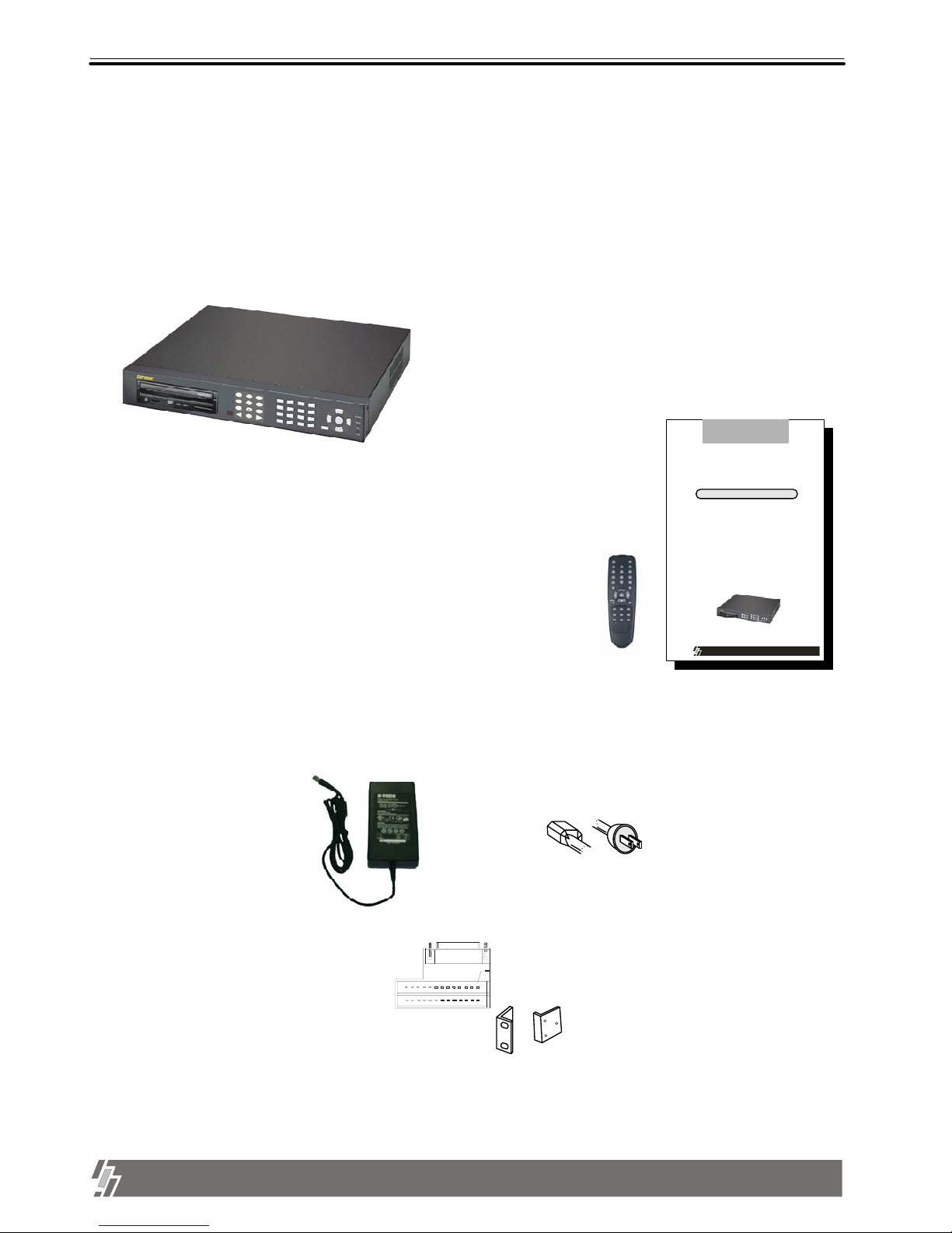
1. Product package
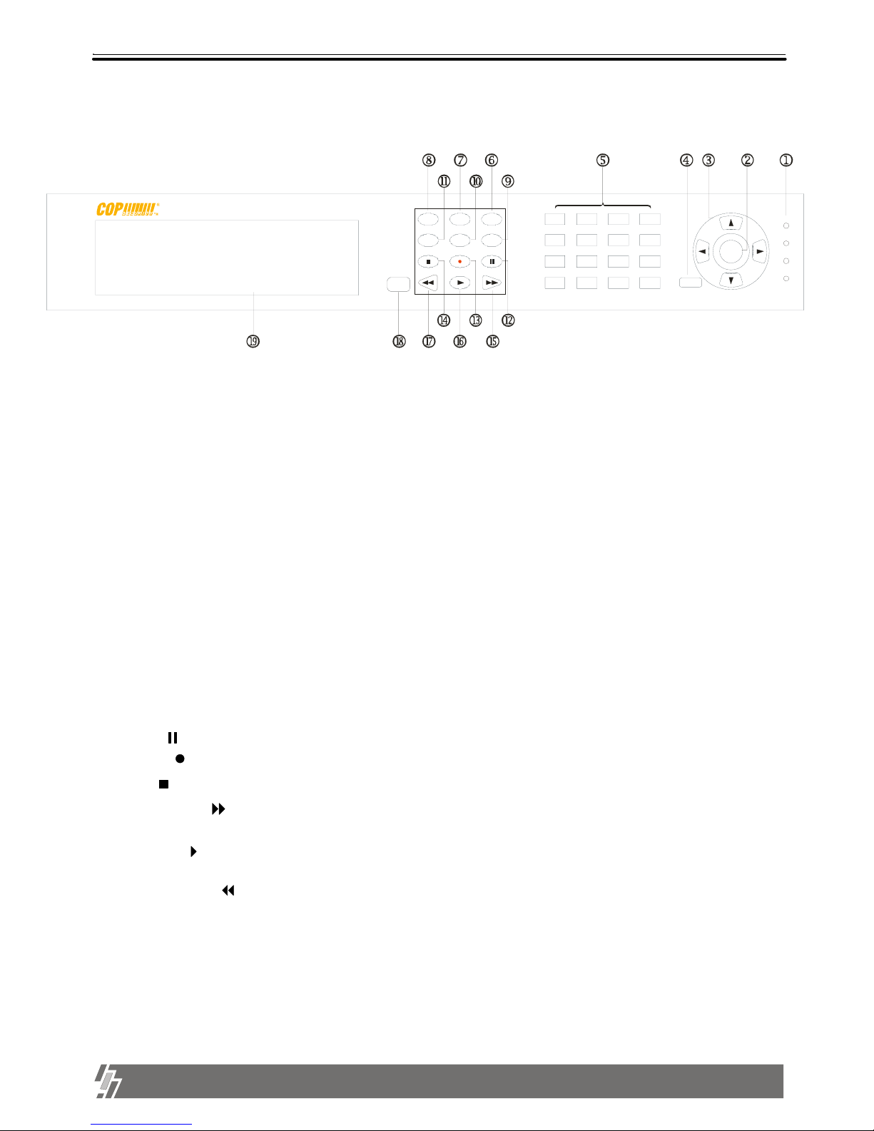
8. MODE : Change to 4-split, 9-split, or 16-split screen,respectively.
9. P/T : Enter into or exit from PAN/TILT CONTROL mode
If you press this button long times consecutively, it changes to screen position adjustment mode.
In case position of 16-split screen is not in the center of display unit, you can adjust screen position using
[UP],[DOWN], [LEFT], and [RIGHT] button. After adjustment, press [P/T] button once more long time to exit.
10. PIP : In full screen, this button creates PIP( Picture In Picture ) in rotation.
7. FRZ : On-off switch to freeze pictures in live mode
6. SEQ : In full screen, this button shows pictures in rotation.
11. ZOOM : In full screen, this button enlarges pictures two times ( Possible to fix area to be enlarged using
direction buttons.)
18. IR receiver : If blocked up by any object, remote controller does not work.
Notice : If several keys are pressed at the same time, or improper sequence in pressing
buttons may cause malfunction of unit.
1. LED : Indicates the status of system (OVERWRITE / RECORD / PLAY / SETUP)
[ Front Panel ]
1-2. Name and function of each button
19. CD-RW or Mobile Rack : Back-up/Recording device
13
1
9
5
15
11
7
14
10
2
6
16
12
34
8
Enter
Menu
Setup
Pl ay
Record
Ov e r w r i t e
MODE
ZOOM
SE Q
P/ T
FRZ
PI P
13. Record ( ): Records picture data on hard disk drive
14. Stop ( ): Stops recording or playback
17. Fast backward ( ) : High speed playback in reverse direction in playback mode, or moving to the
start of recorded data when it is in stop mode
16. Playback ( ) : Playback when it is pressed shortly in stop mode, or playback in reverse direction when
it is pressed in playback mode. Enter into GO TO menu in case pressed in longer time in stop mode.
15. Fast Forward ( ): High speed playback in forward direction in playback mode, or moving to the last of
recorded data when it is in stop mode.
12. Pause ( ): Pauses when it is in palyback mode
4. MENU : Used to change menu in SYSTEM SETUP
2. ENTER : Used as selection key in SYSTEM SETUP or changes contents displayed in live display.
this button repeatedly in live display mode, contents of display, that are, time and date, By pressing
status, and camera title, is included or excluded, and you can select any one of 8 choices.
5. Camera No : Represents camera numbers. Used with MODE button or to enter numbers.
3. Direction key : (UP, DOWN, RIGHT, LEFT Buttons)
Used to move in SETUP menu, or to change values.