Cosmotronic VPRTEX User manual


VORTEX USER MANUAL
by Simon De Rycke / BRiES
Thank you for purchasing VORTEX by Cosmotronic. VORTEX is a versatile analog
dual triangle core complex oscillator with a wide frequency range, a lot of timbral
shaping options, useful normalizations, CV inputs for every parameter and
attenuators to control the amounts of both internal and external modulation.
Contents of the box: width: 26HP
VORTEX depth: 27 mm
1 ribbon cable current draw: 190 mA +12V
4 black M3 mounting screws 190 mA -12V
1 Cosmotronic sticker 0 mA 5V
VORTEX / Complex Oscillator 1

TABLE OF CONTENTS
CONNECTING VORTEX .......................................................................................................... 2
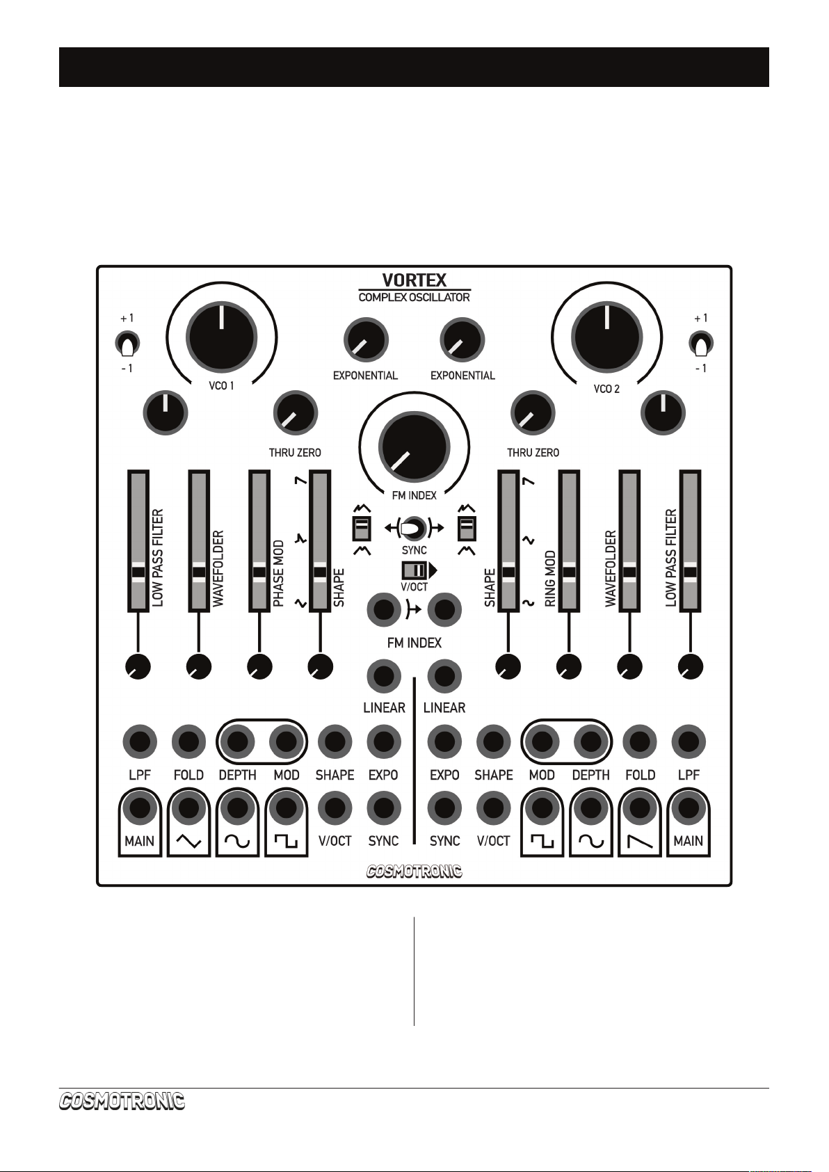
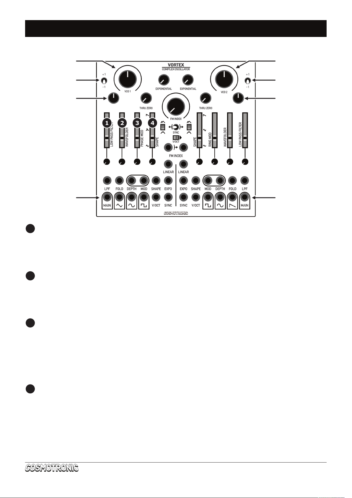
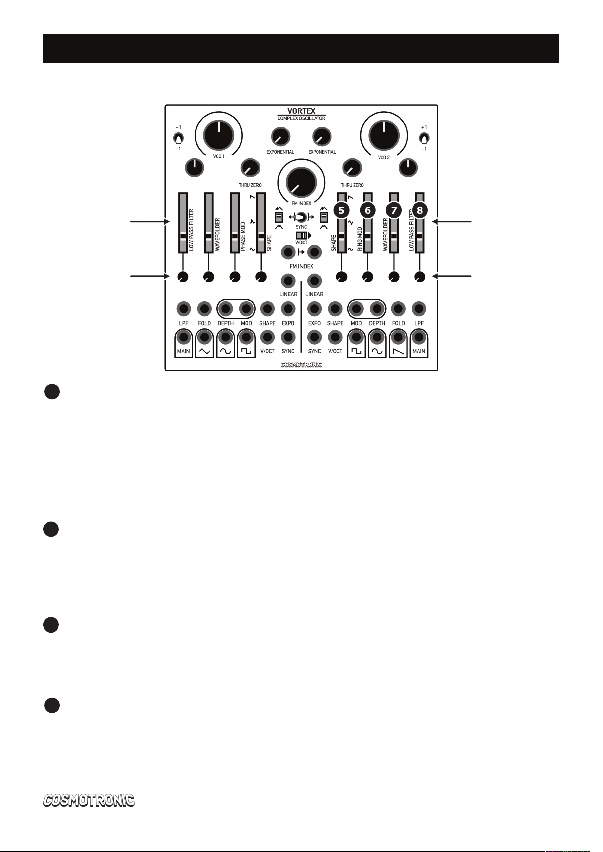
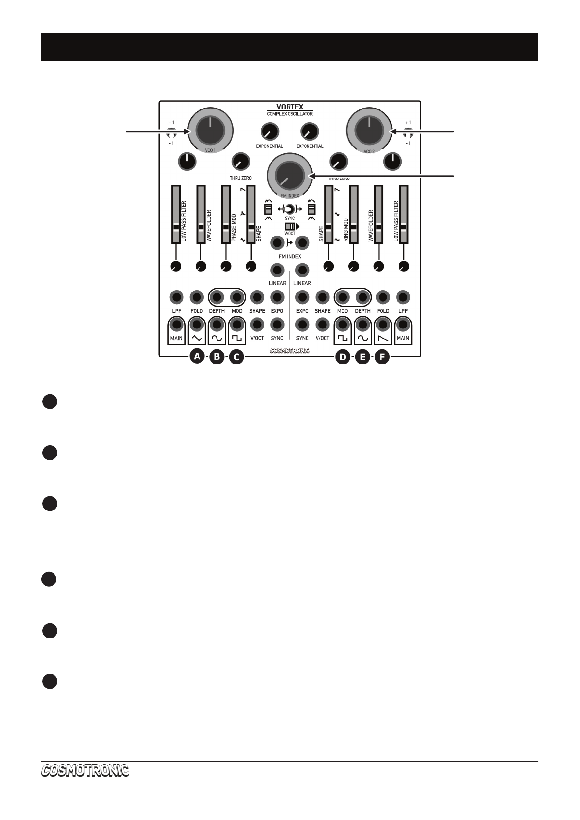
FRONT PANEL FEATURES ...................................................................................................... 3
VCO 1 ................................................................................................................................ 8
shape ............................................................................................................................. 8
wavefolder ...................................................................................................................... 9
phase modulation ........................................................................................................... 10
low pass lter ................................................................................................................ 11
VCO 2 .............................................................................................................................. 12
shape ........................................................................................................................... 12
ring modulation .............................................................................................................. 13
wavefolder .................................................................................................................... 14
low pass lter ................................................................................................................ 14
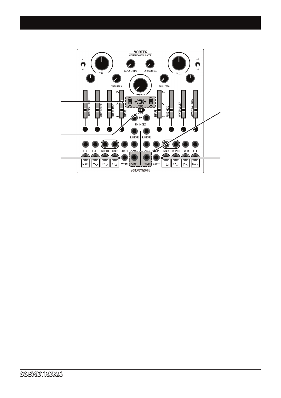
SYNC ............................................................................................................................... 15
sync toggle switch .......................................................................................................... 16
hard sync / soft sync ...................................................................................................... 16
sync inputs .................................................................................................................... 16
use more sync ............................................................................................................... 16
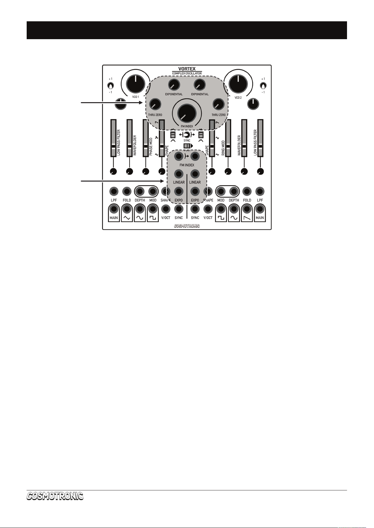
FREQUENCY MODULATION .................................................................................................. 17
through zero linear fm .................................................................................................... 17
exponential fm ............................................................................................................... 18
fm index ........................................................................................................................ 18
TUNING TRIMPOT .............................................................................................................. 18
PATCH EXAMPLES .............................................................................................................. 19
ADDENDUM ....................................................................................................................... 21
CONNECTING VORTEX
Please take care when connecting VORTEX. VORTEX is reverse voltage protected but the warranty
does not cover damage caused by faulty installation of the module. In doubt do not connect the
module to your system.
MAKE SURE YOU TURN OFF THE POWER TO YOUR SYSTEM BEFORE CONNECTING VORTEX.
The white line on the back of VORTEX next to the 10 pin
header indicates where -12V should be connected. Make
sure the red line of the included ribbon cable is on the side
indicated by this white line when connecting the ribbon
cable. Carefully check where the -12V rail on your system is
before connecting the other end of the ribbon cable to a 16
pin power header. The red stripe of the ribbon cable should
be on the side of the -12V rail. In most systems ‘red stripe
down’ is the standard way to connect the ribbon cable to the
bus boards but check the manual of the manufacturer or the
labels on the bus boards if there’s any doubt.
VORTEX / Complex Oscillator 2

FRONT PANEL FEATURES
LOW PASS FILTER (VCO1)
The slider controls the cut-off frequency of the low pass lter of VCO1. You can modulate this
frequency using a signal patched into the LPF input jack (normalized to the SINE of VCO2). The input
accepts bipolar signals. The knob is an attenuator for this modulation.
WAVEFOLDER (VCO1)
The slider controls the amount of wavefolding of VCO1. You can modulate this amount using a signal
patched into the FOLD input jack (normalized to the SINE of VCO2). This input accepts bipolar signals.
The knob is an attenuator for this modulation.
PHASE MODULATION (VCO1)
The slider controls how much VCO1 is being phase modulated in other words the DEPTH of the
modulation. You can modulate this parameter using a signal patched into the DEPTH input jack
(normalized to the SINE of VCO2). The DEPTH input accepts bipolar signals and the knob is an
attenuator for this signal. You can use any signal as the modulator by patching it into the MOD input.
This input is also normalized to the SINE of VCO2
SHAPE (VCO1)
The slider controls the waveshaper of VCO1. This waveshape is available directly from the TRIANGLE
output and also goes into the wavefolder where it is rounded into a sinusoidal shape available at the
MAIN output. With the slider at the bottom position the TRIANGLE output is a TRIANGLE wave, and
the MAIN output is a SINEWAVE (with FOLD and PHASEMOD sliders in the bottom position). In the
middle position both outputs morph into a TRAPEZOID shape and the top position results in a SAW.
It’s possible to modulate this parameter using the SHAPE input (normalized to the SINE of VCO2).
This input accepts bipolar signals and the knob is an attenuator for the modulator.
VORTEX / Complex Oscillator 3
coarse tune
octave switch
ne tune
+/- 1.5 semitones
VCO1 main out VCO2 main out
coarse tune
octave switch
ne tune
+/- 1.5 semitones
1
2
3
4

FRONT PANEL FEATURES
SHAPE (VCO2)
The slider controls the waveshaper of VCO2. With the slider at the bottom position the signal coming
out of the right MAIN output jack is a DISTORTED SINE wave. In the middle position the MAIN output
sends out a TRIANGLE shape and with the slider in the top position the wave is shaped into a SAW.
This shaping is continuous and there is no stepping or glitching between waveshapes. You can
modulate the shape parameter with a signal patched into the right SHAPE input jack (normalized to
the SINE of VCO1). This input accepts bipolar signals. The knob is an attenuator for this signal. You
can acces the undistorted waveshapes (after the RING MOD stage) from the SINE output.
RING MODULATION (VCO2)
The slider controls how much VCO2 is being ring modulated. You can patch any signal into the MOD
input jack (it’s normalized to the SINE of VCO1). You can further modulate the amount of ring
modulation using a signal patched into the DEPTH input jack (normalized to the SINE of VCO1). The
DEPTH input accepts bipolar signals and the knob is an attenuator for this signal.
WAVEFOLDER (VCO2)
The slider controls the amount of wavefolding of VCO2. You can modulate this amount using a signal
patched into the FOLD input jack (normalized to the SINE of VCO1). This input accepts bipolar signals.
The knob is an attenuator for this modulation.
LOW PASS FILTER (VCO2)
The slider controls the cut-off frequency of the low pass lter of VCO1. You can modulate this
frequency using a signal patched into the LPF input jack (normalized to the SINE of VCO2). The input
accepts bipolar signals. The knob is an attenuator for this modulation.
VORTEX / Complex Oscillator 4
5
6
7
8
amount sliders
attenuators
amount sliders
attenuators

FRONT PANEL FEATURES
VCO1 TRIANGLE OUTPUT
This output is affected by the waveshaper, sync and FM.
VCO1 SINE OUTPUT
This output is affected by the sync settings and FM.
VCO1 SQUARE OUTPUT
This output is affected by the sync settings and FM.
VCO2 SQUARE OUTPUT
This output is affected by the sync settings and FM.
VCO2 SINE OUTPUT
This output is affected by the waveshaper, ring modulation, sync and FM.
VCO2 SAW OUTPUT
This output is affected by the sync settings and FM.
VORTEX / Complex Oscillator 5
A
B
C
D
E
F
main out 1 LED main out 2 LED
FM index LED

FRONT PANEL FEATURES
SYNC SECTION
With the toggle switch in the center position SYNC is disabled. Flipping the toggle switch to the left
syncs VCO1 to VCO2. Flipping the toggle switch to the right syncs VCO2 to VCO1. The little switches
on either side of the toggle switch let you choose between hard sync (sometimes referred to as ‘reset’)
in the up position and soft sync in the bottom position (sometimes referred to as ‘ip’).
SYNC INPUTS
You can patch any external VCO (preferably a square or pulse) into the sync inputs of VCO1 and VCO2
to override the internal normalization.
V/OCT inputs
By patching a CV signal into either V/OCT input it’s possible to control the pitch of VCO1 and VCO2
seperately (offsetted by the positions of the coarse and ne tune knobs and the octave switch).
The range of both VCO1 and VCO2 is 20Hz to 20kHz. The V/OCT inputs have a high impedance
meaning you can use passively multed CV signals without accuracy loss.
V/OCT LINK SWITCH
You can use one V/OCT signal for both VCO1 and VCO2 by icking the link switch to the right position.
This normalizes the V/OCT input of VCO1 to the V/OCT input on VCO2. Keep in mind that the relative
pitches of VCO1 and VCO2 remain unchanged.
VORTEX / Complex Oscillator 6
sync section
v/oct link
VCO1 v/oct in
sync inputs
VCO2 v/oct in

FRONT PANEL FEATURES
FM CONTROLS
The FM INDEX knob located in the center of the module controls the global amount of both through
zero linear frequency modulation and exponential frequency modulation for VCO1 and VCO2.
The left THRU ZERO knob controls the amount of TZFM of VCO1 (attenuated by the FM INDEX knob).
The modulator for this TZFM is normalized to the SINE of VCO2. It’s possible to break this
normalization by connecting a signal to the LINEAR inputs. The left EXPONENTIAL knob controls the
amount of exponential frequency modulation of VCO1 (attenuated by the FM INDEX knob). The
modulator for this FM is normalized to the SINE of VCO2. It’s possible to break this normalization by
connecting a signal to the EXPO inputs.
VCO2 has the exact same controls (the knobs on the right side). The SINE of VC01 is normalized to
the FM inputs.
FM INPUTS
You can patch any bipolar signal into the FM INDEX inputs. The left input controls de global amount of
FM for VCO1, the right input controls the global amount of FM for VCO2. The FM INDEX knob acts as
an offset for whatever modulation you send into these inputs. These inputs accept bipolar signals.
The FM INDEX input for VCO1 is normalized to the FM INDEX input for VCO2 when you don’t patch
anything into the right FM INDEX input (indicated by the arrow).
The LINEAR inputs are inputs for an external modulator for the TZFM. These inputs are AC coupled so
it’s best to use a VCO instead of an LFO for the TZFM to behave like it’s intended. The THRU ZERO
knobs act as an attenuator for the external modulators. The EXPO inputs are inputs for an external
modulator. These inputs are not AC coupled and accept both AC (VCOs) and DC (LFOs, envelopes, ...)
signals. The EXPONENTIAL knobs act as an attenuator for the external modulators.
VORTEX / Complex Oscillator 7
FM inputs
FM controls

VCO1
VCO1 is a TRIANGLE core oscillator. The core output is internally shaped to a SQUARE (for syncing
VCO2) and a SINE (for modulation of every parameter on VCO2). This shaping happens before the
modulation (except for the FM) so the settings of the sliders don’t effect these waves. You can listen
to the core by auditioning the TRIANGLE output (picture 4) when the SHAPE slider is in the most
downward position. The signal ow chart for VCO1 is included in the ADDENDUM section of this user
manual.
The following sections will only make sense when you listen to the MAIN output of VCO1.
SHAPE
The SHAPE slider controls the waveshaper of VCO1. It continuously shapes the SINE with the slider
completely down (picture 1) to a TRAPEZOID (picture 2) when the slider is in the middle position and
nally a SAW* (picture 3) with the slider completely up. When auditioning the TRIANGLE output you
can also hear the effects of the waveshaper.
It’s possible to modulate the SHAPE parameter using the SINE of VCO2 (normalized). The knob is an
attenuator for this modulation. You can override the normalization by patching a signal into the SHAPE
input. The slider behaves as an offset for any modulation you send into this input. The knob is an
attenuator for the external modulation. The SHAPE input accepts bipolar signals and the maximum
range of modulation is achieved (when the SHAPE slider is in the down position) from 0V to 5V. It is
however possible to push the waveshape beyond it’s expected behaviour. By sending in - 5V when the
slider is in the down position the SINE gets a slight dip in the middle (picture 5). This also happens
when using bipolar (internal) modulation.
* The name ‘saw’ or ‘sawtooth’ describes a wave that ramps up and then suddenly drops.
The term ‘ramp’ is used when we’re talking about a single sawtooth. The inverse wave is
simply called ‘reverse saw’ or ‘inverse saw’ and describes a wave that ramps down and
then abruptly rises.
VORTEX / Complex Oscillator 8
picture 1: sine picture 2: trapezoid picture 3: saw
picture 4: triangle core picture 5: pushing the limits

WAVEFOLDER
The WAVEFOLDER in VORTEX is based on a design made in 1977 by Barrie Gilbert which was made
popular in more recent years by Open Music Labs (used with permission, many thanks!). It works by
smoothly inverting the polarity of the output with rising input voltages to create oscillations that can
be used to shape a triangle or saw into a sinewave. By amplitude modulating the input voltage of this
circuit the number of inversions increases and quadruple wavefolding of the output signal is achieved.
The slider of the WAVEFOLDER increases the amount of folds applied to VCO1. At subtle settings
(together with some slight ltering) you can use it to shape the SAW into a SINE (more info on this is
in the next section about phase modulation). The range of the slider is 0V to 5V of offset.
It’s possible to modulate this parameter with the SINE from VCO2 (normalized). The knob is an
attenuator for this modulation. You can override this normalization by patching a signal into the FOLD
input. This input accepts bipolar signals and the knob is an attenuator for this external modulation.
Maximum modulation is achieved (with the slider completely down) from 0V to 5V. Sending in a
negative voltage (with the slider still in the down position) will attenuate the wave completely. This
also happens when using the internal modulation when the voltage of the SINE of VCO2 is negative
(i.e. during the negative part of the oscillations of the SINE of VCO2). This feature can be (mis)used
as a make-shift VCA for VCO1. When no sound is present at the MAIN output the LED under the coarse
tuning knob is dimmed completely.
It is possible to achieve higher amounts of wavefolding by sending in higher voltages. Keep in mind
that the total amount of wavefolding is controlled by the sum of the DC offset generated by the slider
(0V to 5V) and the internal or external modulation (picture 6).
VORTEX / Complex Oscillator 9
WAVEFOLDER
0V
5V
MODULATION
SINE VCO2
+/- 5V
2.5V
picture 6: modulation ranges
time
0V
5V
2.5V
7.5V
- 2.5V
WAVEFOLDER DC OFFSET
total amount

PHASE MODULATION
The phase modulation in VORTEX is actually a part of the circuit that also takes care of the wavefolding
and waveshaping. It’s capable of phase modulation by taking the SAW wave and adding a DC offset.
It’s only true phase modulation when using the SAW from VCO1 shaped into a SINE wave*. For the
other waves (SAW, TRAPEZOID and SINE) it is psuedo phase modulation. Interesting timbres can be
achieved by both types of phase modulation with the added benet of providing a more stable
perceivable pitch than for example exponential FM.
Phase modulation is a kind of modulation that doesn’t affect the core pitch of the oscillator. It merely
shifts the waves on the horizontal axis creating a kind of Doppler-effect. At slower MOD rates this
sounds like a vibrato but the perceived pitch change is a result of the compression and stretching of
the waves, just like when a retruck passes by. The phase modulation doesn’t affect the TRIANGLE
core of VCO1 and therefore has also no inuence on the SINE and SQUARE outputs that are derived
from the core and are used for syncing or modulating VCO2.
The offset used in the circuit is provided by the SINE of VCO2 (when nothing is patched into the MOD
input) and attenuated by the PHASE MOD slider which further controls the DEPTH of the phase
modulation. It’s possible to break the normalization by patching a signal into the MOD input. This input
accepts bipolar signals. It’s also possible to modulate the DEPTH with the SINE from VCO2
(normalized). The knob is an attenuator for this modulation. You can override this normalization by
patching a signal into the DEPTH input. This input accepts bipolar signals and the knob is an attenuator
for this external modulation.
The range of pseudo phase modulation is +720° for MOD signals around 2.5V and -540° for MOD
signals around -2.5V (with the signal completely unattenuated i.e. with the PHASE MOD slider in the
top position). Anything beyond -2.5V to 2.5 V results in silence. The internal normalized modulator
(SINE of VCO2) is therefore capable of surpassing the audible phase modulation range but by using
the PHASE MOD slider it’s possible to attenuate the signal so it stays within the audible range.
Maximum DEPTH modulation is achieved (with the PHASE MOD slider set-up in such a way that the
phase modulation stays in the audible range i.e. somewhere in the middle or a little bit higher) from
-5V to 5V but this is greatly dependent on the MOD source and PHASE MOD slider settings. It’s
possible to send higher voltages into the DEPTH input to exceed the range capable with the internal
DEPTH modulation but this might result in silence (as explained in the previous paragraph).
* It’s possible to do true phase modulation by folding the SAW into a SINE and ltering
out the glitch in the wave. The max. range of this phase modulation is ± 360°
VORTEX / Complex Oscillator 10

LOW PASS FILTER
The non-resonant LOW PASS FILTER sections of both VCO1 and VCO2 are identical.
The lters have a 12dB/Oct slope which means that for every octave below the cut-off frequency (set
by the LOW PASS FILTER slider) the amplitude of the oscillator drops by 12dB. Setting the slider in the
top position keeps the VCO unaffected by the lter and setting it to the down position completely
attenuates the signal.
It’s possible to modulate the lter frequency with the SINE of VCO2 (normalized*). The knob is an
attenuator for this modulation. It’s also possible to use an external signal to modulate the lter by
patching a signal into the LPF input, breaking the internal normalization. The LPF input accepts bipolar
signals and the knob is an attenuator for this external modulation.
The maximum frequency is achieved (with the slider completely down) by sending 5V into the LPF
input (don’t forget to open the attenuator). This is really useful when patching an envelope into the
LPF input as most envelopes will be capable of opening and closing the lter completely.
Although this lter has a really basic feature set it provides for plenty of additional timbral shaping of
whatever is coming out of the MAIN output. While the lter is non-resonant it’s possible to make
throaty AM style sounds by modulating the frequency of the lter with a fast VCO (that’s FM of the
lter to create AM sounds).
On top of that it’s possible to get really interesting timbres by feedback patching the MAIN output back
into the LPF input (use a stackcable or a mult for this). There’s more detailed information about this
in the PATCH EXAMPLES.
b
VORTEX / Complex Oscillator 11
* The way most normalized
or normalled connections
work is by using a little
mechanism inside the chassis
(female jack) that bends out
of the way when a jack is
inserted.
In the simplied diagram to
the left A is connected to B
when nothing is patched into
the input. This is the
normalized connection.
When a jack is inserted into
the chassis the lug which is
connected to B is bent out of
the way and by doing so it is
disconnected from A. Instead
now the tip T of the jack is
connected to A.
ring
panel
tip
normalized
ring
panel
tip normalized
G G
A B BA
R
T
T
R

VCO2
VCO2 is also a TRIANGLE core oscillator. The core output is internally shaped to a SQUARE (for syncing
VCO1) and a SINE (for modulating the parameters on VCO1). This shaping happens before the
modulation accessible on the front panel so the settings of the sliders don’t effect these (the FM bus
does though). The ow chart for VCO2 is in the ADDENDUM section to the back of this user manual.
The following sections will only make sense when you listen to the MAIN output of VCO2.
SHAPE
The SHAPE slider controls the waveshaper of VCO2. It continuously shapes the wave from a SINE with
the slider completely down (picture 7) to a TRIANGLE (picture 8) when the slider is in the middle
position and nally an INVERSE SAW (picture 9) with the slider completely up.
When looking at the pictures from the scope you’ll notice that these waveshapes are a little deformed,
this is because of the unique topology of the wavefolder on VCO2 that always adds some distortion,
even with the FOLD slider in the down position. The clean waveshapes are available at the dedicated
SINE output next to the MAIN output as this output bypasses both the WAVEFOLDER and the LOW
PASS FILTER.
It’s possible to modulate the SHAPE parameter using the SINE of VCO1 (normalized). The knob is an
attenuator for this modulation. You can override this normalization by patching a signal into the SHAPE
input. The slider behaves as an offset for any modulation you send into this input. The knob acts as
an attenuator for the external modulation. The SHAPE input accepts bipolar signals and the maximum
range of modulation is achieved (when the SHAPE slider is in the down position) from 0V to 5V.
Just as it was the case for the waveshaper of VCO1 it’s possible to push the waveshape of VCO2
beyond it’s expected behaviour. By sending in - 5V when the SHAPE slider is in the down position the
SINE from the MAIN output is shaped into a ROUNDED SQUARE (picture 10). This also happens when
the normalized modulation (SINE of VCO1) is used. It’s easier to notice if you send in a negative
voltage into the V/OCT input of VCO1 to slow it down into LFO rates.
VORTEX / Complex Oscillator 12
picture 7: sine picture 8: triangle
picture 9: inverse saw picture 10: rounded square

RING MODULATION
Ring modulation happens when there’s two bipolar signals that are multiplied in a four-quadrant
multiplier. A four-quadrant multiplier could be referred to as a biplolar VCA. Where a regular two
quadrant multiplier or VCA (picture 11) attenuates the bipolar input completely when the modulator
is in the negative part of its range (resulting in amplitude modulation) a four-quadrant multiplier
(picture 12) actually inverts the incoming signal when the ‘modulator’ has a negative voltage.
The resulting sound is an interesting mixture of both sources and as the frequencies of the two VCOs
get multiplied sidebands are created. The term sidebands refers to the emergent frequencies of the
ring modulated sound. When using two clean sinewaves to ringmodulate each other (in RM there is no
distinction between carrier and modulator) the frequency of the sidebands can be easily calculated*.
The SINE of VCO1 (normalized) is added to the ringmodulator by the RING MOD slider. At the bottom
position there is no ringmodulation. You can instead use an external VCO (or LFO) by patching it into
the MOD input, breaking the normalization. The slider controls the DEPTH of the ring modulation. With
the slider in the most upper position full range ringmodulation (without amplitude loss or gain) is
achieved with signals from -5V to 5V. You can however send -10V to 10V signals into the MOD input
and this actually amplies the wave, resulting in some saturation or rounding of the shape.
It’s possible to modulate the DEPTH, increasing the sonic options of VORTEX even more. The SINE of
VCO1 is normalized to the DEPTH modulation and the knob is an attenuator for this modulation. You
can break the normalization by patching a signal into the DEPTH input. This input accepts bipolar
signals. The knob is an attenuator for this external modulation. The maximum range of the DEPTH
modulation is achieved with signals from -5V to 5V.
* The frequencies of the sidebands are calculated by adding and subtracting the
frequencies of the oscillations that are being multiplied in the four quadrant multiplier.
When combining a 100Hz and a 300Hz pure sinewave the resulting sidebands will have a
frequency of 400Hz (300hz + 100Hz) and 200Hz (300Hz-100Hz). The base frequencies
of the original oscillations are lost (unless you ringmodulate two frequencies that are
exactly one octave apart from each other).
VORTEX / Complex Oscillator 13
CARRIER
volt
-
-
-
+
+
0 0
+
X
OSCILLATOR
OSCILLATOR
volt
-
-
-
+
+
- +
+
X
MODULATOR
picture 11: two quadrant multiplier picture 12: four quadrant multiplier

WAVEFOLDER
The WAVEFOLDER of VCO2 is a unique and completely original circuit. It folds and distorts the SINE,
TRIANGLE, INVERSE SAW and everything in between creating subtle rounding of the waves at low
settings and rich metallic overtones at more extreme settings (pictures 13, 14 and 15).
The WAVEFOLDER slider controls the amount of wavefolding. Even at the most downward position this
circuit introduces some distortion to the waveshape.
It’s possible to use the SINE from VCO1 (normalized) to modulate the amount of wavefolding. The
knob is an attenuator for this modulation. The slider acts as an offset. You can override the internal
normalization by patching a signal into the FOLD input. This input accepts biploar signals. The knob is
an attenuator for this external modulation.
With the slider in the down position the maximum wavefolding is achieved with +5V. Sending in 10V
(or maxing out the slider and sending in 5V) will mangle the wave even more (picture 16, 17 and 18).
Negative offsets (= sum of the position of the slider and the modulation) completely attenuate the
signal resulting in silence. This feature can be (mis)used as a makeshift VCA for VCO2.
LOW PASS FILTER
The LOW PASS FILTER in both VCO1 and VCO2 are identical. The SINE from VCO1 is used as a
modulator. You can nd more information in the section about the LOW PASS FILTER of VCO1.
VORTEX / Complex Oscillator 14
picture 13: folded sine
picture 14: folded triangle
picture 15: folded inverse saw
picture 16: mangled sine
picture 17: mangled triangle
picture 18: mangled inv. saw

SYNC
SYNC refers to syncing the phases of two oscillators together. By syncing a VCO (slave) to another one
(master) the slave oscillator is forced to restart its cycle every time the master oscillator does. The
reset or hard sync happens when there’s a clear rising edge on the master VCO (picture 19). There’s
another type of sync called soft sync or ip that doesn’t reset the phase of the slave oscillator to the
start, rather it causes the oscillator to switch from the falling edge to the rising edge (or vice versa)
whenever there’s a rising edge on the master VCO (picture 20). Soft sync has a different sonic quality
and is able to produce some octave-switching effects when changing the relative pitch of the master
and slave oscillators.
Using SYNC can be a method to make sure that two slightly detuned oscillators produce the exact
same pitch without much timbral change to the slave oscillator. When detuning the slaved oscillator a
considerable amount (in reference to the master oscillator) this will result in a very distinctive timbre.
Most oscillators that have a SYNC input expect a SQUARE VCO to act as the master but VORTEX
accepts most waveshapes as long as the amplitude of the signals is high enough.
VORTEX / Complex Oscillator 15
picture 19: hard sync / reset
picture 20: soft sync / ip
MASTER
HARD SYNCSOFT SYNC
SLAVEMASTER SLAVE

SYNC TOGGLE SWITCH
VORTEX uses normalized connections to make setting up a SYNC sound really easy and quick without
the need to patch any cables. For this it uses the SQUARE waves that are derived from the TRIANGLE
core oscillators, this way the SQUARE outputs are not inuenced by the wavefolders, phase
modulation, ring modulation, shape modulation and lters. They are however inuenced by the V/Oct
inputs and the FM and SYNC settings. These SQUARE outputs that are derived from the cores of both
VCO1 and VCO2 are available directly on the front panel from the SQUARE outputs.
The toggle switch at the center of VORTEX disables sync when it’s in the middle position. When the
toggle switch is in the right position VCO1 acts as a master for VCO2 (and denes the pitch of the
output signal) and when the toggle is in the left position VCO2 is the master oscillator controlling the
pitch. The white arrows next to the toggle switch indicate the slaved oscillator. It’s as if you’re patching
in a cable from the master to the slave oscillator.
The pitch and timbre of the master oscillator are not inuenced by the SYNC settings at all.
HARD SYNC / SOFT SYNC
The little switches on either side of the SYNC toggle switch set the type of oscillator SYNC. In the top
position it produces HARD SYNC (indicated by hard synced triangle icon) and in the bottom position it
switches to SOFT SYNC (indicated by the soft synced triangle icon). This switch also works when using
external SYNC signals.
SYNC INPUTS
The SYNC inputs for VCO1 and VCO2 make it possible to SYNC either or both oscillators to an external
VCO (or to the outputs of VORTEX itself). When nothing is patched into these inputs the SYNC input
of VCO2 is normalized to the SQUARE wave from VCO1 (and normalized to the output of the TOGGLE
SWITCH) and accordingly the SYNC input for VCO1 is normalized to the SQUARE wave of VCO2 (and
normalized to the output of the TOGGLE SWITCH). Connecting a signal to the SYNC input on either
side breaks the normalization for that side and by doing so the TOGGLE SWITCH is bypassed as well.
The signal you patch into these inputs is preferably a SQUARE oscillator, but it’s possible to use
different waveforms as well. As long as the amplitude of the signal you send in is high enough, it will
produce SYNC tones for the slaved oscillator, although the behaviour might be somewhat
unpredictable with certain VCOs when using non-SQUARE waveshapes.
USE MORE SYNC
SYNC is a really powerful tool expecially when used together with frequency modulation, phase
modulation, ring modulation, shape modulation, lter modulation, ... . It helps to force the modulated
oscillator to have a more clear pitch or frequency while still retaining a rich modulated sound. It’s even
possible to create some kind of pulse width animation when modulating the frequency of the slave
oscillator while it’s being synced. There’s more detailed information about this in the PATCH
EXAMPLES.
VORTEX / Complex Oscillator 16

FREQUENCY MODULATION
VORTEX offers several ways to modulate the frequency of both VCO1 and VCO2. Not only do the V/Oct
inputs accept bipolar signals, there’s a lot of additional sonic mayhem to be explored by using through
zero linear FM and exponential FM, either with the internally normalized connections or with external
modulation sources. The ow chart for the FM bus is in the ADDENDUM section.
THROUGH ZERO FREQUENCY MODULATION / TZFM
Unlike in regular linear FM where the oscillator that’s being modulated (called the carrier) is never able
to go below 0Hz (at which point the oscillator wouldn’t oscillate at all), with TZFM it actually can go
below zero.
Instead of running forwards it just starts running backwards and this results in the waveshape being
inverted whenever the modulator pushes the absolute frequency of the carrier below zero (picture 21).
Aside from a difference in timbre from regular FM it also has the advantage of being a symmetrical
type of frequency modulation and this results in a more stable perceivable pitch as the sidebands are
centered around the base frequency of the carrier. At high amounts of TZFM (controlled by the FM
INDEX) the resulting sound will lose it’s clear pitch though.
Both VCO1 and VCO2 have a knob for setting the maximum amount of TZFM labeled THRU ZERO. The
big knob in the center labeled FM INDEX controls the global amount of frequency modulation (this also
applies to the exponential FM of both VCO 1 and VCO 2). The modulator for VCO1 is normalized to the
SINE from VCO2 and vice versa. It is however possible to use a different signal to modulate the
frequency by patching any VCO into the LINEAR input jack. These inputs accept bipolar signals.
Keep in mind that the LINEAR inputs are AC coupled and only signals with a frequency of
approximately 1.2 Hz and more result in TZFM (in other words: you can’t use static voltages or slow
LFOs for TZFM on VORTEX as these are ltered out by a hi-pass lter). The reason for this is to make
sure any DC offset in the modulator doesn’t destabilize the pitch of VORTEX.
In linear FM (through zero or regular) every volt you add to the input adds a certain amount of cycles
to the frequency of the oscillator. How many depends on the callibration and the settings. On some
systems linear FM is used for pitch tracking and this is referred to as Hz/V tracking.
VORTEX / Complex Oscillator 17
0V
0V
CARRIER MODULATOR
the waveform inverts whenever the modulator goes through zero
time
picture 21: through zero frequency modulation

EXPONENTIAL FREQUENCY MODULATION
The main difference between linear frequency modulation and exponential frequency modulation is
how it reacts to incoming voltages. In exponential FM every volt you add to the FM input causes the
frequency of the oscillator to be multiplied by a certain integer. V/Oct tracking is exponential in nature
and every volt added will result in a pitch one octave higher or twice the original frequency. Adding 2V
will cause the pitch to go up 2 octaves (four times the original frequency).
Using exponential FM provides a wide range of timbres when using a VCO as a modulator. It’s also
ideal for patching in an LFO as a modulator to create a gentle (or extreme) vibrato.
Both VCO1 and VCO2 have a knob labeled EXPONENTIAL for setting the maximum amount of
exponential FM. The knob labeled FM INDEX controls the global amount of frequency modulation (this
setting also applies to the linear FM of both VCO 1 and VCO 2). The modulator for VCO1 is normalized
to the SINE from VCO2 and vice versa. It is possible to use a different signal as a modulator by
patching any VCO into the input jacks labeled EXPO. These inputs accept bipolar signals and accept
both DC (static or slow moving CV) signals and AC (fast alternating CV) signals.
It’s possible to get a decent (but not perfect) pitch tracking on the EXPO inputs by maxing out the FM
INDEX knob and settings the EXPONENTIAL knob to approximately 3 o’clock. This can be used to act
as a ‘quick and dirty’ way to transpose any pitch sequence patched into the regular V/Oct inputs.
FM INDEX
The big knob in the center of VORTEX controls the global amount of FM for VCO1 and VCO2 for both
linear and exponential frequency modulation. Turning it to the right increases the amounts of FM and
this is indicated by the LED light surrounding the knob shifting from blue to orange.
It’s possible to modulate the global amount of FM by connecting a signal to the FM INDEX inputs.
These inputs accept bipolar signals. The left FM INDEX input is normalized to the right one (indicated
by the arrow) so when a modulator is connected to the FM INDEX input of VCO1 this will also modulate
the FM INDEX of the right VCO. Of course it’s also possible to connect different modulators to either
input. The FM INDEX knob acts as an offset for both inputs (meaning that any signal you send into the
inputs will be added or subtracted from the DC voltage generated by the position of the knob which
opens the VCA for the FM bus).
TUNING TRIMPOT
If you remove VORTEX from your rack you’ll notice two little trimmers. These are trimpots for
changing the root frequency of VCO1 and VCO2 seperately.
You could for example tune VORTEX to C0 (with the
COARSE knobs completely CCW) to be able to
return to a stable pitch quickly whenever you knock
either VCO out of tune by accident. This could be
useful when performing for an audience or in any
kind of live situation.
Take care when adjusting this trimpot. Stop turning
it immediately when there’s a ‘clicking’ sound.
VORTEX / Complex Oscillator 18

PATCH EXAMPLES
WAVEFOLD MAKESHIFT VCA
Sending a negative voltage into the wavefolder on either VCO results in silence. This feature can be
used as a VCA. Slightly offsetting any envelope with a negative voltage and using this envelope to
modulate the wavefolder is all you need to do to achieve this. Using the same envelope to modulate
the LOW PASS FILTER creates a classic subtractive synthesis voice or a low pass gate emulation.
Alternatively you can use the internally normalized modulation, an external LFO or a VCO to create
AM sounds by using them to modulate the wavefolder. As the modulation goes into its negative range
the wavefolder will temporarily create silence.
Amplitude modulation greatly resembles ring modulation but on top of the sidebands the pitch of the
carrier is also present at the output. This is the main difference between AM and RM.
PULSE WIDTH ANIMATION
Syncing VCO1 to VCO2 (sync switch
to the left) while modulating the
frequency on VCO1 can result in
some PWM-style sounds coming
from the SQUARE output.
Keep in mind that the SQUARE and
SINE output on VCO1 are not
affected by the low pass lter, the
wavefolder, the phase modulation
nor the shape parameter.
This also works for VCO2.
FILTER FEEDBACK
Self-patching the MAIN OUT of
VCO1 back into the LPF input
(through a VCA) can produce some
interesting octave switching effects
when VCO1 is slaved to VCO2 (sync
switch to the left).
Using different outputs from VCO1
to patch back into the LPF leads to
interesting sounds as well.
This also works for VCO2.
VORTEX / Complex Oscillator 19
Table of contents
Other Cosmotronic Music Pedal manuals