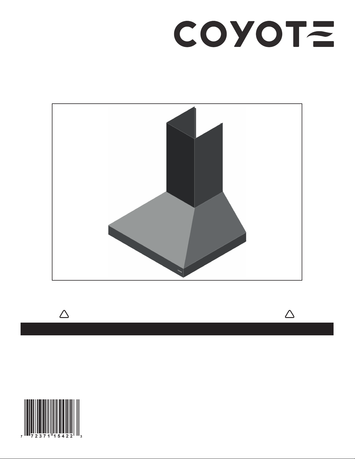
Coyote C1HOOD Series User manual
HB0304
23643 rev. 01
C1HOOD SERIES INSTALLATION INSTRUCTIONS
INTENDED FOR OUTDOOR DOMESTIC COOKING ONLY
INSTALLER: LEAVE THIS MANUAL WITH HOMEOWNER.
HOMEOWNER: USE AND CARE INFORMATION ON PAGES 8 AND 9.
READ AND SAVE THESE INSTRUCTIONS
COYOTE OUTDOOR LIVING, INC.
www.coyoteoutdoor.com
! !

2
TO REDUCE THE RISK OF FIRE, ELECTRIC SHOCK OR
INJURY TO PERSONS, OBSERVE THE FOLLOWING:
1. Use this unit only in the manner intended by the manufacturer. If
you have questions, contact the manufacturer at the address or
telephone number listed in the warranty.
2. Before servicing or cleaning unit, switch power off at service panel
and lock service disconnecting means to prevent power from
being switched on accidentally. When the service disconnecting
means cannot be locked, securely fasten a prominent warning
device, such as a tag, to the service panel.
3. Installation work and electrical wiring must be done by qualified
personnel in accordance with all applicable codes and standards,
including fire-rated construction codes and standards.
4. Sufficient air is needed for proper combustion and exhausting of
gases through the flue (chimney) of fuel burning equipment to
prevent backdrafting. Follow the heating equipment manufacturer’s
guidelines and safety standards such as those published by the
National Fire Protection Association (NFPA) and the American
Society for Heating, Refrigeration and Air Conditioning Engineers
(ASHRAE) and the local code authorities.
5. When cutting or drilling into wall or ceiling, do not damage
electrical wiring and other hidden utilities.
6. Ducted fans must always be vented to the outdoors.
7. Do not use this unit with any solid-state speed control device.
8. To reduce the risk of fire, use only metal ductwork.
9. This unit must be grounded and protected by a GFCI.
10. Suitable for use in damp locations only when installed in a GFCI-
protected branch-circuit.
11. This unit is not designed to be used with a charcoal grill.
12. When applicable local regulations comprise more restrictive
installation and/or certification requirements, the aforementioned
requirements prevail on those of this document and the installer
agrees to conform to these at his own expense.
TO REDUCETHE RISK OFA RANGETOP GREASE FIRE:
a) Never leave surface units unattended at high settings. Boilovers
cause smoking and greasy spillovers that may ignite. Heat oils
slowly on low or medium settings.
b) Always turn the range hood ON when cooking at high heat or
when flambeing food (i.e.: Crêpes Suzette, Cherries Jubilee,
Peppercorn Beef Flambé).
c) Clean ventilating fans frequently. Grease should not be allowed to
accumulate on fan, filters or in exhaust ducts.
d) Use proper pan size. Always use cookware appropriate for the
size of the surface element.
1. For general ventilating use only. Do not use to exhaust hazardous
or explosive materials and vapors.
2. To avoid motor bearing damage and noisy and/or unbalanced
impellers, keep drywall spray, construction dust, etc. off the hood.
3. Your hood has a thermal overload which will automatically shut off
the motor if it becomes overheated. The motor will restart when it
cools down. If the motor continues to shut off and restart, have the
hood serviced.
4. The hood must be installed at least 36” above the cooking surface.
5. Two installers are recommended because of the large size and
weight of this unit.
6. To reduce the risk of fire and to properly exhaust air, be sure to
duct air outside — Do not exhaust air into spaces within walls or
ceiling or into attics, crawl space or garage.
7. This product is equipped with a thermostat which may start blower
automatically. To reduce the risk of injury and to prevent power
from being switched on accidentally, switch power off at service
panel and lock or tag service panel.
8. To reduce the risk of fire and electrical shock, the C1HOOD
Series models should only be installed with the C1BLOW1200
INTERNAL BLOWER. Other blowers cannot be substituted.
9. Please read specification label on product for further information
and requirements.
WARNING
! CAUTION
TO REDUCETHE RISK OF INJURY TO PERSONS INTHE
EVENT OF A RANGE TOP GREASE FIRE, OBSERVE
THE FOLLOWING*:
1. SMOTHER FLAMES with a close-fitting lid, cookie sheet or metal
tray, then turn off the burner.BE CAREFUL TO PREVENT BURNS.
IF THE FLAMES DO NOT GO OUT IMMEDIATELY, EVACUATE
AND CALL THE FIRE DEPARTMENT.
2. NEVER PICK UP A FLAMING PAN — You may be burned.
3. DO NOT USE WATER, including wet dishcloths or towels — This
could cause a violent steam explosion.
4. Use an extinguisher ONLY if:
A. You own a Class ABC extinguisher and you know how to
operate it.
B. The fire is small and contained in the area where it started.
C. The fire department has been called.
D. You can fight the fire with your back to an exit.
* Based on “Kitchen Fire Safety Tips” published by NFPA.
WARNING
!
3
Make sure that the following items are included:
- Hood
- Hood mounting bracket (taped inside the hood)
- 10” round adapter (taped inside the hood)
- Installation manual
- Bag of parts including: 1 wire clamp, 3 waterproof wire connectors, 14 no. 10-12 x 2½” screws, 4 no. 8-18 x 3/8” screws, 10 washers,
1suction cup (contains more parts than required to perform the installation). (Taped inside the hood.)
Parts sold separately:
- Blower assembly model C1BLOW1200
- Decorative flue:
- Part no. C1FLUE8 for ceilings 8' to 8.5' high
- Part no. C1FLUE10 for ceilings 8.5' to 9.5' high
- Part no. C1FLUE12 for ceilings 9.5' to 12' high
These range hoods must be installed with the C1BLOW1200 blower (sold separately). Do not substitute for an other blower.
Plan where and how the ductwork will be installed. A straight, short duct run will allow the hood to perform most efficiently. Refer to
illustrations below to locate duct opening.
Install 10-inch ductwork, elbows (if needed) and roof or wall cap. Connect metal ductwork to the cap and work back towards the hood
location. Use 2" metal foil duct tape to seal the joints.
Run 3-wire power supply cable to installation location.
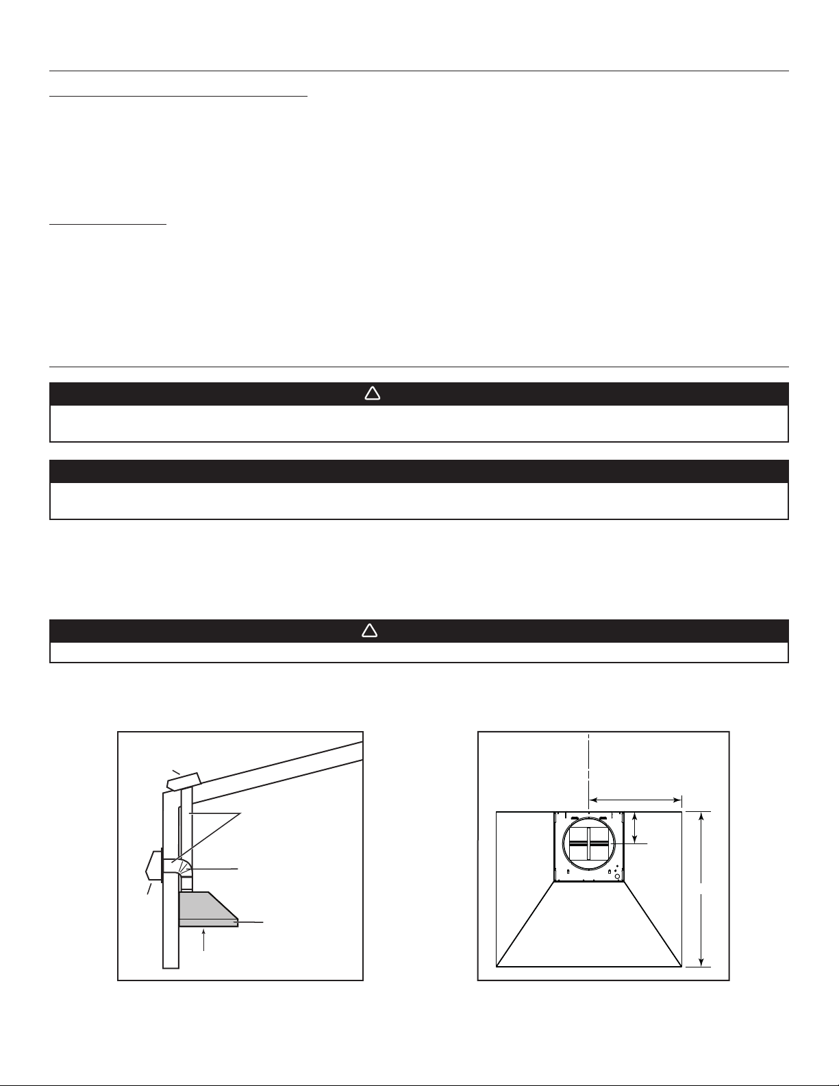
The hood must be installed at least 36’’ above the cooking surface.
HH0275A
HOOD
ROOF CAP
WALL
CAP
10” ROUND DUCT
36” ABOVE COOKING SURFACE
10” ROUND ELBOW
WARNING
!
The power cable must be a GFCI protected branch circuit.
WARNING
!
When performing installation, servicing or cleaning the unit, it is recommended to wear safety glasses and gloves.
This range hood is not designed for use with a charcoal grill.
CAUTION
This range hood is intended for outdoor covered patio or lanai area. As with all electric appliances, this unit must
be protected from the effects of weather.
HK0282A
30”
17 15/16” (36” hood)
20 15/16” (42” hood)
23 15/16” (48” hood)
6 1/4”
C
L
1. PREPARE THE INSTALLATION
2. INSTALL THE DUCTWORK AND ELECTRICAL WIRING

4
3. REMOVE THE GREASE FILTERS
Rest the range hood on a protected surface and remove the tape from the filters. Remove the filters from the range hood by pushing them
towards the nose of the hood and rotate downwards. Remove the parts bag, the adapter ring and the hood mounting bracket from inside
the hood and set these parts aside.
4. REMOVE THE WIRING COVER AND THE BLOWER PLATE
Using a Philips no. 2 screwdriver, remove the 3 retaining
screws (circled in illustration below) holding the wiring
cover inside the hood. Set aside the cover and its screws.
5. INSTALL THE ADAPTER AND THE WIRE CLAMP
Install the 10-inch round adapter on the top of the hood using 2 no. 8-18 x 3/8” Phillips screws.
NOTE: Use the smaller notches around the adapter.
Install the wire clamp (as shown in the inset on illustration at right).
HJ0186
HD1086
Using a 3/8” nutdriver, remove 2 nuts retaining the blower
plate to the inner top of the hood, set the plate and nuts
aside.
HD1079
HD1085
5
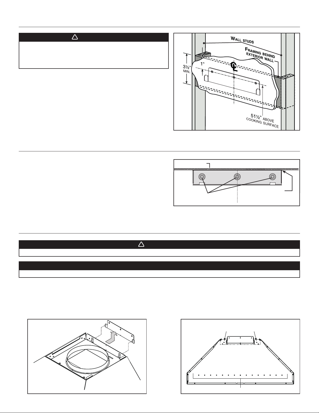
1. Align the hood and center it above the hood mounting bracket. Gently lower the hood until it securely engages the bracket.
2. Level the hood.
3. While the hood is hanging in place, secure it to the wall through both holes located in the upper back of hood
using 2 no. 10-12 x 2½” screws and washers. If required, pre-drill holes before securing the screws.
4. Using at least 1 hole on each side of the lower back of the hood, secure the hood into solid material (wall studs)
using 2 no. 10-12 x 2½” screws and washers. If required, pre-drill holes before securing the screws.
6. INSTALL HOOD MOUNTING BRACKET
If necessary, construct a wall framing using minimum 2” x 4” lumber. Proper
structural support is required to accomodate the weight of the hood.
After the wall surface is finished, measure and mark the center of the
installation; draw the vertical center line up to the ceiling.
Carefully center and level the hood mounting bracket over the installation
location. Secure it to the wall framing using 3 no. 10-12 x 2½” screws.
7. INSTALL UPPER FLUE MOUNTING BRACKET
8. INSTALL THE HOOD
WARNING
!
When cutting or drilling into wall, do not damage electrical
wiring and other hidden utilities.
Ensure that the wall is solid enough to withstand the weight
of the hood.
NOTE: The upper flue mounting bracket is packed with the decorative
flue, but the mounting bracket screws are in the parts bag of
the hood.
Center the upper flue mounting bracket with the center line drawn in the
previous step and place it flush with the ceiling.
Use the upper flue mounting bracket as a template to mark the position of
the screws.
Secure the upper flue bracket to the wall using 3 no. 10-12 x 2½” screws.
Ensure that the bracket is tight against the wall.
CAUTION
DO NOT REMOVE the protective plastic film covering the decorative flue (upper & lower) yet.
HD1084A LOWER HOLES LOCATION
UPPER HOLES LOCATION
RANGE HOOD BACK VIEW
HD1083A
SCREW LOCATIONS
HD0377
C
L
CEILING
MOUNTING BRACKET
FLUSH WITH CEILING
WARNING
!
BE CAREFUL when installing the decorative flue and hood, they may have sharp edges.
HD1087

6
Insert the house wiring cable through the wire clamp, and tighten the wire clamp
to secure the cable. Connect the power cable to the range hood wires using
provided waterproof wire connectors. Connect BLACK to BLACK, WHITE to
WHITE and GREEN or bare wire under GREEN ground screw. DO NOT FORGET
TO CONNECT THE GROUND.
WARNING
!
Risk of electric shock. Electrical wiring must be done by qualified personnel in accordance with all applicable
codes and standards. Before connecting wires, switch power off at service panel and lock service disconnecting
means to prevent power from being switched on accidentally.
WATERPROOF WIRE CONNECTORS INSTRUCTIONS:
1. Strip wires 3/8".
2. Align frayed strands or conductors.
3. Do not pre-twist. Place stripped wires together with ends even, but lead
smaller stranded wires slightly ahead of larger solid or stranded wire.
4. Twist connector onto wires pushing firmly until hand-tight. DO NOT over
torque.
5. When inserting wires into connectors, some sealant may leak out. Wipe off
excess sealant in and around conductors. DO NOT REUSE.
9. CONNECT THE WIRING
10. INSTALL THE BLOWER IN THE HOOD
Take the blower plate previously removed in step 4 and lay it on a protected surface.
Mount both blowers on the blower plate using 8 hexagonal nuts included with the blowers
(see illustration A). Make sure that both holes in the blower plate are entirely covered by the
blowers.The blowers should be 0.5 inch apart (see illustration B).
Reinstall the blower plate with blowers inside the hood by insert the blower plate tabs into
the slots and secure using both nuts previously removed in step 4 (see illustration C; blowers
not shown to ease understanding). Connect the blower power cord to the hood, and tie the
blower power cord using the preinstalled twist tie.
HD1075
CAUTION
When reinstalling the wiring box cover, carefully insert the screws
by hand, then use a screwdriver to prevent stripping.
Reinstall wiring box cover, making sure not to pinch wires. HE0338
GROUND SCREW
HO0343
A
C
HD1068A
0.5"
B C
7
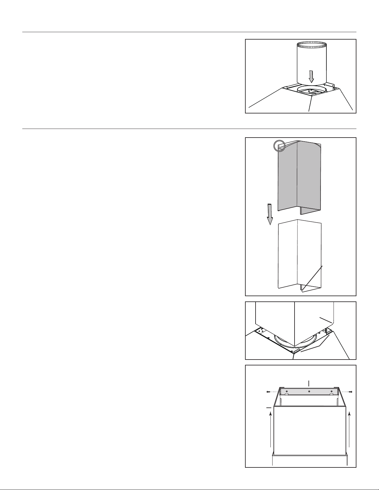
11. DUCT CONNECTION
Slide a 10” metal round duct over the adapter ring on top of the hood. Use metal foil duct
tape to seal the joint.
HJ0187
12. PREPARE AND INSTALL THE DECORATIVE FLUE
HO0341
LOWER FLUE
REAR NOTCH
Remove the protective plastic film covering the lower flue only.
Peel off both corners at the top of the upper flue.
Position the lower flue rear notches down (the ones with the 45° angle).
Gently slide the upper flue inside the lower flue, making sure the holes are on the top, so
the upper flue can be screwed to the flue mounting bracket.
Carefully slide in place the decorative flues (notches end first) between the shaded parts
and the exterior wall of the top of the hood.
Slide up the upper flue until it is aligned with its mounting bracket. The bracket must be
inside the flue. Secure it to the bracket using 2 no. 8 x 3/8” screws (from hood parts bag).
NOTE: Duct not shown in illustration to ease understanding.
Remove the protective plastic film covering the upper flue.
HO0140
UPPER FLUE MOUNTING BRACKET
FRONT VIEW
UPPER
FLUE
HO0342
LOWER FLUE
REAR NOTCH
SHADED
PARTS
8
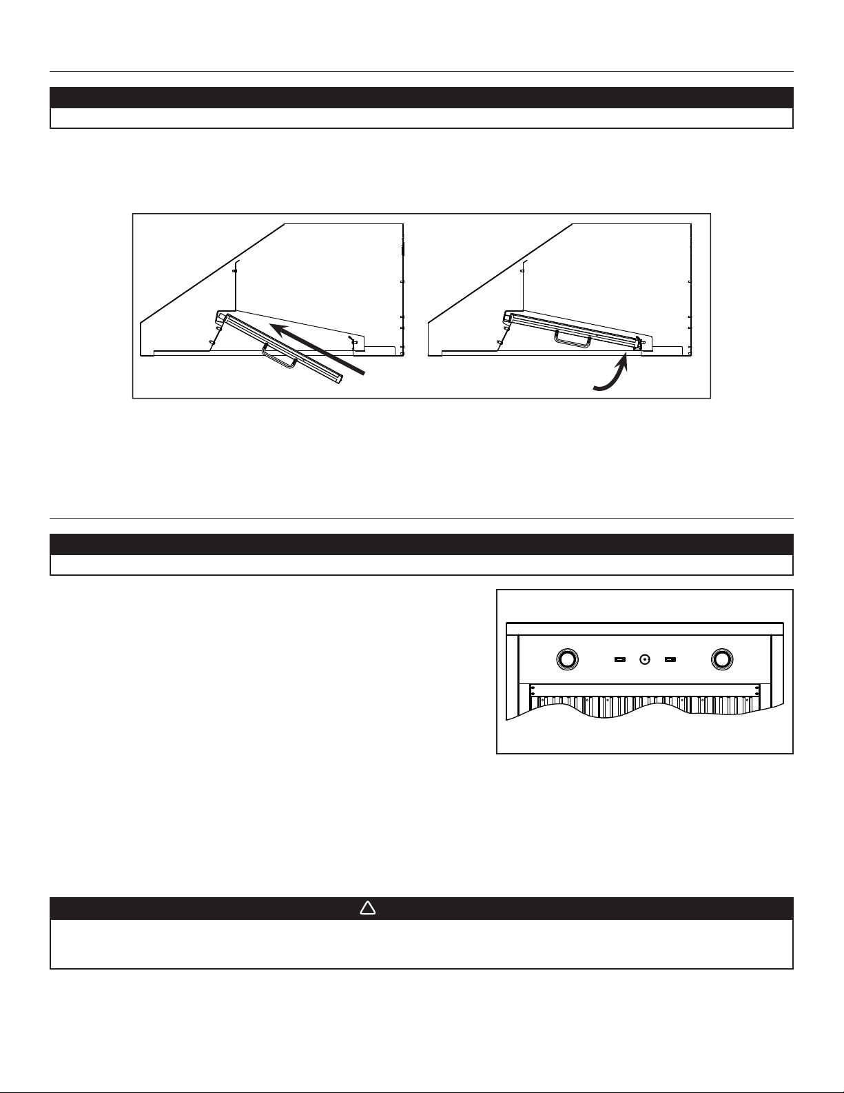
13. REINSTALL THE FILTERS
CAUTION
Remove the protective plastic film covering the filters before installing them.
It is recommended to install side filters first and to finish with center one(s).
1. Insert the end of the filter with the spring into the front channel of the hood.
2. Raise the other end toward the inside of the hood and insert in the grease drip rail.
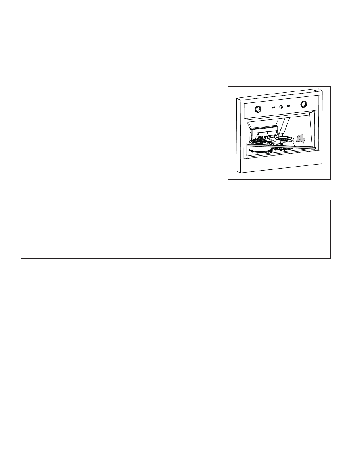
14. OPERATION
BLOWER
The blower is operated using two controls.
Use the ON/OFF rocker switch (1) to start and stop the blower. When turned ON,
the switch turns red and the blower operates at the speed set by the speed control
knob (2).
Turn the speed control knob counterclockwise to increase blower speed – clockwise
to decrease speed.
COOKTOP LIGHTING (HALOGEN)
Use the ON/OFF rocker switch (3) to turn the halogen lights ON or OFF.
1 2 3
HC0087
1) ON/OFF blower switch
2) Blower speed control knob
3) Halogen light switch
HEAT SENTRY™
This hood is equipped with a Heat Sentry™ thermostat. This thermostat is a device that will turn on the blower to high speed if it senses
excessive heat above the cooking surface.
1) If blower is OFF - it turns blower ON to high speed.
2) If blower is already ON - it sets blower on high speed.
When the temperature drops to normal, the blower will return to its original setting.
WARNING
!
The HEAT SENTRY can start the blower during a range top fire or other excessive heat situations even if the hood
is turned off. In this case, it is impossible to turn the blower OFF using control panel switch. To stop the blower,
disconnect blower cord plug.
HD1078
CAUTION
Before using the range hood, remove the remaining protective plastic film covering the hood surfaces.
9
15. USE AND CARE
Baffle Filters
The baffle filters should be cleaned frequently. Use a warm detergent solution. Wash more often if your cooking style generates greater
grease — like frying foods or wok cooking.
Remove the filters from the range hood by pushing them towards the nose of the hood and rotate downwards. Baffle filters are dishwasher
safe. Allow filters to dry completely before reinstalling them in the hood.
Clean all-metal filters in the dishwasher using a non-phosphate detergent. Discoloration of the filters may occur if using phosphate
detergent or as a result of local water conditions — but this will not affect filter performance. This discoloration is not covered by the
warranty.
Grease Drip Rail
The grease drip rail should be cleaned frequently. To remove, rotate the grease rail to
disengage it from the bottom panel, then slide it away in a diagonal movement. Wash in a
a warm detergent solution. As with the baffle filters, wash more often if your cooking style
generates greater grease — like frying foods or wok cooking. Allow the grease drip rail to
dry completely before reinstalling it in the hood.
General cleaning instructions
Stainless steel cleaning:
Avoid when choosing a detergent:
- Any cleaners that contain bleach will attack stainless steel.
- Any products containing: chloride, fluoride, iodide, bromide will deteriorate surfaces rapidly.
- Any combustible products used for cleaning such as acetone, alcohol, ether, benzol, etc., are highly explosive and should never be
used close to a range.
Do:
• Regularly wash with clean cloth or rag soaked with warm water
and mild soap or liquid dish detergent.
• Always clean in the direction of original polish lines.
• Always rinse well with clear water (2 or 3 times) after cleaning.
Wipe dry completely.
• You may also use a specialized household stainless steel
cleaner.
Don’t:
• Use any steel or stainless steel wool or any other scrapers to
remove stubborn dirt.
• Use any harsh or abrasive cleansers.
• Allow dirt to accumulate.
• Let plaster dust or any other construction residues reach the
range hood. During construction/renovation, cover the range
hood to make sure no dust sticks to stainless steel surface.
HD1088
10
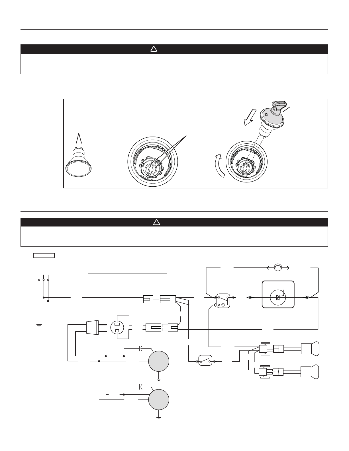
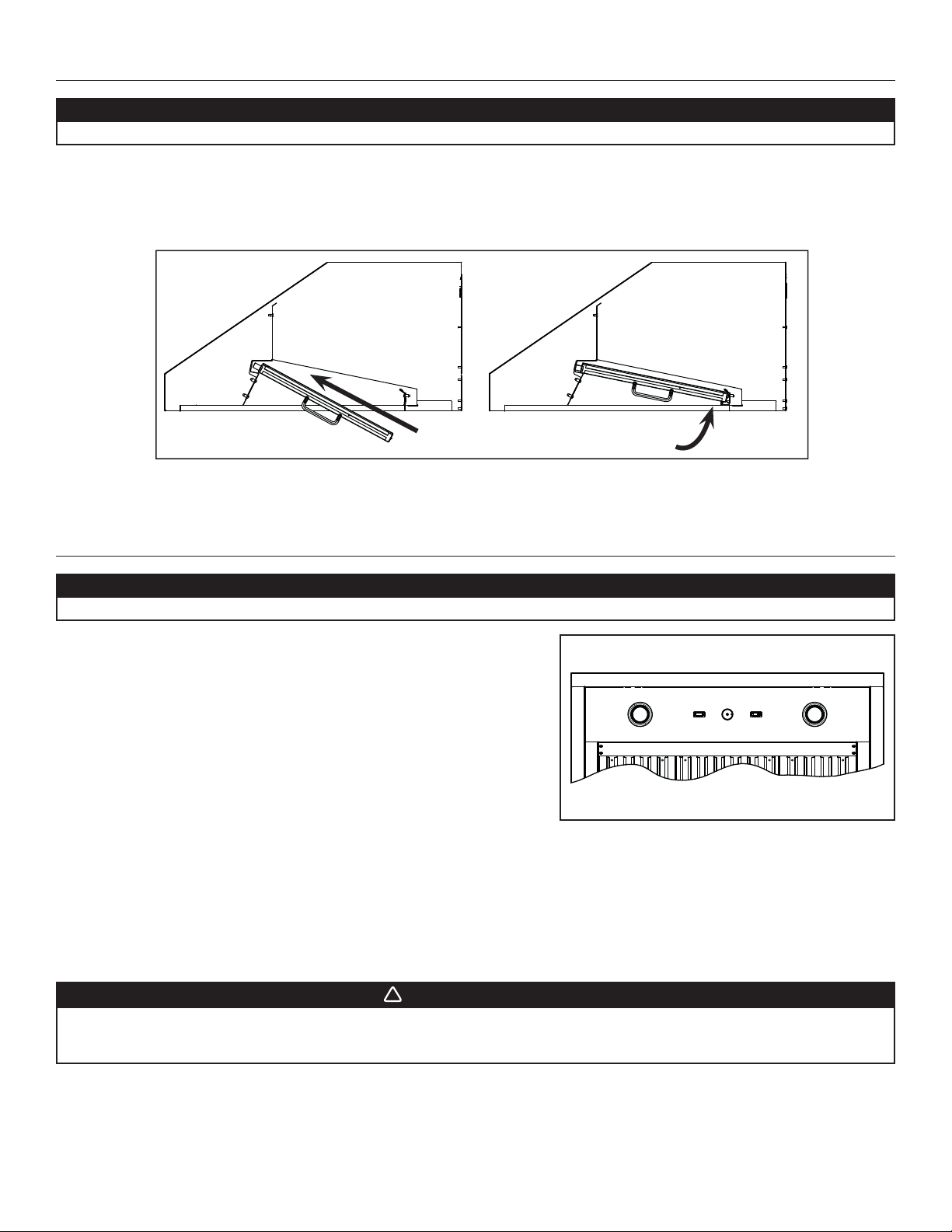
17. WIRING DIAGRAM
This hood is equiped with two 120 V, 50 W, MR16 with GU10 base, shielded halogen bulbs.
To remove the bulbs, press suction cup tool (included in parts bag) on bulb and rotate counterclockwise to disengage the bulb leads from
their grooves.
Install the new bulbs by placing the bulb leads into their grooves in the socket. Gently push upwards and turn clockwise until secure.
WARNING
!
Do not touch lamps during or soon after operation. Burns may occur. In order to prevent the risk of personal injury,
only install shielded halogen lamps. Also, never install a cool beam, a dichroic lamp, a lamp not suitable for use in
recessed luminaires or identified for use in enclosed fixtures.
HR0212
16. LIGHT BULBS REPLACEMENT
M
M
Neutral
Line
Ground
120 V AC
Lamp
Lamp switch
HS
THERMOSTAT
BLK
RED RED
BLK
BLK
WHT
Fan switch
SPEED CONTROL
WHT
BLK
YEL
WHT
WHT
BLK
BLK WHT
BLK
Lamp
WHT
YEL
WHT
BLK WHT
COLOR CODE
BLK
RED
BLACK
RED
WHT
YEL
WHITE
YELLOW
REF: 70103_REV-A
HE0337A
BLK
WHT
WARNING
!
Risk of electrical shock. Electrical wiring must be done by qualified personnel in accordance with all applicable
codes and standards. Before connecting wires, switch power off at service panel and lock service disconnecting
means to prevent power from being switched on accidentally.
BULB LEADS
BULB LEAD GROOVES
(IN SOCKET)
SUCTION CUP TOOL

11
18. SERVICE PARTS
REPLACEMENT PARTS AND REPAIRS
In order to ensure your unit remains in good working
condition, you must use Coyote Outdoor Living Inc.
genuine replacement parts only. Coyote Outdoor Living
Inc. genuine replacement parts are specially designed
for each unit and are manufactured to comply with all
the applicable certification standards and maintain a
high standard of safety. Any third party replacement
part used may cause serious damage and drastically
reduce the performance level of your unit, which will
result in premature failing. Coyote Outdoor Living
Inc. recommends to contact our Customer Service
Department at 855-520-1559 for all replacement parts
and service questions.
B
C
D
E
F
G
H
I
K
L
N
M
J
HL0432
KEY NO. PART NO. DESCRIPTION QUANTITY
36" 42" 48"
1 C1FLUE8* DECORATIVE FLUE KIT - 8 TO 8.5-FT HIGH CEILING 111
1 C1FLUE10* DECORATIVE FLUE KIT - 8.5 TO 9.5-FT HIGH CEILING 111
1 C1FLUE12* DECORATIVE FLUE KIT - 9.5 TO 12-FT HIGH CEILING 111
2 SV08541 10” ROUND ADAPTER 111
3 SV16569 LIGHT SOCKET AND TRIM ASSEMBLY 222
4 SV05921 GU10 HALOGEN BULB 222
5 SV03435 HEAT SENTRY™ THERMOSTAT 111
6 SV02563 LIGHT ROCKER SWITCH 111
7 C1BLOW1200** BLOWER ASSEMBLY 111
8SV60675 BAFFLE FILTER WITH FILTER SPRING 11.84” X15.125” 1 3 2
SV60716 BAFFLE FILTER WITH FILTER SPRING 8.84” X15.125” 2 0 2
9 SV08337 SPRINGS FOR BAFFLE FILTERS (SET OF 6) 1 1 1
10
SV65734 GREASE RAIL FOR 36-IN.-WIDE HOOD 100
SV65735 GREASE RAIL FOR 42-IN.-WIDE HOOD 010
SV65736 GREASE RAIL FOR 48-IN.-WIDE HOOD 001
11 SV03503 BLOWER ROCKER SWITCH 111
12 SV08549 BLOWER SPEED CONTROL KNOB 111
13 SV03501 BLOWER SPEED CONTROL 111
*** SV23320 PARTS BAG: 1 WIRE CLAMP, 3 WATERPROOF WIRE CONNECTORS,
14 NO. 10-12 X2½” SCREWS, 4 NO. 8-18 X3/8” SCREWS, 10WASHERS, 1SUCTION CUP.111
* OPTIONAL PART, SOLD SEPARATELY
** PART SOLD SEPARATELY
*** NOT SHOWN

12
19. WARRANTY
TO THE MAXIMUM EXTENT PERMITTED BY LAW, THIS LIMITED WARRANTY AND THE REMEDIES SET FORTH BELOW ARE
EXCLUSIVE AND IN LIEU OF ALL OTHER WARRANTIES, REMEDIES AND CONDITIONS, WHETHER ORAL OR WRITTEN, EXPRESS
OR IMPLIED.TO THE MAXIMUM EXTENT PERMITTED BY LAW, COYOTE OUTDOOR LIVING, INC.ALSO SPECIFICALLY DISCLAIMS
ANY AND ALL IMPLIED WARRANTIES, INCLUDING, WITHOUT LIMITATION, WARRANTIES OF MERCHANTABILITY AND FITNESS
FOR A PARTICULAR PURPOSE.
Coyote Outdoor Living, Inc. issues this limited warranty to the original purchaser at the original site of delivery with proof of purchase
and specifically warrants that the Outdoor Ventilation Hood or Liner, when subject to normal residential use, will be free from defects
in workmanship and materials for one year from the date of original purchase. This limited warranty is not transferable and specifically
excludes any ventilation product used in a commercial setting, where anyone other than the original purchaser (homeowner) would be
using and maintaining the product. This limited warranty specifically excludes all issues that may arise from surface corrosion, scratches,
and discoloration during regular use. It also does not extend to fluorescent lamp starters, tubes, halogen and incandescent bulbs, fuses,
filters, ducts, roof caps, wall caps and other accessories for ducting. This limited warranty does NOT COVER LABOR OR LABOR
RELATED CHARGES and there will be shipping and handling charges for the delivery of any needed part(s).
Coyote Outdoor Living, Inc.’s obligation under this limited warranty is limited solely to repair or replacement, at our option, of the pertinent
component during the warranty period, and the extent of any liability of Coyote Outdoor Living, Inc. under this warranty is limited to repair
or replacement. This limited warranty does not cover normal wear of parts or damage resulting from any of the following: negligent use
or misuse of the product, improper maintenance or repair, faulty installation, use contrary to operating instructions, or alteration by any
person other than a factory service center. The above warranty periods are not extended by any repair or replacement.
WARRANTY CLAIM PROCEDURE: If you require service or parts for your Coyote Grill, please contact our Warranty Service Center for
factory direct assistance. Our hours of operation are 8 am to 4:30 pm CST. The phone number is 855.520.1559 and the email address is
support@coyoteoutdoor.com. You may also fill out warranty claims online at www.coyoteoutdoor.com. Please have your model number,
serial number and proof of purchase available for any warranty claim.
Coyote Outdoor Living, Inc. may require the return of defective parts for examination before issuing replacement parts. If you are required
to return defective parts, shipping charges must be prepaid by the customer. Upon examination and to Coyote Outdoors determination,
if the original part is proven defective, Coyote Outdoor may approve your claim and elect to replace such parts without charge. In every
instance, the customer is responsible for shipping and handling of replacement parts. Component repair or replacement is the exclusive
remedy under this limited warranty and Coyote Outdoor shall not be liable for any incidental or consequential damages.
This limited warranty does not cover any failures or operating difficulties due to accidents, abuse, misuse, alteration, misapplication,
vandalism, improper installation, maintenance or service, or damages caused by flashback fire or grease fire. This limited warranty does
not cover scratches, dents, corrosion or discoloration caused by weather, heat, abrasive and chemical cleaners, pool or spa chemicals,
and/or any tools used in the assembly or installation of this unit. This limited warranty does not cover paint loss, surface rust, corrosion or
stainless steel discoloration which is considered normal wear and tear.This limited warranty does not cover the cost of any inconvenience,
personal injury, or property damage due to improper use or product failure. Deterioration or damage due to severe weather conditions
such as hail, hurricanes, earthquakes, tsunamis, tornadoes, terrorism, discoloration due to exposure to chemicals either directly or in the
atmosphere, Acts of God/forces of Nature are not covered by this limited warranty.

HB0304
23643 rév. 01
INSTRUCTIONS D'INSTALLATION
DES HOTTES DE SÉRIE C1HOOD
CONÇUES UNIQUEMENT POUR LA CUISSON DOMESTIQUE EXTÉRIEURE
INSTALLATEUR : LAISSER CE GUIDE AU PROPRIÉTAIRE.
PROPRIÉTAIRE : DIRECTIVES D’UTILISATION ET D’ENTRETIEN EN PAGES 8 ET 9.
LIRE ET CONSERVER CES DIRECTIVES
COYOTE OUTDOOR LIVING, INC.
www.coyoteoutdoor.com
! !

2
AFIN DE RÉDUIRE LES RISQUES D’INCENDIE,
D’ÉLECTROCUTION OU DE BLESSURES
CORPORELLES, SUIVEZ LES DIRECTIVES
SUIVANTES :
1. N’utilisez cet appareil que de la façon prévue par le
manufacturier. Si vous avez des questions, contactez le
manufacturier à l’adresse ou au numéro de téléphone indiqués
dans la garantie.
2. Avant de réparer ou de nettoyer l’appareil, couper l’alimentation
électrique en verrouillant le panneau de distribution afin
d’éviter sa remise en marche accidentelle. Si le panneau de
distribution ne peut être verrouillé, y fixer un avertissement en
évidence, telle qu’une étiquette de couleur vive.
3. Les travaux d’installation et de raccordement électrique doivent
être effectués par une personne qualifiée, conformément
aux codes et aux standards de construction, incluant ceux
concernant la protection contre les incendies.
4. Une quantité d’air adéquate est requise afin d’assurer une
bonne combustion et l’évacuation des gaz par la cheminée
dans le cas des équipements alimentés au gaz afin de prévenir
les retours de cheminée. Conformez-vous aux instructions et
aux standards de sécurité des manufacturiers d’équipement de
chauffage, tel qu’ils sont publiés par la National Fire Protection
Association (NFPA) et l’American Society for Heating,
Refrigeration and Air Conditioning Engineers (ASHRAE) ainsi
que les responsables des codes locaux.
5. Veillez à ne pas endommager le câblage électrique ou d’autres
équipements non apparents lors de la découpe ou du perçage
du mur ou du plafond.
6. Les ventilateurs avec conduits doivent toujours évacuer l’air
à l’extérieur.
7. Ne pas utiliser cet appareil avec une commande de vitesse à
semi-conducteur additionnelle.
8. Afinderéduirelesrisquesd’incendie,n’utilisezquedes conduits
de métal.
9. Cet appareil doit être mis à la terre et protégé par un DDFT
(disjoncteur de fuite à la terre).
10.Convient à une utilisation dans des lieux humides seulement
lorsqu’elle est raccordée à un DISJONCTEUR DE FUITE À LA
TERRE (DDFT).
11. Cet appareil n’est pas conçu pour être utilisé avec un barbecue
au charbon de bois.
12.Lorsqu’une réglementation est en vigueur et qu’elle comporte
des exigences d’installation et/ou de certification plus
restrictives, lesdites exigences prévalent sur celles de ce
document et l’installateur entend s’y conformer à ses frais.
AFIN DE RÉDUIRE LES RISQUES DE FEU
DE CUISINIÈRE :
a) Ne jamais laisser les appareils de cuisson sans surveillance
lorsqu’ils sont réglés à feu vif. Les débordements engendrent
de la fumée et des déversements graisseux pouvant
s’enflammer. Chauffez l’huile lentement, à feu doux ou moyen.
b) Mettez toujours la hotte en marche lorsque vous cuisinez à feu
vif ou que vous cuisinez des mets flambés (par ex. : crêpes
Suzette, cerises jubilé, steaks au poivre flambés).
c) Nettoyez régulièrement le ventilateur.Ne laissez pas la graisse
s’accumuler sur le ventilateur, les filtres ou les conduits
d’évacuation.
d) Utilisez le bon format de casserole. Servez-vous toujours de
casseroles et d’ustensiles appropriés à la dimension de la
surface chauffante.
1. Pourusagedomestique seulement.Ne pasutiliserpour évacuer
des vapeurs ou des matières dangereuses ou explosives.
2. Afin d’éviter tout dommage au moteur et de débalancer ou de
rendre bruyantes les roues de moteurs, garder votre appareil à
l’abri des poussières de gypse et de construction/rénovation, etc.
3. Le moteur de votre hotte possède une protection thermique
qui arrêtera automatiquement le fonctionnement du moteur s’il
surchauffe. Le moteur redémarrera automatiquement une fois
refroidi. Si le moteur continue à arrêter et à redémarrer, faites-
le vérifier.
4. Le bas de votre hotte doit être situé à un minimum de 36 po
au-dessus de la table de cuisson.
5. Deux installateurs sont recommandés lors de l’installation vu
la grande dimension et le poids de cette hotte.
6. Afin de réduire les risques d’incendie, assurez-vous d’évacuer
l’air à l’extérieur. Ne pas évacuer l’air dans des espaces
restreints comme l’intérieur des murs ou plafond ou dans le
grenier, faux plafond ou garage.
7. Cet appareil est équipé d’un thermostat pouvant faire démarrer
le ventilateur automatiquement. Afin de réduire le risque de
blessure, couper le courant à partir du panneau électrique et le
verrouiller ou apposer un avertissement sur le panneau afin de
prévenir que la hotte ne soit mise en marche accidentellement.
8. Afin de réduire les risques d’incendie et d’électrocution, la hotte
Coyote de série C1HOOD ne doit être installée uniquement
qu'avec le ventilateur interne C1BLOW1200. Aucun autre
ventilateur ne doit être utilisé.
9. Veuillez consulter l’autocollant apposé à l’intérieur de la hotte
pour plus d’information ou autres exigences.
AVERTISSEMENT
!
ATTENTION
AVERTISSEMENT
!
AFIN D’ÉVITER TOUT RISQUE DE BLESSURES LORS
D’UN FEU DE CUISINIÈRE, SUIVEZ CES DIRECTIVES* :
1. Étouffez les flammes avec un couvercle hermétique,
une tôle à biscuits ou un plateau métallique et ensuite,
éteindre le brûleur. PRENEZ SOIN D’ÉVITER LES
BRÛLURES. SI LES FLAMMES NE S’ÉTEIGNENT PAS
IMMÉDIATEMENT, ÉVACUEZ LES LIEUX ET APPELEZ
LES POMPIERS.
2. NE PRENEZ JAMAIS UNE CASSEROLE EN FLAMMES
DANS VOS MAINS. Vous pourriez vous brûler.
3. N’UTILISEZ PAS D’EAU, incluant un linge à vaisselle ou une
serviette mouillée, cela pourrait occasionner une violente
explosion de vapeur.
4. N’utilisez un extincteur QUE DANS LE CAS OÙ :
A. Vous savez qu’il s’agit d’un extincteur de classe ABC et
que vous en connaissez le fonctionnement.
B. L’incendie est petit et limité à l’endroit où il a débuté.
C. Les pompiers ont été avisés.
D. Vous pouvez combattre l’incendie en ayant accès à une
sortie de secours.
*Tirées du Kitchen Fire Safety Tips publié par la NFPA.

3
NOTE: Avant de commencer l'installation, vérifier le contenu de la boîte. Si des pièces sont manquantes ou endommagées, contacter le
manufacturier.
S'assurer que les articles suivants sont inclus:
- Hotte
- Accessoires • Support de montage de la hotte (fixé avec du ruban adhésif à l'intérieur de la hotte)
• Adaptateur de 10 po rond (fixé avec du ruban adhésif à l'intérieur de la hotte)
• Guide d'installation
• Sac de pièces comprenant : 3 capuchons de connexion étanches, 1 serre-fils, 14 vis n° 10-12 x 2½ po,
4 vis n° 8-18 x 3/8 po, 10 rondelles, 1ventouse (comprend plus de pièces que nécessaire pour l'installation)
(le sac est fixé avec du ruban adhésif à l'intérieur de la hotte).
Pièces vendues séparément:
- Ensemble ventilateur modèle C1BLOW1200
- Conduit décoratif:
- Pièce n° C1FLUE8 pour un plafond de 8 pi à 8,5 pi de hauteur
- Pièce n° C1FLUE10 pour un plafond de 8,5 pi à 9,5 pi de hauteur
- Pièce n° C1FLUE12 pour un plafond de 9,5 pi à 12 pi de hauteur.
AVERTISSEMENT
!
Il est recommandé de porter des lunettes et des gants de sécurité lors de l’installation, de l’entretien et de la
réparation de cet appareil. Cette hotte n'est pas conçue pour être utilisée avec un barbecue au charbon de bois.
Ces hottes doivent être installées avec le ventilateur C1BLOW1200 (vendu séparément). Ne pas utiliser d'autre ventilateur.
Déterminer à quel endroit et de quelle façon les conduits seront installés. Un conduit droit et court permettra à votre hotte de fonctionner
plus efficacement. Consulter les illustrations ci-dessous pour positionner l'ouverture pour le conduit.
Installer des conduits de 10 po rond, des coudes (si nécessaires) et un capuchon de toit ou de mur. Relier le conduit en métal au
capuchon, puis acheminer le conduit jusqu’à l’emplacement de la hotte. Sceller hermétiquement les raccords à l’aide de ruban adhésif
de métal de 2 po de largeur.
Acheminer un câble d’alimentation électrique à 3 conducteurs jusqu’à l’emplacement de la hotte.
La hotte doit être installée à au moins 36 po au-dessus de la surface de cuisson.
HH0275F
HOTTE
CAPUCHON DE TOIT
CAPUCHON
MURAL
CONDUIT ROND
DE 10 PO
36 PO AU-DESSUS DE LA
SURFACE DE CUISSON
COUDE ROND
DE 10 PO
AVERTISSEMENT
!
Le fil d’alimentation électrique doit être raccordé à un disjoncteur de fuite à la terre (DDFT).
ATTENTION
Cette hotte est conçue pour être utilisée sur un patio couvert ou une véranda. Comme tous les électroménagers,
cet appareil doit être à l’abri des intempéries.
HK0282F
30 po
17 15/16 po (hotte de 36 po)
20 15/16 po (hotte de 42 po)
23 15/16 po (hotte de 48 po)
6 1/4 po
C
L
1. PRÉPARER L'INSTALLATION
2. INSTALLER LES CONDUITS ET LE CÂBLAGE ÉLECTRIQUE

4
3. RETIRER LES FILTRES À GRAISSE
Déposer la hotte sur une surface protégée et retirer le ruban adhésif des filtres. Retirer les filtres en les poussant vers l'avant de la hotte et
en les basculant. Retirer le sac de pièces, l'adaptateur et le support de montage de la hotte de l'intérieur de celle-ci et mettre ces pièces
de côté.
HD1079
4. RETIRER LE COUVERCLE DU COMPARTIMENT ÉLECTRIQUE
ET LA PLAQUE VENTILATEUR
À l'aide d'un tournevis Philips n° 2, retirer les 3 vis
(encerclées dans l'illustration ci-dessous) retenant le
couvercle du compartiment électrique à l'intérieur de la
hotte. Mettre de côté le couvercle et ses vis.
5. INSTALLER L'ADAPTATEUR ET LE SERRE-FILS
Fixer l'adaptateur de 10 po rond sur le dessus de la hotte à l'aide de 2 vis Phillips n° 8-18 x 3/8 po.
NOTE: Utiliser les encoches les plus petites du pourtour de l'adaptateur.
Installer le serre-fils (tel qu'il est démontré dans le médaillon de l'illustration de droite).
HJ0186
HD1085 HD1086
À l'aide d'un tourne-écrou de 3/8 po, retirer les 2 écrous
retenant la plaque ventilateur au dessus interne de la
hotte, puis mettre la plaque et les écrous de côté.

5
1. Aligner la hotte et la centrer au-dessus de son support de montage. Abaisser doucement la hotte jusqu’à ce qu’elle s’accroche à
son support.
2. Mettre la hotte au niveau.
3. Une fois la hotte en place, fixer celle-ci au mur à travers les 2 trous situés au haut du dos de la hotte à l’aide de 2 vis n° 10-12 x 2½ po
et rondelles. Si nécessaire, pratiquer des avant-trous avant de visser les vis.
4. En utilisant au moins un trou de chaque côté du bas du dos de la hotte, fixer la hotte à un matériau solide (montants) à l'aide de 2 vis
n° 10-12 x 2½ po et rondelles. Si nécessaire, pratiquer des avant-trous avant de visser les vis.
6. INSTALLER LE SUPPORT DE MONTAGE DE LA HOTTE
Si nécessaire, construire un cadre mural en bois en utilisant un madrier
de 2 po x 4 po minimum. Un support structural adéquat est requis pour
supporter le poids de la hotte.
Après la finition du mur, mesurer et tracer le centre de l'installation; tirer
une ligne verticale jusqu'au plafond.
Centrer soigneusement le support au-dessus de l’emplacement de
l’installation et le mettre au niveau. Fixer le support de montage au cadre
mural à l’aide de 3 vis n° 10-12 x 2½ po.
7. INSTALLER LE SUPPORT DE MONTAGE DU CONDUIT DÉCORATIF SUPÉRIEUR
8. INSTALLER LA HOTTE
AVERTISSEMENT
!
Lorsde la découpeou du perçage dans unmur,veillezà nepas
endommager le câblage électrique ou d’autres équipements
non apparents.
S'assurer que le mur est assez solide pour supporter le
poids de la hotte.
NOTE: Le support de montage du conduit décoratif supérieur est
inclus dans la boîte du conduit décoratif, mais les vis du
support de montage sont dans le sac de pièces de la hotte.
Centrer le support de montage du conduit décoratif supérieur selon la ligne
tracée à l’étape précédente et le positionner au ras du plafond.
Utiliser le support de montage comme gabarit pour marquer la position
des vis.
Fixer au mur le support de montage du conduit supérieur à l’aide de 3 vis
n° 10-12 x 2½ po.
S’assurer que le support de montage est bien appuyé contre le mur.
ATTENTION
NE PAS RETIRER pour l’instant la pellicule de plastique protectrice recouvrant les conduits décoratifs.
HD1084F EMPLACEMENT DES TROUS INFÉRIEURS
EMPLACEMENT DES TROUS SUPÉRIEURS
VUE ARRIÈRE DE LA HOTTE
HD1083F
EMPLACEMENT DES VIS
HD0377
C
L
PLAFOND
SUPPORT DE MONTAGE
AU RAS DU PLAFOND
AVERTISSEMENT
!
SOYEZ PRUDENT lors de l’installation du conduit décoratif et de la hotte, il pourrait y avoir des arêtes vives.
HD1087

6
Passer le câble d'alimentation dans le serre-fils, puis serrer le serre-fils pour fixer
le câble. Brancher les fils de la hotte aux fils du câble d'alimentation à l'aide des
capuchons de connexions étanches fournis. Connecter le fil NOIR au NOIR, le fil
BLANC au BLANC et le fil VERT ou dénudé à la vis de mise à la terre. NE PAS
OUBLIER DE CONNECTER LA MISE À LA TERRE.
AVERTISSEMENT
!
Risque d’électrocution. Le branchement électrique doit être effectué par du personnel qualifié conformément aux
codes et aux standards en vigueur. Avant d’effectuer le branchement, coupez l’alimentation électrique au panneau
de distribution et verrouillez-le pour éviter une mise en marche accidentelle.
DIRECTIVES POUR L'UTILISATION DES CAPUCHONS DE CONNEXIONS ÉTANCHES :
1. Dégainer les fils d'une longueur de 3/8 po.
2. Égaliser les brins ou les conducteurs.
3. Ne pas les tordre. Rapprocher les fils et mettre leurs bouts égaux, sauf pour
les fils à brins plus petits, lesquels doivent dépasser légèrement des fils
plus gros.
4. Insérer les fils dans le capuchon de connexion en poussant légèrement et
tordre. NE PAS trop tordre.
5. Un peu de scellant pourrait s’échapper lors de l’insertion des fils dans le
capuchon de connexion.Essuyer l’excès de scellant autour des conducteurs.
NE PAS RÉUTILISER.
9. BRANCHEMENT ÉLECTRIQUE
10. INSTALLER LE VENTILATEUR DANS LA HOTTE
ATTENTION
Lors de la remise en place du couvercle du compartiment
électrique, insérer doucement les vis à la main, puis utiliser un
tournevis manuel pour éviter d'endommager les filets des vis.
Remettre en place le couvercle du compartiment électrique, en prenant garde
de ne pas pincer les fils.
HE0338
VIS DE MISE À
LA TERRE
Prendre la plaque ventilateur retirée à l'étape 4 et la déposer sur une surface protégée.
Assembler les deux ventilateurs sur la plaque à l'aide de 8 écrous hexagonaux inclus avec
les ventilateurs (voir l'illustration A). S'assurer que les deux trous de la plaque ventilateur sont
complètement couverts par les ventilateurs; les ventilateurs doivent être distants de 0 5 po
l'un de l'autre (voir l'illustration B).
Remettre en place la plaque ventilateur avec les ventilateurs dans la hotte en insérant
les pattes de la plaque dans les fentes et fixer la plaque à la hotte à l'aide des 2 écrous
retirés à l'étape 4 (voir l'illustration C; les ventilateurs ne sont pas illustrés afin de faciliter la
compréhension).
Brancher le cordon d'alimentation du ventilateur dans la hotte, puis attacher le câble
d'alimentation à l'aide de l'attache installée en usine.
HD1075
HO0343
A
C
HD1068F
0,5 po
B C

7
11. RACCORDEMENT DU CONDUIT
Glisser un conduit rond de 10 po en métal par-dessus l’adaptateur. Sceller hermétiquement
le joint à l’aide de ruban adhésif de métal.
HJ0187
12. PRÉPARER ET INSTALLER LE CONDUIT DÉCORATIF
HO0341
ENCOCHE
ARRIÈRE DU
CONDUIT
INFÉRIEUR
Ne retirer que la pellicule de plastique protectrice recouvrant le conduit décoratif inférieur
seulement.
N’enlever que juste assez de plastique protecteur pour dégager les coins supérieurs du
conduit décoratif supérieur.
Positionner les encoches arrière du conduit inférieur vers le bas (celles avec un angle
de 45°).
Glisser délicatement le conduit décoratif supérieur dans le conduit décoratif inférieur, en
s'assurant que les trous sont en haut, pour que le conduit décoratif supérieur puisse être
fixé à son support de montage.
Glisser délicatement en place le conduit décoratif (le côté des encoches en premier) entre
les pièces en gris et la paroi extérieure du dessus de la hotte (voir l’illustration ci-contre).
Soulever le conduit décoratif supérieur jusqu’au niveau de son support de montage. Ce
dernier doit être à l’intérieur du conduit. Fixer le conduit supérieur au support à l’aide des
2 vis n° 8 x 3/8 po (incluses dans le sac de pièces de la hotte).
NOTE: Conduit non montré dans l’illustration afin de faciliter la compréhension.
Retirer la pellicule de plastique protectrice recouvrant le conduit décoratif supérieur.
HO0140
SUPPORT DE MONTAGE DU
CONDUIT DÉCORATIF SUPÉRIEUR
CONDUIT
SUPÉRIEUR
HO0342
ENCOCHE ARRIÈRE
PIÈCES
EN GRIS
8
13. RÉINSTALLER LES FILTRES
ATTENTION
Retirer la pellicule de plastique protectrice des filtres avant de les remettre en place.
Il est recommandé d’installer d’abord les filtres situés aux extrémités et de terminer par le(s) filtre(s) du centre.
1. Introduire l'extrémité du filtre ayant un ressort dans le rail avant de la hotte.
2. Lever l’autre bout du filtre à l’intérieur de la hotte et l’introduire dans la gouttière.
HD1078
14. FONCTIONNEMENT
VENTILATEUR
Le ventilateur fonctionne à l’aide de 2 commandes.
Utiliser l’interrupteur à bascule MARCHE/ARRÊT (1) pour activer et arrêter le
ventilateur. Lorsque l’interrupteur est à la position marche, sa lumière rouge
s’allume et le ventilateur fonctionne à la vitesse réglée par le bouton de la
commande de vitesse (2).
Tourner le bouton de la commande de vitesse dans le sens antihoraire pour
augmenter la vitesse du ventilateur et dans le sens horaire pour ralentir sa vitesse.
ÉCLAIRAGE DE LA SURFACE DE CUISSON (HALOGÈNE)
Utiliser l’interrupteur à bascule MARCHE/ARRÊT (3) pour allumer et éteindre les
lumières.
1 2 3
HC0087
1) Interrupteur MARCHE/ARRÊT du ventilateur
2) Bouton de commande de vitesse du ventilateur
3) Interrupteur d'éclairage halogène
HEAT SENTRYMC
Cette hotte est équipée d’un thermostat Heat Sentry. Ce thermostat est un dispositif qui mettra en marche le ventilateur en haute vitesse
s’il détecte de la chaleur excessive au-dessus de la surface de cuisson.
1) Si le ventilateur n’est pas en marche, il activera le ventilateur en haute vitesse.
2) Si le ventilateur est déjà en marche, le ventilateur passera en haute vitesse.
Lorsque la température revient à la normale, le ventilateur retourne à sa vitesse d’origine.
AVERTISSEMENT
!
Le HEAT SENTRY peut mettre le ventilateur en marche même s’il est arrêté. Si tel est le cas, il est impossible d’arrêter
le ventilateur avec son interrupteur. Si vous devez arrêter le ventilateur, débrancher le cordon d'alimentation du
ventilateur.
ATTENTION
Avant d'utiliser la hotte, retirer les pellicules de plastique protectrices sur les surfaces de celle-ci.
This manual suits for next models
3
Table of contents
Languages:
Other Coyote Ventilation Hood manuals

Popular Ventilation Hood manuals by other brands


montpellier
montpellier CHC602MSS Installation and operating instructions

Zanussi
Zanussi ZHC 62641 user manual

Whirlpool
Whirlpool GZ5730XR Series Installation instructions and use and care guide

Siemens
Siemens LC21BA582 instruction manual

Dieter Knoll Collection
Dieter Knoll Collection DK8HV471Y user manual

FALMEC
FALMEC Eclisse Series Instruction booklet

 owner's manual")


