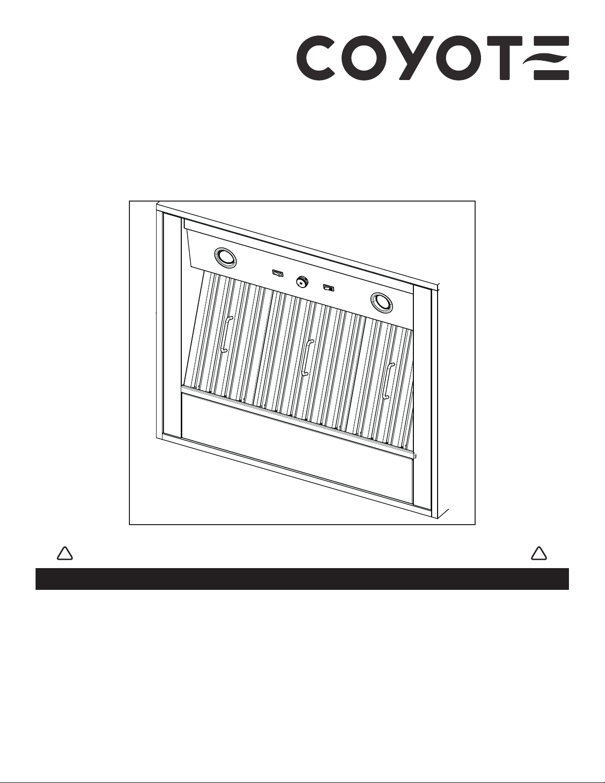
Coyote C1LINER Series User manual

C1LINER SERIES INSTALLATION INSTRUCTIONS
HB0303
INTENDED FOR OUTDOOR DOMESTIC COOKING ONLY
INSTALLER: LEAVE THIS MANUAL WITH HOMEOWNER.
HOMEOWNER: USE AND CARE INFORMATION ON PAGES 8 AND 9.
READ AND SAVE THESE INSTRUCTIONS
COYOTE OUTDOOR LIVING, INC.
www.coyoteoutdoor.com
23646 rev. 01
! !

2
TO REDUCE THE RISK OF FIRE, ELECTRIC SHOCK OR
INJURY TO PERSONS, OBSERVE THE FOLLOWING:
1. Use this unit only in the manner intended by the manufacturer. If
you have questions, contact the manufacturer at the address or
telephone number listed in the warranty.
2. Before servicing or cleaning unit, switch power off at service panel
and lock service disconnecting means to prevent power from
being switched on accidentally. When the service disconnecting
means cannot be locked, securely fasten a prominent warning
device, such as a tag, to the service panel.
3. Installation work and electrical wiring must be done by qualified
personnel in accordance with all applicable codes and standards,
including fire-rated construction codes and standards.
4. Sufficient air is needed for proper combustion and exhausting of
gases through the flue (chimney) of fuel burning equipment to
prevent backdrafting.Follow the heating equipment manufacturer’s
guidelines and safety standards such as those published by the
National Fire Protection Association (NFPA) and the American
Society for Heating, Refrigeration and Air Conditioning Engineers
(ASHRAE) and the local code authorities.
5. When cutting or drilling into wall or ceiling, do not damage
electrical wiring and other hidden utilities.
6. Ducted fans must always be vented to the outdoors.
7. Do not use this unit with any solid-state speed control device.
8. To reduce the risk of fire, use only metal ductwork.
9. This unit must be grounded and protected by a GFCI.
10. Suitable for use in damp locations only when installed in a GFCI-
protected branch-circuit.
11. This unit is not designed to be used with a charcoal grill.
12. When applicable local regulations comprise more restrictive
installation and/or certification requirements, the aforementioned
requirements prevail on those of this document and the installer
agrees to conform to these at his own expenses.
TO REDUCETHE RISK OF A RANGETOP GREASE FIRE:
a) Never leave surface units unattended at high settings. Boilovers
cause smoking and greasy spillovers that may ignite. Heat oils
slowly on low or medium settings.
b) Always turn power pack ON when cooking at high heat or when
flambeing food (i.e.: Crêpes Suzette, Cherries Jubilee, Peppercorn
Beef Flambé).
c) Clean ventilating fans frequently. Grease should not be allowed to
accumulate on fan, filters or in exhaust ducts.
d) Use proper pan size. Always use cookware appropriate for the
size of the surface element.
1. For general ventilating use only. Do not use to exhaust hazardous
or explosive materials and vapors.
2. To avoid motor bearing damage and noisy and/or unbalanced
impellers, keep drywall spray, construction dust, etc. off the power
pack.
3. Your power pack motor has a thermal overload which will
automatically shut off the motor if it becomes overheated. The
motor will restart when it cools down. If the motor continues to
shut off and restart, have the power pack serviced.
4. The power pack must be installed at least 36” above the cooking
surface.
5. Two installers are recommended because of the large size and
weight of this unit.
6. To reduce the risk of fire and to properly exhaust air, be sure to
duct air outside — Do not exhaust air into spaces within walls or
ceiling or into attics, crawl space or garage.
7. This product is equipped with a thermostat which may start blower
automatically. To reduce the risk of injury and to prevent power
from being switched on accidentally, switch power off at service
panel and lock or tag service panel.
8. To reduce the risk of fire and electrical shock, the C1LINER
Series models should only be installed with the C1BLOW1200
INTERNAL BLOWER. Other blowers cannot be substituted.
9. Please read specification label on product for further information
and requirements.
WARNING
! CAUTION
TO REDUCETHE RISK OF INJURYTO PERSONS INTHE
EVENT OF A RANGE TOP GREASE FIRE, OBSERVE
THE FOLLOWING*:
1. SMOTHER FLAMES with a close-fitting lid, cookie sheet or metal
tray, then turn off the burner. BE CAREFULTO PREVENT BURNS.
IF THE FLAMES DO NOT GO OUT IMMEDIATELY, EVACUATE
AND CALL THE FIRE DEPARTMENT.
2. NEVER PICK UP A FLAMING PAN — You may be burned.
3. DO NOT USE WATER, including wet dishcloths or towels — This
could cause a violent steam explosion.
4. Use an extinguisher ONLY if:
A. You own a Class ABC extinguisher and you know how to
operate it.
B. The fire is small and contained in the area where it started.
C. The fire department has been called.
D. You can fight the fire with your back to an exit.
* Based on “Kitchen Fire Safety Tips” published by NFPA.
WARNING
!

3
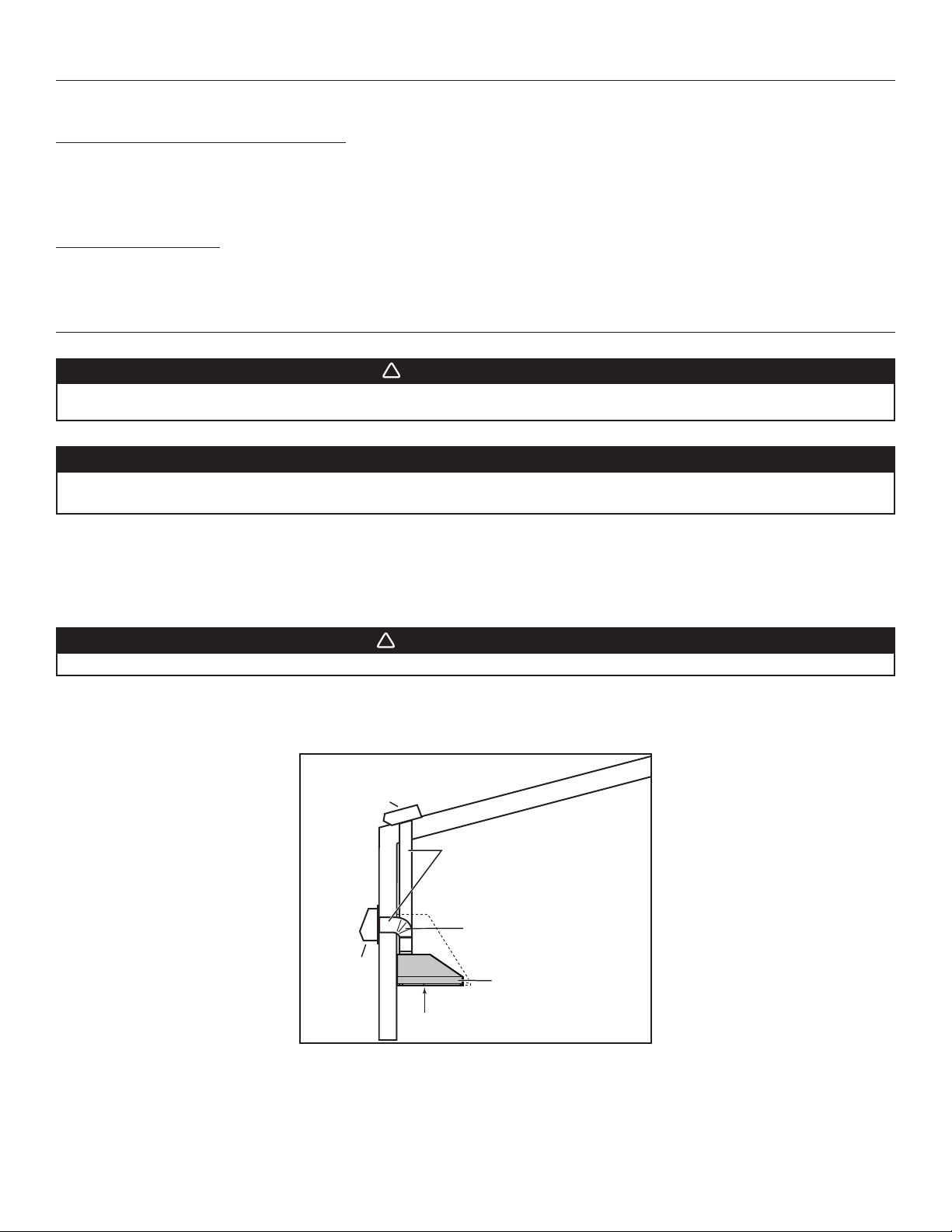
These power packs must be installed with the C1BLOW1200 blower (sold separately). Do not substitute for an other blower.
Plan where and how the ductwork will be installed. A straight, short duct run will allow the hood to perform most efficiently.
Install 10-inch ductwork, elbows and roof or wall cap. Connect metal ductwork to the cap and work back towards the hood location. Use
2" metal foil duct tape to seal the joints.
Run 3-wire power supply cable to installation location.
The power pack must be installed at least 36’’ above the cooking surface
HH0270A
POWER PACK
ROOF CAP
WALL
CAP
10” ROUND DUCT
36” ABOVE COOKING SURFACE
10” ROUND ELBOW
WARNING
!
The power cable must be a GFCI protected branch circuit.
NOTE: Before proceeding to the installation, check the contents of the box. If items are missing or damaged, contact the manufacturer.
Make sure that the following items are included:
- Power Pack
- Accessories • Baffle filters with handles
• 10” round adapter
• Bag of parts including: 1 wire clamp, 2 waterproof wire connectors, 9 no. 8 x 5/8” type A screws,
2 no. 8-18 x 3/8” screws, 1 suction cup.
Parts sold separately:
• Blower assembly model C1BLOW1200.
WARNING
!
When performing installation, servicing or cleaning the unit, it is recommended to wear safety glasses and gloves.
This power pack is not designed for use with a charcoal grill.
CAUTION
This range hood is intended for outdoor covered patio or lanai area. As with all electric appliances, this unit must
be protected from the effects of the weather.
1. PREPARE THE INSTALLATION
2. INSTALL THE DUCTWORK AND ELECTRICAL WIRING
4
3. CUSTOM HOOD PREPARATION
WARNING
!
When building a custom hood, always follow all applicable construction codes and standards.
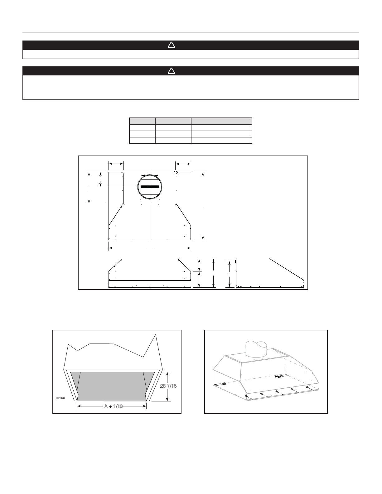
The custom hood must be constructed to fit the size and shape of the power pack. See chart and illustration below for details.
SIZE TOTAL WEIGHT POWER PACK WIDTH (A)*
36” 66 LB. 34 7/16”
42” 73 LB. 40 7/16”
48” 80 LB. 46 7/16”
12
6 3/4
5 1/4
A
6 1/4
13 1/4
6 3/16
6 1/2
≈28 3/8
11 1/16
HD1072
C
L
*Includes rivet heads.
Since the power pack mounting holes are located on the front and rear sides, plan to install a wood frame in the front and sides to support
the power pack using the screws provided in the parts bag.
For an aesthetic gap around the power pack, measure the actual width of the power pack and add 1/16”.
A + 1/16
HD1073
28 7/16
"
HH0271
WARNING
!
The custom wood hood must be positively secured to wall studs or other wooden framework behind the wall.
Make sure it is capable of supporting its own weight and the weight of the power pack. Failure to do so may cause
personal injury or damage to surfaces below.
DIMENSIONS
IN INCHES

5
4. REMOVE THE FILTERS
Remove the tape from the filters. Remove the filters from the power pack, and set
aside.
It is recommended to start with the center one(s).
HD1069
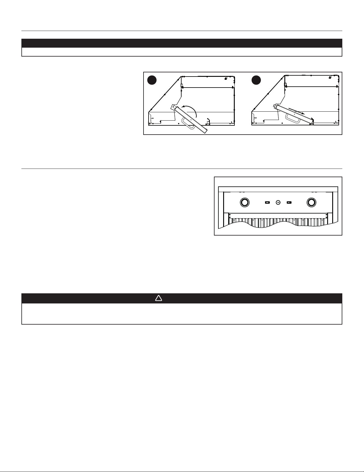
5. REMOVE THE GREASE DRIP RAIL
A. Lift and rotate the grease drip rail to disengage it from
the bottom panel.
B. Slide grease drip rail all the way to the left or right and
lift the opposite end to disengage the other end from
the bottom panel. Remove it from the power pack and
set aside for later use.
6. REMOVE THE BOTTOM PANEL
Using a Phillips screwdriver, remove both bottom panel retaining screws and set
aside.
Disassemble bottom panel from power pack and set aside.
HD1070
A B
HO0338
RETAINING
SCREW
RETAINING
SCREW

6
7. INSTALL THE ADAPTER
Remove the 10-inch round adapter from inside the power pack, and
install it on the top using 2 no. 8-18 x 3/8” Phillips screws, and the small
notches around the adapter.
HJ0185
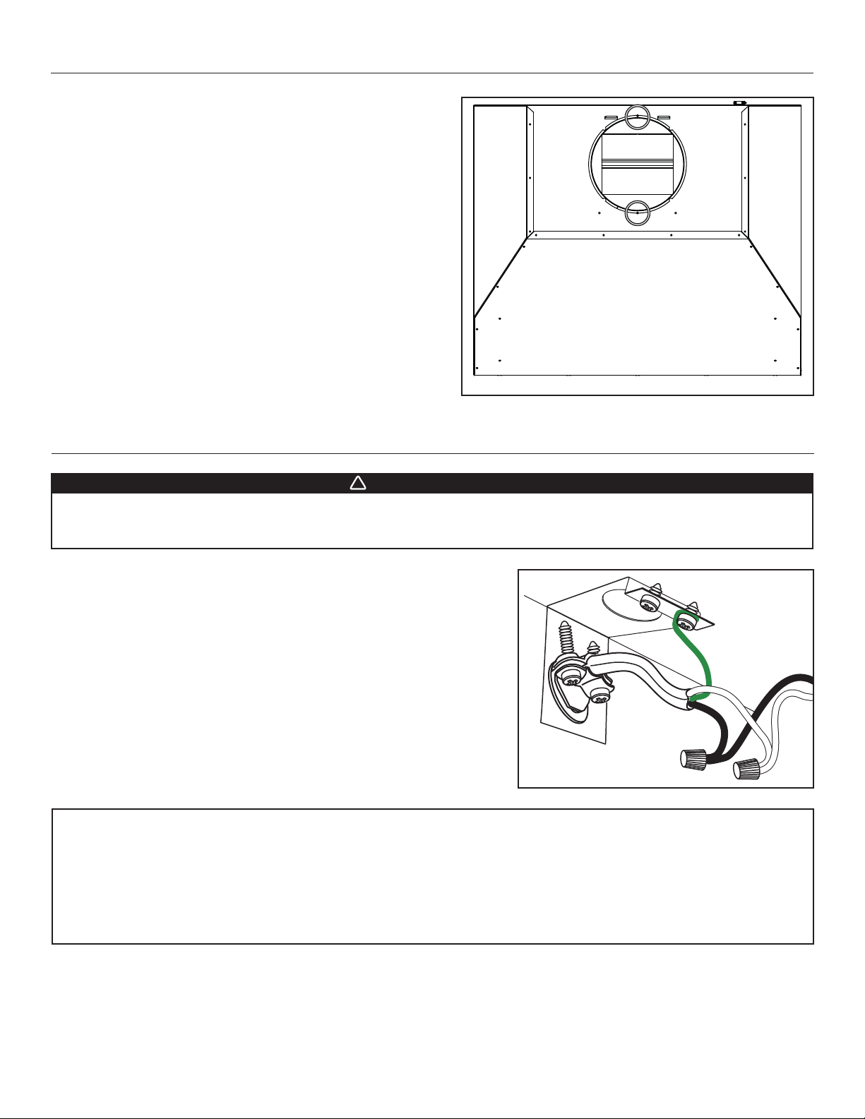
From inside the power pack, remove the wiring box cover by removing both
retaining screws and set aside. Install the wire clamp included in the parts bag in
the electrical hole in the back of the hood.
Position the power pack below the installed custom hood.
Insert the house wiring cable through the wire clamp, and tighten the wire clamp
to secure the cable. Connect the cable into wiring box using waterproof wire
connectors. Connect BLACK to BLACK, WHITE to WHITE and GREEN or bare wire
under GREEN ground screw. DO NOT FORGET TO CONNECT THE GROUND.
Reinstall wiring box cover, making sure not to pinch wires.
8. CONNECT WIRING
WARNING
!
Risk of electric shock. Electrical wiring must be done by qualified personnel in accordance with all applicable
codes and standards. Before connecting wires, switch power off at service panel and lock service disconnecting
means to prevent power from being switched on accidentally.
HE0059
WATERPROOF WIRE CONNECTORS INSTRUCTIONS:
1. Strip wires 3/8".
2. Align frayed strands or conductors.
3. Do not pre-twist. Place stripped wires together with ends even, but lead smaller stranded wires slightly ahead of larger solid or
stranded wire.
4. Twist connector onto wires pushing firmly until hand-tight. DO NOT over torque.
5. When inserting wires into connectors, some sealant may leak out.Wipe off excess sealant in and around conductors.DO NOT REUSE.

7
CAUTION
Take care not to kink ducting when installing the power pack.
Using the provided no. 8 x 5/8” screws, install the power pack inside the custom hood. Start
with 2 screws in the front corners, then install 4 screws for the sides and use the remaining
screws to finalize securing the front power pack. (See figure at right for mounting screw
specific locations.)
Make sure the adapter enters the ducting. When there is access to the top of the power
pack, seal connections with metal foil duct tape. HH0271
10. INSTALL THE BLOWER IN THE POWER PACK
To install the C1BLOW1200 dual blower inside the power pack, first remove the blower plate from
inside the power pack, and lay it on a protected surface.
Mount both blowers on the blower plate using 8 hexagonal nuts included with the blowers (see
illustration A). Make sure that both holes in the blower plate are entirely covered by the blowers.The
blowers should be 0.5 inch apart (see illustration B).
To install the blower plate and blowers into the power pack, insert the blower plate tabs into the slots
and reinstall both nuts previously removed to secure the blower plate to the power pack.
Connect the blower power cord to the power pack, and tie the blower power cord using the
preinstalled twist tie.
HD1067
HD1068A
0.5"
9. INSTALL THE POWER PACK
Reinstall the bottom panel using the screws
removed previously and a Phillips screwdriver. Reinstall the drip grease rail.
RETAINING
SCREW
HD1071
11. REINSTALL THE BOTTOM PANEL AND GREASE DRIP RAIL
HO0343
RETAINING
SCREW
A B
CAUTION
Remove the protective plastic film covering the bottom panel and the grease drip rail before reinstalling them.
8
12. REINSTALL THE FILTERS
CAUTION
Remove the protective plastic film covering the filters before installing them.
It is recommended to install side filters first and to finish with center one(s).
1. Insert the end with the spring of the baffle filter
into the front channel of the power pack.
2. Raise the other end toward the inside of power
pack and insert in the grease drip rail of the
power pack.
1
HD0526
2
13. OPERATION
BLOWER
The blower is operated using two controls.
Use the on/off rocker switch (1) to start and stop the blower. When turned ON, the
switch turns red and the blower operates at the speed set by the speed control
knob (2).
Turn the speed control knob counterclockwise to increase blower speed –
clockwise to decrease speed.
COOKTOP LIGHTING (HALOGEN)
Use the on/off rocker switch (3) to turn the halogen lights ON or OFF.
1) ON/OFF blower switch
2) Blower speed control knob
3) Halogen light switch
HEAT SENTRY™
This power pack is equipped with a Heat Sentry™ thermostat. This thermostat is a device that will turn on the blower to high speed if it
senses excessive heat above the cooking surface.
1) If blower is OFF - it turns blower ON to high speed.
2) If blower is already ON - it sets blower on high speed.
When the temperature drops to normal, the blower will return to its original setting.
WARNING
!
The HEAT SENTRY can start the blower during a range top fire or other excessive heat situations even if the power
pack is turned off. In this case, it is impossible to turn the blower OFF using control panel switch. To stop the
blower, disconnect blower cord plug.
1 2 3
HC0087

9
14. USE AND CARE
Baffle Filters
The baffle filters should be cleaned frequently. Use a warm detergent solution. Wash more often if your cooking style generates greater
grease — like frying foods or wok cooking.
Remove baffle filters by pushing them towards the front of power pack and rotating filters downward. Baffle filters are dishwasher safe.Allow
filters to dry completely before reinstalling them in the power pack.
Clean all-metal filters in the dishwasher using a non-phosphate detergent. Discoloration of the filter may occur if using phosphate detergent
or as a result of local water conditions — but this will not affect filter performance. This discoloration is not covered by the warranty.
Grease Drip Rail
The grease drip rail should be cleaned frequently. Remove it from the power pack and use a warm detergent solution. As with the baffle
filters, wash more often if your cooking style generates greater grease — like frying foods or wok cooking. Allow the grease drip rail to dry
completely before reinstalling it in the power pack.
General cleaning instructions
Stainless steel cleaning:
Avoid when choosing a detergent:
- Any cleaners that contain bleach will attack stainless steel.
- Any products containing: chloride, fluoride, iodide, bromide will deteriorate surfaces rapidly.
- Any combustible products used for cleaning such as acetone, alcohol, ether, benzol, etc., are highly explosive and should never be
used close to a range.
Do:
• Regularly wash with clean cloth or rag soaked with warm water
and mild soap or liquid dish detergent.
• Always clean in the direction of original polish lines.
• Always rinse well with clear water (2 or 3 times) after cleaning.
Wipe dry completely.
• You may also use a specialized household stainless steel
cleaner.
Don’t:
• Use any steel or stainless steel wool or any other scrapers to
remove stubborn dirt.
• Use any harsh or abrasive cleansers.
• Allow dirt to accumulate.
• Let plaster dust or any other construction residues reach the
power pack. During construction/renovation, cover the power
pack to make sure no dust sticks to stainless steel surface.
15. LIGHT BULBS REPLACEMENT
This power pack is equiped with two 120 V, 50 W, MR16 with GU10 base, shielded halogen bulbs.
To remove the bulbs, press suction cup tool (included in parts bag) on bulb and rotate counterclockwise to disengage the bulb leads from
their grooves.
Install the new bulbs by placing the bulb leads into their grooves in the socket. Gently push upwards and turn clockwise until secure.
WARNING
!
Do not touch lamps during or soon after operation. Burns may occur. In order to prevent the risk of personal injury,
only install shielded halogen lamps. Also, never install a cool beam, a dichroic lamp, a lamp not suitable for use in
recessed luminaires or identified for use in enclosed fixtures.
HR0212
BULB LEADS
BULB LEAD GROOVES
(IN SOCKET)
SUCTION CUP TOOL
10
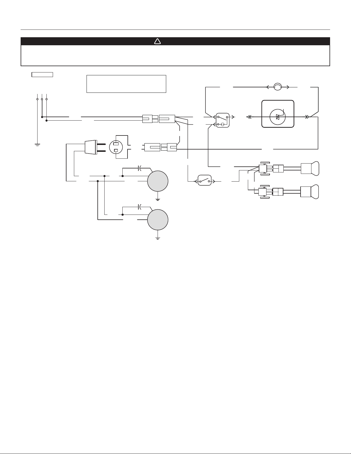
16. WIRING DIAGRAM
WARNING
!
Risk of electrical shock. Electrical wiring must be done by qualified personnel in accordance with all applicable
codes and standards. Before connecting wires, switch power off at service panel and lock service disconnecting
means to prevent power from being switched on accidentally.
M
M
Neutral
Line
Ground
120 V AC
Lamp
Lamp switch
HS
THERMOSTAT
BLK
RED RED
BLK
BLK
WHT
Fan switch
SPEED CONTROL
WHT
BLK
YEL
WHT
WHT
BLK
BLK WHT
BLK
Lamp
WHT
YEL
WHT
BLK WHT
COLOR CODE
BLK
RED
BLACK
RED
WHT
YEL
WHITE
YELLOW
REF: 70103_REV-A
HE0337A
BLK
WHT

11
17. SERVICE PARTS
B
C
D
E
F
G
H
I
J
K
L
M
KEY
NO.PART NO. DESCRIPTION QUANTITY
36" 42" 48"
1 SV08541 10” ROUND ADAPTER 111
2 SV16569 LIGHT SOCKET AND TRIM ASSEMBLY 222
3 SV05921 GU10 HALOGEN BULB 222
4 SV02563 LIGHT ROCKER SWITCH 111
5 SV03501 BLOWER SPEED CONTROL 111
6 SV08549 BLOWER SPEED CONTROL KNOB 111
7 C1BLOW1200* BLOWER ASSEMBLY 111
8
SV65734 GREASE RAIL FOR 36-IN.-WIDE POWER PACK 100
SV65735 GREASE RAIL FOR 42-IN.-WIDE POWER PACK 010
SV65736 GREASE RAIL FOR 48-IN.-WIDE POWER PACK 001
9 SV08337 SPRINGS FOR BAFFLE FILTERS (SET OF 6) 1 1 1
10 SV60675 BAFFLE FILTER WITH SPRING 11.84” X15.125” 1 3 2
SV60716 BAFFLE FILTER WITH SPRING 8.84” X15.125” 2 0 2
11 SV03503 BLOWER ROCKER SWITCH 111
12 SV03435 HEAT SENTRY™ THERMOSTAT 111
** SV23645
PARTS BAG: 1 WIRE CLAMP, 2 WATERPROOF WIRE CONNECTORS,
9 NO. 8 X5/8” TYPE A SCREWS, 2 NO. 8-18 X3/8” SCREWS,
1SUCTION CUP.
111
* PART SOLD SEPARATELY
** NOT SHOWN
REPLACEMENT PARTS AND REPAIRS
In order to ensure your unit remains in good
working condition, you must use Coyote
Outdoor Living Inc. genuine replacement
parts only. Coyote Outdoor Living Inc. genuine
replacement parts are specially designed for
each unit and are manufactured to comply
with all the applicable certification standards
and maintain a high standard of safety. Any
third party replacement part used may cause
serious damage and drastically reduce the
performance level of your unit, which will result
in premature failing. Coyote Outdoor Living
Inc. recommends to contact our Customer
Service Department at 855-520-1559 for all
replacement parts and service questions.

12
18. WARRANTY
TO THE MAXIMUM EXTENT PERMITTED BY LAW, THIS LIMITED WARRANTY AND THE REMEDIES SET FORTH BELOW ARE EXCLUSIVE
AND IN LIEU OF ALL OTHER WARRANTIES, REMEDIES AND CONDITIONS, WHETHER ORAL OR WRITTEN, EXPRESS OR IMPLIED. TO
THE MAXIMUM EXTENT PERMITTED BY LAW, COYOTE OUTDOOR LIVING, INC.ALSO SPECIFICALLY DISCLAIMS ANY AND ALL IMPLIED
WARRANTIES, INCLUDING, WITHOUT LIMITATION, WARRANTIES OF MERCHANTABILITY AND FITNESS FOR A PARTICULAR PURPOSE.
Coyote Outdoor Living, Inc. issues this limited warranty to the original purchaser at the original site of delivery with proof of purchase and
specifically warrants that the Outdoor Ventilation Hood or Liner, when subject to normal residential use, will be free from defects in workmanship
and materials for one year from the date of original purchase. This limited warranty is not transferable and specifically excludes any ventilation
product used in a commercial setting, where anyone other than the original purchaser (homeowner) would be using and maintaining the product.
This limited warranty specifically excludes all issues that may arise from surface corrosion, scratches, and discoloration during regular use. It
also does not extend to fluorescent lamp starters, tubes, halogen and incandescent bulbs, fuses, filters, ducts, roof caps, wall caps and other
accessories for ducting. This limited warranty does NOT COVER LABOR OR LABOR RELATED CHARGES and there will be shipping and
handling charges for the delivery of any needed part(s).
Coyote Outdoor Living, Inc.’s obligation under this limited warranty is limited solely to repair or replacement, at our option, of the pertinent
component during the warranty period, and the extent of any liability of Coyote Outdoor Living, Inc. under this warranty is limited to repair or
replacement. This limited warranty does not cover normal wear of parts or damage resulting from any of the following: negligent use or misuse
of the product, improper maintenance or repair, faulty installation, use contrary to operating instructions, or alteration by any person other than a
factory service center. The above warranty periods are not extended by any repair or replacement.
WARRANTY CLAIM PROCEDURE: If you require service or parts for your Coyote Grill, please contact our Warranty Service Center for
factory direct assistance. Our hours of operation are 8 am to 4:30 pm CST. The phone number is 855.520.1559 and the email address is
support@coyoteoutdoor.com. You may also fill out warranty claims online at www.coyoteoutdoor.com. Please have your model number, serial
number and proof of purchase available for any warranty claim.
Coyote Outdoor Living, Inc. may require the return of defective parts for examination before issuing replacement parts. If you are required to return
defective parts, shipping charges must be prepaid by the customer. Upon examination and to Coyote Outdoors determination, if the original part
is proven defective, Coyote Outdoor may approve your claim and elect to replace such parts without charge. In every instance, the customer is
responsible for shipping and handling of replacement parts. Component repair or replacement is the exclusive remedy under this limited warranty
and Coyote Outdoor shall not be liable for any incidental or consequential damages.
This limited warranty does not cover any failures or operating difficulties due to accidents, abuse, misuse, alteration, misapplication, vandalism,
improper installation, maintenance or service, or damages caused by flashback fire or grease fire.This limited warranty does not cover scratches,
dents, corrosion or discoloration caused by weather, heat, abrasive and chemical cleaners, pool or spa chemicals, and/or any tools used in the
assembly or installation of this unit. This limited warranty does not cover paint loss, surface rust, corrosion or stainless steel discoloration which
is considered normal wear and tear. This limited warranty does not cover the cost of any inconvenience, personal injury, or property damage due
to improper use or product failure. Deterioration or damage due to severe weather conditions such as hail, hurricanes, earthquakes, tsunamis,
tornadoes, terrorism, discoloration due to exposure to chemicals either directly or in the atmosphere, Acts of God/forces of Nature are not covered
by this limited warranty.
INSTRUCTIONS D'INSTALLATION
HOTTES ENCASTRABLES SÉRIE C1LINER
HB0303
CONÇUES POUR UN USAGE DOMESTIQUE EXTÉRIEUR SEULEMENT
INSTALLATEUR : LAISSER CE GUIDE AU PROPRIÉTAIRE.
PROPRIÉTAIRE : DIRECTIVES D’UTILISATION ET D’ENTRETIEN
EN PAGES 8 ET 9.
LIRE ET CONSERVER CES DIRECTIVES
COYOTE OUTDOOR LIVING, INC.
www.coyoteoutdoor.com
23646 rév. 01
! !

2
AFIN DE RÉDUIRE LES RISQUES D’INCENDIE,
D’ÉLECTROCUTION OU DE BLESSURES CORPORELLES,
SUIVEZ LES DIRECTIVES SUIVANTES :
1. N’utilisez cet appareil que de la façon prévue par le
manufacturier. Si vous avez des questions, contactez le
manufacturier à l’adresse ou au numéro de téléphone indiqués
dans la garantie.
2. Avant de réparer ou de nettoyer l’appareil, couper l’alimentation
électrique en verrouillant le panneau de distribution afin
d’éviter sa remise en marche accidentelle. Si le panneau de
distribution ne peut être verrouillé, y fixer un avertissement en
évidence, telle qu’une étiquette de couleur vive.
3. Les travaux d’installation et de raccordement électrique doivent
être effectués par une personne qualifiée, conformément
aux codes et aux standards de construction, incluant ceux
concernant la protection contre les incendies.
4. Une quantité d’air adéquate est requise afin d’assurer une
bonne combustion et l’évacuation des gaz par la cheminée
dans le cas des équipements alimentés au gaz afin de prévenir
les retours de cheminée. Conformez-vous aux instructions et
aux standards de sécurité des manufacturiers d’équipement de
chauffage, tel qu’ils sont publiés par la National Fire Protection
Association (NFPA) et l’American Society for Heating,
Refrigeration and Air Conditioning Engineers (ASHRAE) ainsi
que les responsables des codes locaux.
5. Veillez à ne pas endommager le câblage électrique ou d’autres
équipements non apparents lors de la découpe ou du perçage
du mur ou du plafond.
6. Les ventilateurs avec conduits doivent toujours évacuer l’air
à l’extérieur.
7. Ne pas utiliser cet appareil avec une commande de vitesse à
semiconducteur additionnelle.
8. Afinde réduireles risquesd’incendie,n’utilisez que desconduits
de métal.
9. Cet appareil doit être mis à la terre et protégé par un DDFT
(disjoncteur de fuite à la terre).
10.Convient à une utilisation dans des lieux humides seulement
lorsqu’elle est raccordée à un DISJONCTEUR DE FUITE À LA
TERRE (DDFT).
11. Cet appareil n’est pas conçu pour être utilisé avec un barbecue
au charbon de bois.
12.Lorsqu’une réglementation est en vigueur et qu’elle comporte
des exigences d’installation et/ou de certification plus
restrictives, lesdites exigences prévalent sur celles de ce
document et l’installateur entend s’y conformer à ses frais.
AFIN DE RÉDUIRE LES RISQUES DE FEU
DE CUISINIÈRE :
a) Ne jamais laisser les appareils de cuisson sans surveillance
lorsqu’ils sont réglés à feu vif. Les débordements engendrent
de la fumée et des déversements graisseux pouvant
s’enflammer. Chauffez l’huile lentement, à feu doux ou moyen.
b) Mettez toujours la hotte en marche lorsque vous cuisinez à feu
vif ou que vous cuisinez des mets flambés (par ex. : crêpes
Suzette, cerises jubilé, steaks au poivre flambés).
c) Nettoyez régulièrement la (les) roue(s) du ventilateur. Ne
laissez pas la graisse s’accumuler sur le ventilateur, les filtres
ou les conduits d’évacuation.
d) Utilisez le bon format de casserole. Servez-vous toujours de
casseroles et d’ustensiles appropriés à la dimension de la
surface chauffante.
1. Pour usage domestique seulement. Ne pas utiliser pour
évacuer des vapeurs ou des matières dangereuses
ou explosives.
2. Afin d’éviter tout dommage au moteur et de débalancer ou de
rendre bruyantes les roues de moteurs, garder votre appareil à
l’abri des poussières de gypse et de construction/rénovation, etc.
3. Le moteur de votre hotte possède une protection thermique
qui éteindra automatiquement le moteur s’il devient surchauffé.
Le moteur redémarrera automatiquement une fois refroidi. Si
le moteur continue à arrêter et à redémarrer, faites-le vérifier.
4. Pour une meilleure évacuation des odeurs de cuisson, le
bas de votre hotte doit être situé à une distance de 36 po
au-dessus de la surface de cuisson.
5. Deux installateurs sont recommandés lors de l’installation vu
la grande dimension et le poids de cet appareil.
6. Afin de réduire les risques d’incendie, assurez-vous d’évacuer
l’air à l’extérieur. Ne pas évacuer l’air dans des espaces
restreints comme l’intérieur des murs ou plafond ou dans le
grenier, faux plafond ou garage.
7. Cet appareil est équipé d’un thermostat pouvant faire démarrer
le ventilateur automatiquement. Afin de réduire le risque de
blessure, couper le courant à partir du panneau électrique
et le verrouiller ou apposer un avertissement sur le panneau afin
deprévenirquelahottene soitmiseenmarcheaccidentellement.
8. Afin de réduire les risques d’incendie et d’électrocution, la
hotte encastrable Coyote de série C1LINER doit être installée
uniquement avec le ventilateur intérieur C1BLOW1200 (vendu
séparément). Aucun autre ventilateur ne doit être utilisé.
9. Veuillez consulter l’autocollant apposé à l’intérieur du produit
pour plus d’information ou autres exigences.
AVERTISSEMENT
!
ATTENTION
AVERTISSEMENT
!
AFIN D’ÉVITER TOUT RISQUE DE BLESSURES LORS D’UN
FEU DE CUISINIÈRE, SUIVEZ CES DIRECTIVES* :
1. Étouffez les flammes avec un couvercle hermétique, une tôle à
biscuits ou un plateau métallique et ensuite, éteindre le brûleur.
PRENEZ SOIN D’ÉVITER les brûlures. SI LES FLAMMES
NE S’ÉTEIGNENT PAS IMMÉDIATEMENT, ÉVACUEZ LES
LIEUX ET APPELEZ LES POMPIERS.
2. NE PRENEZ JAMAIS UNE CASSEROLE EN FLAMMES
DANS VOS MAINS. Vous pourriez vous brûler.
3. N’UTILISEZ PAS D’EAU, incluant un linge à vaisselle ou une
serviette mouillée, cela pourrait occasionner une violente
explosion de vapeur.
4. N’utilisez un extincteur QUE DANS LE CAS OÙ :
A. Vous savez qu’il s’agit d’un extincteur de classe ABC et
que vous en connaissez le fonctionnement.
B. Le feu est petit et limité à l’endroit où il a débuté.
C. Les pompiers ont été avisés.
D. Vous pouvez combattre l’incendie en ayant accès à une
sortie de secours.
*Tirées du Kitchen Fire Safety Tips publié par la NFPA.
3
Ces hottes encastrables doivent être munies de l'ensemble ventilateur C1BLOW1200 (vendu séparément). N'utiliser aucun autre modèle
de ventilateur.
Planifier le réseau de conduit. Des conduits courts et droits permettront un maximum d'efficacité.
Installer des conduits, coudes et capuchon de toit de 10 po. Raccorder les conduits de métal au capuchon, puis acheminer le conduit
jusqu'à l'emplacement de la hotte encastrable. Sceller les joints avec du ruban adhésif de métal de 2 po de largeur.
Acheminer un câble d’alimentation électrique à 3 conducteurs jusqu’à l’emplacement de la hotte.
La hotte encastrable doit être installée à au moins 36 po au-dessus de la surface de cuisson.
HH0270F
HOTTE ENCASTRABLE
CAPUCHON DE TOIT
CAPUCHON
MURAL
CONDUIT ROND DE 10 PO
36 PO AU-DESSUS
DE LA SURFACE DE CUISSON
COUDE ROND DE 10 PO
AVERTISSEMENT
!
Le fil d’alimentation électrique doit être raccordé à un disjoncteur de fuite à la terre (DDFT).
NOTE: Vérifier le contenu de la boîte avant de procéder à l'installation. Si des articles sont endommagés ou manquants, contacter le
fabricant.
S'assurer que les articles suivants sont inclus:
- Hotte encastrable
- Accessoires • Filtres à chicanes avec poignées
• Adaptateur 10 po rond
• Sac de pièces: 1 serre-fils, 2 capuchons de connexion étanches, 9 vis type A no8 x 5/8 po,
2 vis no8-18 x 3/8 po, 1 ventouse.
Pièce vendue séparément:
• Ensemble ventilateur C1BLOW1200.
AVERTISSEMENT
!
Il est recommandé de porter des lunettes et des gants de sécurité lors de l’installation, de l’entretien et de la
réparation de cet appareil. Cette hotte n’est pas conçue pour être utilisée avec un barbecue au charbon de bois.
ATTENTION
Cette hotte est conçue pour être utilisée sur un patio couvert ou une véranda. Comme tous les électroménagers,
cet appareil doit être à l’abri des intempéries.
1. PRÉPARER L'INSTALLATION
2. INSTALLER LES CONDUITS ET LE CÂBLAGE ÉLECTRIQUE

4
3. PRÉPARATION DE L'ARMOIRE POUR HOTTE
AVERTISSEMENT
!
Toujours suivre les codes et standards en vigueur lors de la construction de l'armoire pour hotte.
Construire l'armoire pour hotte en fonction des dimensions et du poids de la hotte encastrable. Consulter le tableau et les schémas
ci-dessous pour plus de détails.
FORMAT POIDS TOTAL LARGEUR DE LA HOTTE
ENCASTRABLE (A)*
36 PO 66 LB 34 7/16 PO
42 PO 73 LB 40 7/16 PO
48 PO 80 LB 46 7/16 PO
*Incluant les têtes de rivets.
Puisque les trous de fixation de la hotte encastrable sont situés sur le devant et les côtés de celle-ci, prévoir un cadrage de bois à l'avant
et sur les côtés. Cela permettra de fixer la hotte encastrable solidement au moyen des vis fournies.
Afin d'éviter des espaces trop larges entre la hotte encastrable et l'armoire, mesurer la largeur de la hotte encastrable,
puis ajouter 1/16po.
A + 1/16
HD1073
28 7/16
"
HH0271
AVERTISSEMENT
!
La charpente de bois doit être fixée solidement aux montants ou autre structure derrière la cloison. S’assurer
qu’elle puisse supporter son propre poids en plus de celui de la hotte encastrable. Ne pas suivre cette directive peut
entraîner des blessures corporelles ou des dommages aux surfaces situées en dessous.
12
6 3/4
5 1/4
A
6 1/4
13 1/4
6 3/16
6 1/2
≈28 3/8
11 1/16
HD1072
C
LLES DIMENSIONS
SONT EN POUCES

5
4. RETIRER LES FILTRES
Retirer le ruban adhésif des filtres, puis retirer les filtres de la hotte encastrable et les
mettre de côté.
Il est recommandé de commencer avec le filtre (ou les filtres) du centre.
HD1069
5. RETIRER LA GOUTTIÈRE
A. Soulever en tournant la gouttière pour la dégager du
panneau inférieur.
B. Glisser un des côtés de la gouttière et soulever l'autre
pour dégager la gouttière du panneau inférieur. Mettre
la gouttière de côté.
6. RETIRER LE PANNEAU INFÉRIEUR
À l'aide d'un tournevis Phillips, retirer les deux vis retenant le panneau inférieur.
Retirer le panneau inférieur de la hotte encastrable, puis le mettre de côté avec
les vis.
HD1070
A B
HO0338
VIS DE
RETENUE
VIS DE
RETENUE
6
7. INSTALLER L'ADAPTATEUR
Retirer l'adaptateur 10 po rond de l'intérieur de la hotte encastrable, puis
l'installer sur le dessus de celle-ci à l'aide de 2 vis Phillips no8-18 x 3/8po
et des petites encoches dans le pourtour de l'adaptateur.
HJ0185
Depuis l'intérieur de la hotte, retirer les 2 vis de retenue du couvercle du
compartiment électrique, puis retirer ce dernier. Installer le serre-fils dans le trou
prévu à cet effet au dos de la hotte encastrable.
Placer la hotte encastrable sous l'armoire où son installation est prévue.
Insérer le câble électrique dans la hotte encastrable par le passe-fils, puis serrer
celui-ci. Effectuer le branchement électrique à l'aide des connecteurs étanches
fournis. Connecter le fil NOIR au fil NOIR, le fil BLANC au fil BLANC et le fil VERT
ou dénudé à la vis de mise à la terre.NE PAS OUBLIER DE CONNECTER LA MISE
À LA TERRE.
Réinstaller le couvercle du compartiment électrique, en s'assurant de ne pas
pincer les fils.
8. BRANCHEMENT ÉLECTRIQUE
HE0059
AVERTISSEMENT
!
Risque d’électrocution. Le branchement électrique doit être effectué par du personnel qualifié conformément aux
codes et aux standards en vigueur. Avant d’effectuer le branchement, coupez l’alimentation électrique au panneau
de distribution et verrouillez-le pour éviter une mise en marche accidentelle.
DIRECTIVES POUR L’UTILISATION DES CAPUCHONS DE CONNEXION ÉTANCHES :
1. Dégainer les fils d’une longueur de 3/8 po.
2. Égaliser les brins ou les conducteurs.
3. Ne pas les tordre. Rapprocher les fils et mettre leurs bouts égaux, sauf pour les fils à brins plus petits, lesquels doivent dépasser
légèrement des fils plus gros.
4. Insérer les fils dans le capuchon de connexion en poussant légèrement et tordre. NE PAS trop tordre.
5. Un peu de scellant pourrait s’échapper lors de l’insertion des fils dans le capuchon de connexion. Essuyer l’excès de scellant autour
des conducteurs. NE PAS RÉUTILISER.

7
ATTENTION
Prendre soin de ne pas gauchir les conduits en installant la hotte encastrable.
À l'aide des vis n° 8 x 5/8 po fournies, installer la hotte dans son armoire. Commencer
par les vis des coins avant gauche et droit, puis visser les 4 vis des côtés. Utiliser les
vis restantes pour fixer l’avant de la hotte encastrable. (Voir l’illustration ci-contre pour
l’emplacement spécifique des vis de montage.)
S’assurer que l’adaptateur entre dans le conduit. Si l’accès au dessus de la hotte
encastrable est ouvert, sceller le joint avec du ruban adhésif de métal. HH0271
9. INSTALLER LA HOTTE ENCASTRABLE
Pour installer le ventilateur double C1BLOW1200 à l'intérieur de la hotte encastrable, commencer
par retirer la plaque ventilateur de l'intérieur de celle-ci et la déposer sur une surface protégée.
Assembler les deux ventilateurs sur la plaque à l'aide de 8 écrous hexagonaux inclus avec les
ventilateurs (voir l'illustration A). S'assurer que les ventilateurs couvrent entièrement les deux
ouvertures de la plaque;les ventilateurs doivent être distants de 0 5 po l'un de l'autre (voir l'illustration B).
Remettre en place la plaque ventilateur avec les ventilateurs dans la hotte en insérant les pattes de
la plaque dans les fentes et fixer la plaque à la hotte à l'aide des 2 écrous retirés précédemment.
Brancher le cordon d'alimentation du ventilateur dans la hotte, puis attacher le câble d'alimentation
à l'aide de l'attache installée en usine.
HD1067
HD1068F
0,5 po
10. INSTALLER LE VENTILATEUR DANS LA HOTTE ENCASTRABLE
HO0343
A B
Réinstaller le panneau inférieur retiré
précédemment et le fixer à la hotte encastrable à
l'aide de ses 2 vis et d'un tournevis Phillips. Réinstaller la gouttière.
VIS DE
RETENUE
HD1071
VIS DE
RETENUE
11. RÉINSTALLER LE PANNEAU INFÉRIEUR ET LA GOUTTIÈRE
ATTENTION
Retirer la pellicule de plastique protectrice du panneau inférieur et de la gouttière avant de les remettre en place.

8
12. RÉINSTALLER LES FILTRES
ATTENTION
Retirer la pellicule de plastique protectrice des filtres avant de les remettre en place.
Il est recommandé d’installer d’abord les filtres situés aux extrémités et de terminer par le(s) filtre(s) du centre.
1. Introduire l'extrémité du filtre ayant le ressort
dans le rail avant de la hotte encastrable.
2. Lever l’autre bout du filtre à l’intérieur de la hotte
encastrable et l’introduire dans la gouttière.
1
HD0526
2
13. FONCTIONNEMENT
VENTILATEUR
Le ventilateur fonctionne à l’aide de 2 commandes.
Utiliser l’interrupteur à bascule MARCHE/ARRÊT (1) pour activer et arrêter le
ventilateur. Lorsque l’interrupteur est à la position marche, sa lumière rouge
s’allume et le ventilateur fonctionne à la vitesse réglée par le bouton de la
commande de vitesse (2).
Tourner le bouton de la commande de vitesse dans le sens antihoraire pour
augmenter la vitesse du ventilateur et dans le sens horaire pour ralentir sa vitesse.
ÉCLAIRAGE DE LA SURFACE DE CUISSON (HALOGÈNE)
Utiliser l’interrupteur à bascule MARCHE/ARRÊT (3) pour allumer et éteindre les
lumières.
1 2 3
HC0087
1) Interrupteur MARCHE/ARRÊT du ventilateur
2) Bouton de commande de vitesse du ventilateur
3) Interrupteur d'éclairage halogène
HEAT SENTRYMC
Cette hotte encastrable est équipée d’un thermostat Heat Sentry. Ce thermostat est un dispositif qui mettra en marche le ventilateur en
haute vitesse s’il détecte de la chaleur excessive au-dessus de la surface de cuisson.
1) Si le ventilateur n’est pas en marche, il activera le ventilateur en haute vitesse.
2) Si le ventilateur est déjà en marche, le ventilateur passera en haute vitesse.
Lorsque la température revient à la normale, le ventilateur retourne à sa vitesse d’origine.
AVERTISSEMENT
!
Le HEAT SENTRY peut mettre le ventilateur en marche même s’il est arrêté. Si tel est le cas, il est impossible d’arrêter
le ventilateur avec son interrupteur. Si vous devez arrêter le ventilateur, débrancher le cordon d'alimentation du
ventilateur.
Table of contents
Languages:
Other Coyote Ventilation Hood manuals


