CPMG Magma M1 Owner's manual
Melter Applicator
Owner/Operator Manual
2601 Niagara Lane · Plymouth, MN 55447 · (763) 557-1982 · (877) 841-0848 · Fax (763) 557-1971
Part # 161607 Rev D 11/15/16
Magma M1 & M2

Table of Contents
Shipping Papers and Information .................................................. 3
Safety Notes .................................................................................... 4
Weights and Dimensions................................................................ 5
Controls and Their Functions......................................................6-9
Start Up ..................................................................................... 10-11
Automatic Temperature Control Setting...................................... 12
Loading Empty Tank ..................................................................... 13
Cleanout Procedure ...................................................................... 14
Maintenance ............................................................................. 15-16
Fluid and Components Specs ...................................................... 17
Heat Transfer Oil Specs ................................................................ 18
Material Tank Capacity.................................................................. 19
Trouble Shooting Guide................................................................ 20
Parts Section
Wiring Diagrams....................................................................... 22-27
Complete Wiring Diagram ........................................................ 22
Engine Wiring Harness............................................................. 23
Control Panel ....................................................................... 24-25
Main Wiring Diagram ................................................................ 26
Burner Wiring............................................................................ 27
Hydraulic Schematic ..................................................................... 28
Hydraulic Manifold Parts List ....................................................... 29
Isuzu Diesel Engine and Pump Parts List
(See supplement for compressor models)......................... 30-31
Plumbing System Parts List .................................................... 32-33
Material Pump Parts List.......................................................... 34-35
Electrical Components.................................................................. 36
Sealing Hose and Wand................................................................ 37
Sealing Tips ................................................................................... 38
Agitation System Parts List.......................................................... 39
Oil Burner Parts List ..................................................................... 40
Combustion Chamber Parts List and Tank Insulation ................ 41
Miscellaneous Parts................................................................. 42-43
Fuel and Hydraulic Tank Components......................................... 44
Spare Parts Kit............................................................................... 45
Compressor Option....................................................................... 46

3
Shipping Papers and Information
A packet containing IMPORTANT INFORMATION has been enclosed with your Melter.
This packet contains:
1) Operation Instructions
2) Parts List
3) Warranty Information
4) Manufacturer's Documents
a) Engine
b) Material Pump
c) Burner (Diesel only)
IMPORTANT: This manual contains the basic information required to operate, main-
tain and repair the CIMLINE Melter you have purchased. The use of this manual in-
sures accurate adjustments, operation and proper lubrication of your equipment.
Please keep it handy.
Any parts orders or service problems relating to CIMLINE equipment should be di-
rected to the CIMLINE Parts Department at either (763) 557-1982 or (800) 328-3874.
When ordering parts, please have the following information available.
Serial Number: ____________________________
Model Number: ____________________________
Engine Model (H.P.): ____________________________
Engine Manufacturer: ____________________________
Pump Number: ____________________________
Replacement Part Number(s):

4
PLEASE READ AND UNDERSTAND ENTIRE OPERATORS MANUAL BEFORE
PROCEEDING
WARNING: Protective clothing must be worn. Refer to ANSI Regulations:
1) Wear gloves with wristlets.
2) Wear long sleeve shirt with sleeves rolled down and cuffs buttoned.
3) Wear a face shield.
4) Load Melter from ground level.
5) Keep material door closed at all times except when adding material.
6) Never stand on any part of the machine.
7) Do not pull, twist, stretch or kink the material hose.
8) Do not operate without safety cover on hose.
9) Do not touch exhaust stacks or mufflers.
10) Wear heavy leather boots or shoes.
11) Wear long pants with no cuffs.
12) Verify brakes are engaging before towing (including brake-away switch)
WARNING: Do not over fill the melting tank. For best results, add only as much
material as required for the job or a maximum of 75% of tank capacity.
(M-1 - 113 gallons, M-2 - 168 gallons & M-4 - 308 gallons).
WARNING: On a new Melter applicator or a unit that has been idle for some time,
slowly raise the oil temperature to 250º F and hold there for approximately
20 to 30 minutes. This will help get rid of any condensation that may be in
the oil chamber.
WARNING: Never leave machine unattended while it is running.
Safety Notes
5
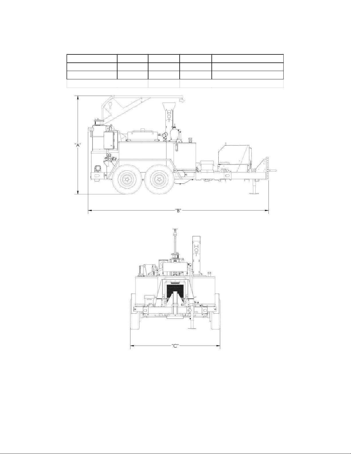
Model Number "A" in/cm "B" in/cm "C" in/cm Weight lbs/kg (empty)
M1 92/234 148/376 82/208 4000/1814
M2 90/229 164/417 81/206 4700/2132
Weights are without options
M2 shown
Weights and Dimensions

6
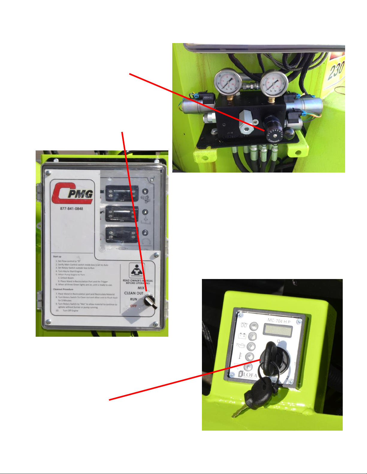
NOTE: This general outline will only familiarize you with the machine. Read through the en-
tire manual before putting this machine into operation.
1) Access Port: The sealing wand is placed in here when not in use. This allows operator to
continue circulating material through the hose to prevent material from cooling and freezing
up.
2) Loading Door (1 on Model 150): Place the material on safety door to load the melting tank.
3) Oil Temperature Gauge: Monitors the heat transfer oil temperature.
4) Material Temperature Gauge (optional): This gauge shows the temperature of material in-
side the melting tank. This gauge is for reference before pumping starts. Once pumping be-
gins, material controller will be an exact reading of material passing through the system. (Not
shown)
5) Micropanel ignition Switch: Use the key to turn the engine on and off.
6) Pressure Gauge: This gauge measures the pressure required to turn the agitator and the
material pump.
7) Sealing Hose Valve: This valve stops the material recirculating back into the material tank
causing it to go out of the wand.
8) Control Panel: The main control panel is used to control the direction of the material pump
and agitator, and you can also monitor the temperature of the material and heat transfer oil.
Controls and Their Functions

7
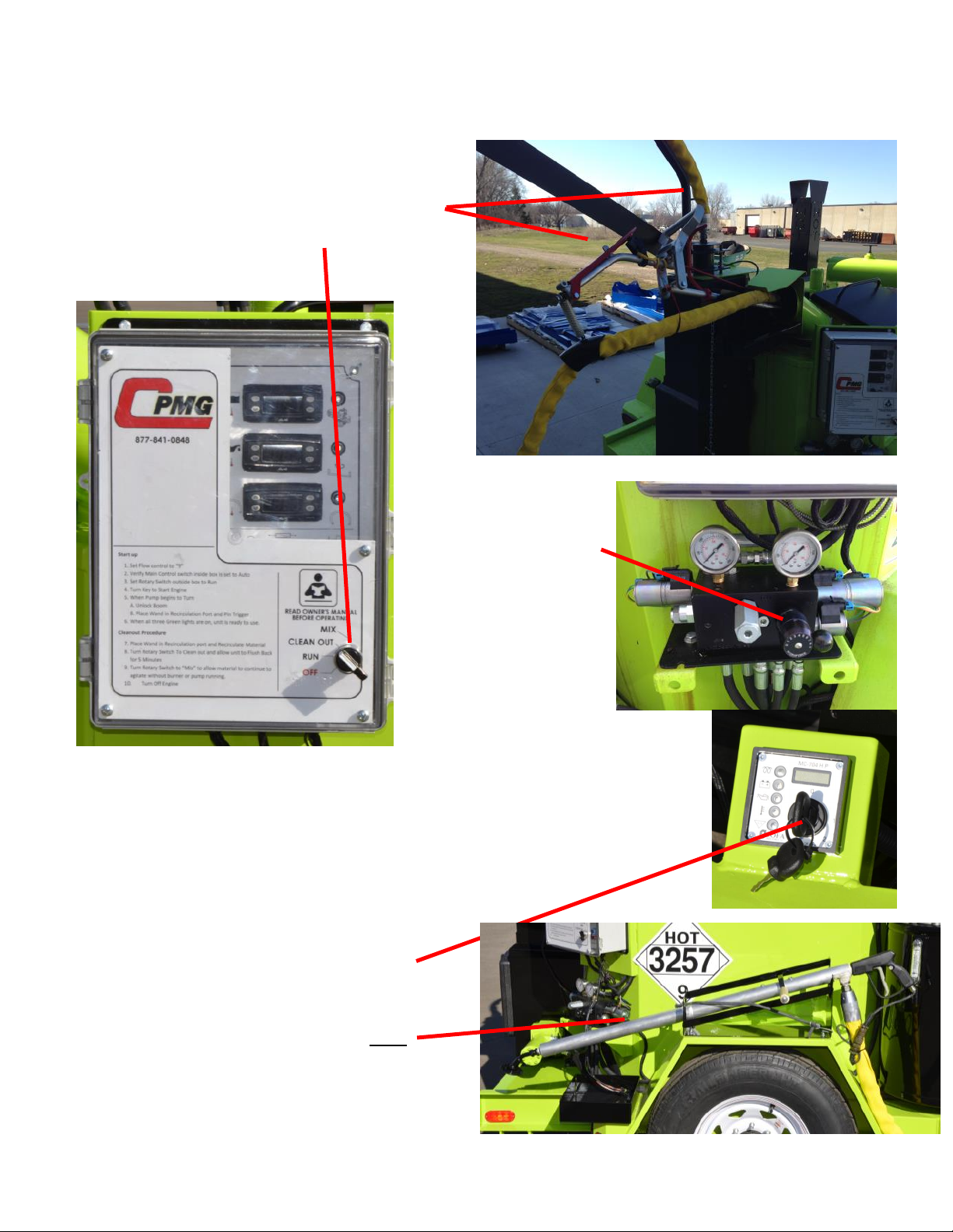
Controls and Their Functions

8
NOTE: Typically it is best to run the M series Magma melter in the Auto control mode. See
page 10 for the start-up procedure. Occasionally you may want to manually override
the presets and control the Melter. Below is an explanation on what each switch in-
side the control box does.
1) Auto/Off/Manual Switch In Auto mode, power will be sent to the rotary switch on the front
cover. When the switch is Off, power is not being sent beyond this switch and the melter will
be unusable. When the Switch is in Manual mode, the four switches below will be energized
and the melter will be under the control of those switches.
2) Controller On/Off Switch: When this switch is on, the three controllers to the right will be
energized and they will be controlling the Diesel burner and the heated hose generator.
3) Material Pump Seal/Off/Clean-out Switch: When this switch is on “Seal”, the pump will be
rotating and material will either be pumping back to tank or to the hose. When the switch is
“Off”, the pump will not be rotating. When the switch is on “Clean-out”, the pump will be rotat-
ing in the reverse directing and will be sucking back any material in the plumbing or the hose.
4) Agitator CCW/Off/CW Switch: This switch controls the rotation of the agitator from counter-
clockwise or Clockwise. If the switch is in the center position, the agitator will not rotate.
5) Low Flow Switch: Occasionally, you will find that the material spits out the wand if the flow
control knob is set to 3 or lower. If this is happening, switch the Auto/Manual switch to Manual
and place the Low flow switch to the “For material flow Lower than 4”. This will make the ma-
terial pump only rotate when the wand trigger is pressed.
6) Pump LED (Green): This LED indicates that the material has reached the preset tempera-
ture and if the unit is running in the Auto mode, the Material pump will be pumping.
7) Agitator LED (Green): This LED indicates that the Heat Transfer Oil has reached the preset
temperature and if the unit is running in the Auto mode, the Agitator will be turning.
8) Heated Hose LED (Green): This LED indicates that the Heated Hose has reached the pre-
set temperature and is ready to use.
9) Diesel Burner LED (Yellow): This LED indicates that the Diesel Burner is on.
10) Heated Hose Fuse: This Slow-blow fuse is protecting the Heated Hose.
11) Heated Hose Generator LED (Yellow): This LED indicates that the Heated Hose Generator
is on.
Controls and Their Functions

9
Controls and Their Functions
1
2
3
4
5
6
7
8
9
10
11
10
1. SETUP:
A) Set Flow control to “9”
B) Set rotary switch to RUN.
2. START ENGINE:
A) Turn key on engine control to “1”
B) Heat glow plugs 3-5 seconds.
C) Turn key to “2”
D) Release when engine starts
Start up

11
3. WAND
When Pump and Agitator Green
Lights are on:
A) Unlock Boom
B) Place wand in port.
4. Ready for Work
When all 3 GREEN lights are on:
A) Set Flow to “0”
B) Pin Wand trigger and
set handle forward
C) Set Flow to
desired level
D) Start Sealing
Start up

12
Automatic Temperature Control Setting
The control system on your CIMLINE “M” series melter has been factory set to run the most
common types of materials. These Materials have an application temperature of 380 deg F.
With some materials, it may be needed to change the controller to achieve the appropriate appli-
cation temperature. To achieve this, open the control box and alter the material controller (top
controller) by following the directions below.
Decrease (DOWN)
Increase (UP)
(A)
1) Press the SET button.
2) SP1 is displayed.
3) Press the SET button.
4) Current Temperature is displayed.
5) Use the arrow buttons to change to the desired temperature.
6) Press the SET button.
7) Let the controller time out. Your controller will now be change and the updates will
be saved.

13
Loading Empty Tank
All material must be clean. Keep all foreign matter out of melting tank.
1) Open the material door (1) and place slab or biscuit (2) on the open door against the
holder (3).
2) Push door to the closed position. DO NOT DROP MATERIAL INTO THE MELTER
WITH DOOR OPEN.
1
2
3
14
Cleanout Procedure
1. SETUP:
A) Place wand in port.
B) Pin wand trigger and set handle forward.
C) Set rotary switch to Clean Out.
D) Set flow to “9”
Hose Clean-out:
Let pump run in reverse for 2 minutes.
Pump Clean-out:
Unpin wand trigger.
Continue running pump in reverse for 2 minutes.
Shut down:
Shut Engine off by turning key to “0”
Set rotary switch to Off.
Move Boom to travel position and lock.
Store wand
Contact material supplier for information on
how to flush out non-reheatable materials.
15
Maintenance
Engine: The operation and life of the engine depends on you and your operator. Do not start
engine until the engine precheck is complete. The engine precheck consists of checking the oil,
the fuel level, the hydraulic oil level and the air filter. The M-1/M-2 Melter Applicator has the op-
tion of (2) different engines. The Isuzu 22.8 H.P. and 40.3 diesel units. For more detailed infor-
mation please refer to the Engine Operator Maintenance Manual and Warranty provided with
your Melter applicator.
NOTE: When breaking in a new Melter, we recommend running the engine for one
hour with no load prior to actual use on the job.
Air cleaner: Due to the dusty conditions that can be created by road work, it is essential to
check the engine air cleaner element daily. Remove element and shake out the accumulated
dust and dirt. Wipe out dirt from inside cover and from housing. Check engine manual for
washing instructions. We recommend stocking replacement filters.
Fuel: Use of high quality detergent oil of API (American Petroleum Institute) service class CC
or CD grade. Select the viscosity based on the air temperature at the time of operation. Check
your engine manual for other recommendations.
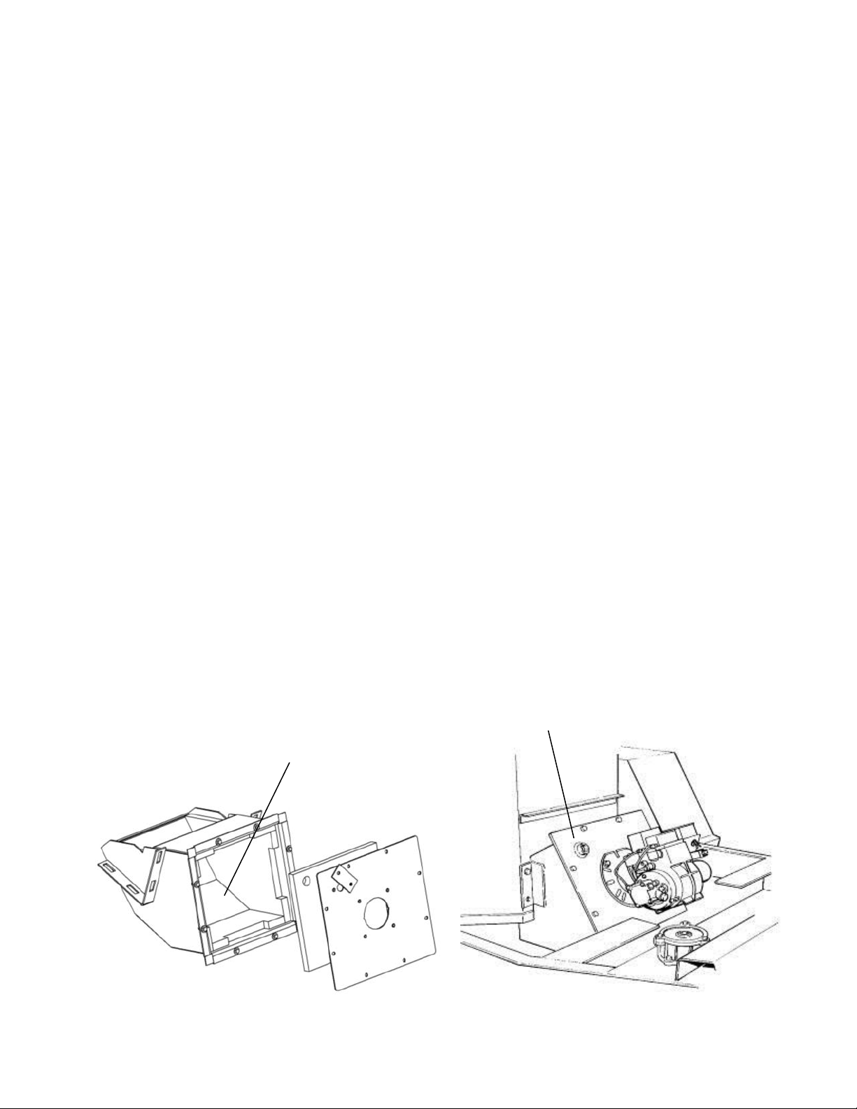
Burner: There are several items that need to be inspected periodically on the burners. These
items include the burner nozzle, electrode and head position, chamber lining (see below) and
the electric eye. Please refer to the burner manual on how to perform each of these operations
in this manual..
After each 200 hours of operation, the chamber lining should be inspected. Remove (8) burner
mount securing bolts (A) and pull out burner and mount. Inspect lining (B) for excessive crack-
ing. Lining cracks are acceptable as long as they are not large enough to allow flame to contact
the combustion chamber walls.
(A)
(B)

16
Maintenance
Maintenance Operation Daily 25 Hrs 100
Hrs 200
Hrs 1000
Hrs Yearly
Check fuel level (add if low) X
Check engine and heat transfer oil (add if low) X
Check hydraulic oil (add if low) X
Check engine air cleaner X
Inspect pre-cleaner X
Cleanout material system X
Inspect sealing hose and cover X
Inspect sealing hose connection X
Drain condensation from air compressor option X
Blow oil cooler on the air compressor option X
Inspect and clean cooling system (Diesel units only X
Inspect material pump packing (adjust if leaking is excessive) X
Check oil level on air compressor option X
Service air cleaner element X
Inspect spark plugs and breaker pts. (Propane units only) X
Inspect burner motor brushes (replace if worn out X
Inspect burner nozzle, electrode & head pos. (adjust if nec.) X
Change engine oil and oil filter X
Grease agitator bearing block (load adapter) X
Inspect fuel filter (replace if dirty) X
Inspect Diesel burner electric eye (clean if dirty) X
Grease wheel bearings X
Inspect chamber lining (replace if excessive cracking) X
Change oil on compressor option X
Change air inlet filter on compressor option X
Inspect starting motor X
Replace hydraulic oil X
Replace hydraulic return filter X
Replace hydraulic suction strainer X
Replace burner nozzle X
Change heat transfer oil X
Change Diesel fuel filter X
Flush radiator and replace fluid (Diesel units only) X
Replace separator on air compressor X
17
Fluid and Components Specifications
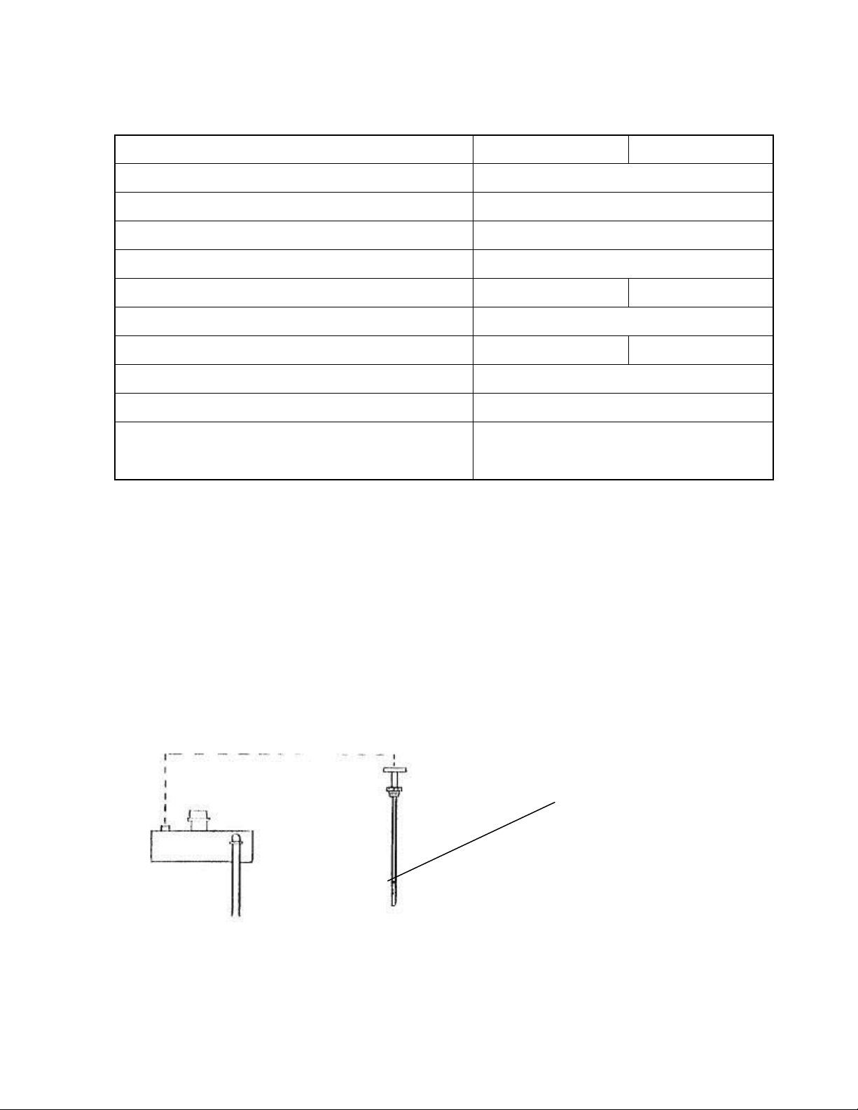
WARNING: Only the oil specified or equal may be used in this system. (Always check
your local and state regulations before disposal).
NOTE: A dipstick (A) is provided for checking oil level when cold.
This is a petroleum based product. We recommend that you do not mix oil brands. Mixing any
oils (Engine oil, transmission fluid, etc.) adversely affects each manufacturers formula.
COLD OIL LEVEL
M1 M2
Hydraulic Reserve Capacity 30 Gallons
Hydraulic Oil Type Conoco MV32 or equiv
Diesel Fuel Capacity 30 Gallons
Diesel Fuel Type ASTM D975 No.2
Heat Transfer Oil Capacity 21 Gal. 26 Gal.
Heat Transfer Oil Type See Specs. On next page.
Agitation Drive Relief Setting 1100 800
Material Pump Drive Relief Setting 800
Material Pump Displacement .11 Gal/Rev
Material Pump Maximum Output Pres-
sure 125 PSI

18
Heat Transfer Oil Specifications
ISO Grade 68 Heat transfer Oil Specification
There are many different types of Heat Transfer Oils on the international marketplace. It is criti-
cal that you use the proper oil to prevent poor performance, oil flashing, or auto-ignition. To
conform to most government bids and to supply a readily available product, CIMLINE typically
uses brands manufactured by Conoco or Phillips 66 that meet the ISO Grade 68 Heat Transfer
Oil specifications listed. To insure maximum safety and performance, we recommend you pur-
chase your oil through CIMLINE.
ISO VG# 68
Pour Point - F 10º F (12º C)
Flash Point - F 485º F (252º C)
Lbs/Gallon 7.27
Viscosity CsT @ 40C 62
IMPORTANT NOTICE!!
The ISO Grade is just a viscosity index (ability to flow/thickness). An ISO Grade 68 oil can be
an engine oil, hydraulic oil, etc. The manufacturer uses different additives to make the oil con-
form to different applications. YOU MUST CLARIFY with the supplier that the oil is to be used
in a heat transfer system to avoid any potential problems. Oil is also available from CIMLINE in
5 and 30 Gallon containers for ship-out.
NOTE: CIMLINE Melter/Applicators include and expansion tank that cools the oil that is ex-
posed to the outside air. When the oil heats up and expands, it flows into the expansion tank.
The tank is cooler since it is not oil jacketed and is surrounded by outside airflow. The only ex-
posure the hot oil has to the atmosphere is through a 3/4" vent/overflow pipe. This is done so
the oil in the tank can run higher than the flash point. Only the lower temperature oil fumes are
exposed to the atmosphere.
FLASH POINT - Test in which an open container of oil is heated until an open flame will flash
when passed over the fumes.
FIRE POINT - Same test as the flash point except the oil is heated until the gasses will start a
fire.
AUTO IGNITION POINT - The point at which fumes will burst into flame when exposed to air.
19
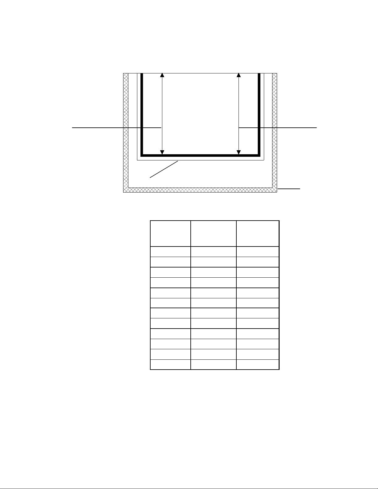
Material Tank Capacity
MATERIAL CAPACITY
(Tank cutaway)
Gallons of material is found by first dividing the tank volume by 231 (# of cubic inches
per gallon of liquid), and then multiplying that number by the number of inches of mate-
rial in the tank. For example, 1052 divided by 231 = 4.55. 4.55 x 2" of material = 9.11.
* Volume of tank in cubic inches for each inch of material.
MATERIAL VAT
M2
9.37 GALLONS
PER INCH
INSULATION
AIR
OIL
M1
6.8 GALLONS PER INCH
Material
Depth
M1
1570 Cubic
Inches
M2
2165 Cubic
Inches
2" 13.6 18.74
4" 27.18 37.48
6" 40.78 56.22
8" 54.37 76.96
10" 67.96 93.7
12" 81.56 112.44
14" 95.15 131.18
16" 108.74 149.92
18" 122.34 168.66
20" 135.93 187.4
22" 149.52 204.14
24" 224.88
20
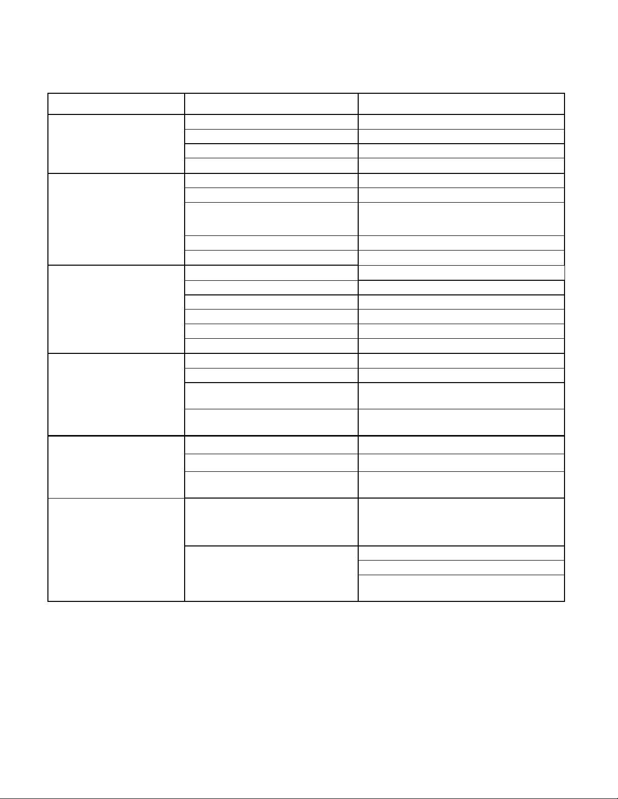
Trouble Shooting Guide
Problem Cause Solution
Burner will not ignite
Fuse burned out. Check fuse
Burner relay inoperative. Check for 12VDC at relay.
Primary control fuse. Check fuse
Thermocouple(s) inoperative Replace thermocouple(s)
Agitator will not rotate
Fuse burned out. Check fuse
Sealant material not hot enough. Allow material to heat longer
Too many biscuits added at one
time. Continue heat up and reverse agitation
to break biscuits free.
Low hydraulic oil level. Check oil Level
Worn agitator motor. Replace Motor
Material pump will not ro-
tate
Fuse burned out. Check fuse
Sealant material not hot enough. Allow material to heat longer
Too much material left in lines Heat plumbing and valve to melt material
Low hydraulic level Check oil level
Foreign object lodged in line Remove foreign object
Pump damaged Repair or replace pump
Material pump rotates but
does not pump material
Pump worn or damaged Repair or replace pump
Pump rotating in wrong direction Reverse pump switch
Pump inlet line plugged
Check matl tank grid and lines for ob-
struction
Too much material left in lines Heat plumbing and valve to melt material
Material heat up time slow
Burner orifice clogged Remove orifice and clean
Heat transfer oil is worn out Check oil level. Replace if necessary
Too much old material on tank Clean material tank
Material recirculates but
will not flow through seal-
ing wand.
Sealing hose valve not completely
closing or worn out Realign valve or replace
Actuator not turning valve
Check Fuse
Check trigger switch
Broken or disconnected wire in the elec-
This manual suits for next models
1
Table of contents
Other CPMG Melting Machine manuals


