CR Remeha QUINTA ACE Series User manual

QUINTA ACE
RANGE

WHAT’S
INSIDE
03 WELCOME TO REMEHA
03 QUINTA ACE RANGE
04 BOILER CONSTRUCTION
06 OPERATING PRINCIPLE
07 TECHNICAL INFORMATION
09 ENGINEERING SPECIFICATION
11 DIMENSIONS AND
CONNECTIONS
13 T YPICAL I NSTALL ATIO N
24 ELECTRICAL INSTALLATION
AND CONTROLS
27 QUINTA ACE 135 AND
160 SPECIFICATIONS
30 FLUE OPTIONS
52 FLUECADE SYSTEM
53 FLUECADE KITS
57 FLUECADE COMPONENTS
61 CASCADE OPTIONS
63 I NSTALL ATION AND
CONFIGURATION
68 BESPOKE RIG SYSTEMS
71 TECHNICAL SUPPORT
71 DECLARATION
OF COMPLIANCE
In the interests of the quality of our products, we strive
constantly to improve them. We therefore reserve
the right to modify the specications and
details provided within this document.

WELCOME TO REMEHA,
THE EXPERT CHOICE
WE LEAD THE WAY IN INNOVATION, RELIABILITY AND EFFICIENCY
FOR ADVANCED COMMERCIAL HEATING SOLUTIONS.
We’re completely focused on commercial heating solutions
and are at the forefront of condensing gas boiler technology
– we don’t manufacture boilers for anyone else.
We invest heavily in research and development which enables
our specialist teams to design high performance products at
every level. From using the latest materials and manufacturing
techniques to meticulously designing and engineering each boiler,
we ensure they’re efcient to specify, install, run and maintain.
All our boilers share the same simple design – so they’re
expandable, adaptable and future-proofed.
We’ve tried to think of everything, so from specication to
blueprint sign-off through to supply and installation, our customer
service and product support is our number one priority.
REMEHA
QUINTA ACE RANGE
The Quinta Ace range is a market-leading
series of versatile, wall-hung condensing
boilers designed for space heating and
indirect hot water production. The Quinta
Ace range is available in 30, 45, 55, 65,
90, 115, 135 and 160kW models.
With their extremely compact design, the Quinta Ace range
can be installed individually or as part of a multi-boiler cascade
or rig system, for exible design and reliable, high-quality
performance. The Quinta Ace range is suitable for use on
sealed systems and open-vented (except the Quinta Ace
135 and 160) installations.
High efciency boiler
up to 97.6% GCV
Higher than average
energy savings
Small dimensions and
lightweight design
Easy to install in smaller spaces;
highly suitable for cascade operation
Low, Class 6 NOx emission levels
of ≤ 36mg/kWh* 0% O2 dry
Low pollutant emissions that
meet ERP regulations and
London plan targets (SPG 2014)
Premix down-ring gas burner
and one-piece cast aluminium
heat exchanger
Clean, trouble-free operation
LED illuminated casing air box,
removable front panel, digital
display, data le for storing
information and remote
signalling options
Improved ease of maintenance
Built-in advanced boiler
control and calorier control:
•
fully modulating
18-100% (5:1)
•
0-10V operation
•
on/off (volt free enable)
Built-in exibility for
easy installation
Extremely compact
cascade packages
Effective space saving solution
for greater design exibility
Quiet operation <52 dB(A) Improved comfort
For use with natural gas
and LPG
Flexible solution to
energy-saving heating
03
QUINTA ACE
RANGE
FEATURES
AND BENEFITS

KEY
1Casing/air box 8Non-return valve 15 Automatic air vent
2Heat exchanger (CH) 9 Combined gas valve unit 16 Hydraulic pressure sensor
3 Flue gas measuring point 10 Return sensor 17 Fan
4Interior light 11 Air intake silencer 18 Supply line
5Flow sensor 12 Instrument box 19 Flue gas discharge pipe
6Ionisation/ignition electrode 13 Siphon 20 Air supply
7Mixing tube 14 Box for the control PCBs (= accessory)
QUINTA ACE
30 - 115 BOILER
CONSTRUCTION

KEY
1Air supply 10 Water pressure sensor 19 Gas valve unit
2Casing/air box 11 Return sensor 20 Venturi
3Interior light 12 PC/laptop connection point 21 Fan
4Flow sensor 13 Control panel 22 Non-return valve
5Adapter 14 On/off switch 23 Air pressure differential switch
6Heat exchanger 15 Condensate collector 24 Automatic air vent
7Temperature sensor for heat exchanger 16 Air inlet silencer 25 Flue gas measuring point
8Ignition transformer 17 Gas pressure measuring point 26 Flue gas outlet
9Inspection hatch for heat exchanger (x2) 18 Control unit (CU-GH)
QUINTA ACE
135 AND 160 BOILER
CONSTRUCTION
05
BOILER
CONSTRUCTION
44..22..1100 CCiirrccuullaattiinngg ppuummpp
ΔΔPPBoiler resistance (mbar)
QQFlow rate (m3/h)
The boiler is supplied without a pump. Take the boiler resistance and
system resistance into account when selecting a pump.
SSeeee
Technical data, page 13.
CCaauuttiioonn
Maximum power consumption may be 300 VA. Use an auxiliary
relay for a pump with greater power.
44..22..1111 CCaalloorriiffiieerr ccoonnnneeccttiioonn
A calorifier can be connected to the boiler. Our range includes various
calorifiers.
IImmppoorrttaanntt
Contact us for more information.
44..22..1122 CCaassccaaddee ssyysstteemm
The boiler is ideally suited for a cascade system. There are a number of
standard solutions available.
IImmppoorrttaanntt
Contact us for more information.
44..33 MMaaiinn ccoommppoonneennttss
11Air supply/flue gas discharge
22Casing/air box
33Interior light
44Flow sensor
55Adapter
66Heat exchanger
77Temperature sensor for heat exchanger
88Ignition transformer
99Inspection hatch for heat exchanger (x2)
1100Water pressure sensor
1111Return sensor
1122PC/laptop connection point
1133Control panel
1144On/off switch
1155Condensate collector
1166Air inlet silencer
1177Gas pressure measuring point
1188Control unit (CU-GH)
1199Gas valve unit
2200Venturi
2211Fan
2222Non-return valve
2233Air pressure differential switch
2244Automatic air vent
2255Flue gas measuring point
2266Flue gas outlet
Fig.3 Water resistance
AD-0000857-02
170
300
250
200
150
100
50
0
012345678910
6,5
[m
3/h]
Q
T = 20 K
Fig.4 Main components
AD-0000218-02
9
8
5
6
7
2
1
4
3
10
12
13
14
11 16
17
18
19
20
21
15
25
24
22
23
26
4 Description of the product
20 7701860 - v.05 - 22012021

QUINTA ACE RANGE
OPERATING PRINCIPLE
The products of combustion in the form of hot ue gases are forced through the heat
exchanger, transferring their heat to the system water. The ue gas temperature is reduced to
approximately 5°C above the temperature of the system return water, then discharged vertically
via the condensate collector, through the 80/125mm (Quinta Ace 30/45) or 100/150mm
(Quinta Ace 55/65/90/115, 135 and 160) combined ue/air connection to atmosphere.
Because of the low ue gas exit temperature, there will be a
vapour cloud formed at the ue gas terminal. If the controls
allow the ow and therefore return temperature to fall below dew
point (55ºC), this water vapour will begin to condense out in the
boiler, transferring its latent heat into the system water, increasing
the output of the boiler without increasing gas consumption.
Any condensate which is able to ow back into the boiler, from
ue lengths greater than one metre, must be discharged via a
condensate collector and drain system tted within one metre of
the boiler ue connection.
Combustion air is drawn into the closed air box by a variable speed
fan, through the air inlet connection from the plant room (open-
ued) or from outside via the concentric ue system (room-sealed).
On the inlet side of the fan is a specially designed Venturi which
is connected to the outlet side of the gas combi-block.
Depending on the demand (under the dictates of ow/return
sensor and other external/internal control inputs), the electronic
control unit directly monitors the volume of gas and air being
delivered to the premix burner. This mixture is initially ignited
by the combined ignition/ionisation probe which then monitors
the state of the ame. Should the ame not ignite or be unstable
within the pre-set safety time cycle, the controls will shut the
boiler down (after ve attempts) requiring manual intervention
to reset the boiler. The digital display will also indicate a
ashing fault code, conrming the reason for the failure.

QUINTA
ACE 30
QUINTA
ACE 45
QUINTA
ACE 55
QUINTA
ACE 65
QUINTA
ACE 90
QUINTA
ACE
115
QUINTA
ACE
135
QUINTA
ACE
160
PERFORMANCE
Nominal heat output central heating
operation @ 80/60°C kW (min-max)* 8.0-29.8 8.0-40.8 11.1-55.3 12.0-61.5 14.1-84.2 18.9-103.9 31.5-128.1 31.5-152.1
Nominal heat output central heating
operation @ 50/30°C kW (min-max)* 9.1-30.9 9.1-42.4 12.3-58.6 13.3-65.0 15.8-89.5 21.2-109.7 34.7-136.1 34.7-161.6
Nominal input (Hi) (min-max) 8.2-30 8.2-41.2 11.3-56.5 12.2-62.0 14.6-86.0 19.6 -107.0 32-131 32-156
EFFICIENCY
SBEM seasonal efciency GCV 97. 62 % 97. 6 4% 96.04% 9 7. 5 8% 95.65% 95.44% 96.12% 95.88%
Efciency – full load 100% NCV 99.4% 9 9.1% 97.8% 99.2% 97.9 % 97.1% 97.8% 97. 5%
Efciency – part load 30% NCV 110.4% 110.6% 108.7% 110.4% 108.1% 108% 108.8% 108.5%
Eco design useful efciency
@ 80/60°C (100% full load) GCV 89.6% 89.3% 88.1% 89.4% 88.2% 87. 5% 88.1% 87.8 %
Eco design useful efciency
@ 50/30°C (30% part load) GCV 99.5% 99.6% 97.9 % 99.5% 97.4% 97.3% 98.0% 97.8%
Energy labelling seasonal space
efciency GCV 94% 94% 92% 94% N/a N/a N/a N/a
ErP efciency rating AAAAN/a N/a N/a N/a
Annual energy consumption kWh 91 125 173 188 N/a N/a N/a N/a
GAS
Standard fuel Natural gas Natural gas Natural gas Natural gas Natural gas Natural gas Natural gas Natural gas
Optional fuel adjustment –
see installation and service manual
LPG
(propane)
LPG
(propane)
LPG
(propane)
LPG
(propane)
LPG
(propane)
LPG
(propane)
LPG
(propane)
LPG
(propane)
Gas consumption NG m3/h 0.9-3.2 0.9-4.4 1.2-6.0 1.3-6.6 1.5-9.1 2.1-11.3 3.4-13.9 3.4-16.5
Max gas consumption LPG m3/h 0.4-1.2 0.4-1.7 0.5-2.3 0.5-2.5 0.9-3.5 0.9-4.4 1.4-5.3 1.4-6.3
Min/max gas inlet pressure NG mbar 17-25 17-25 17-25 17-25 17-25 17-25 17-25 17-25
Min/max gas pressure LPG mbar 37-50 37-50 37-50 37-50 37-50 37-50 37-50 37-50
Gas connection size BSP inches ¾”Male thread
(22mm)
¾”Male thread
(22mm)
¾”Male thread
(22mm)
¾”Male thread
(22mm)
¾”Male thread
(22mm)
¾”Male thread
(22mm)
1” Male thread
(28mm)
1” Male thread
(28mm)
FLUE (CONCENTRIC CONNECTION SUPPLIED AS STANDARD)
Flue diameter mm I/D 80 80 100 100 100 100 100 100
Air inlet diameter mm I/D 125 125 150 150 150 150 150 150
Min/max ue gas mass ow rate kg/h 14-50 14-69 19-93 21-104 28-138 36-178 57-233 57-277
Min/max ue gas temperature °C 30-65 30-67 30-68 30-68 30-68 30-72 32-63 32-66
Max counter pressure Pa 70 150 120 100 160 220 200 200
QUINTA ACE
TECHNICAL INFORMATION
07
OPERATING PRINCIPLE
AND TECHNICAL INFORMATION

QUINTA
ACE 30
QUINTA
ACE 45
QUINTA
ACE 55
QUINTA
ACE 65
QUINTA
ACE 90
QUINTA
ACE
115
QUINTA
ACE
135
QUINTA
ACE
160
HYDRAULICS
Water content litres 4.3 4.3 6.4 6.4 9.4 9.4 17.0 17.0
Resistance @ 15°C ∆T mbar 124 203 231 290 272 444 224 302
Hydraulic resistance @ 20°C ∆T mbar 70 114 130 163 153 250 126 170
Nominal ow rate @ 15°C ∆T l/s 0.48 0.65 0.88 0.97 1.34 1.66 2.04 2.43
Nominal ow rate @ 20°C ∆T l/s 0.36 0.49 0.66 0.74 1.01 1.24 1.53 1.82
Condensate connection 32mm 32mm 32mm 32mm 32mm 32mm 32mm 32mm
Connection size BSP (32mm) 1¼” Male
thread (32mm)
1¼” Male
thread (32mm)
1¼” Male
thread (32mm)
1¼” Male
thread (32mm)
1¼” Male
thread (32mm)
1¼” Male
thread (32mm)
1¼” Male
thread (32mm)
1¼” Male
thread (32mm)
Standard operating temperature** °C 20-90 20-90 20-90 20-90 20-90 20-90 20-90 20-90
Max operating temperature °C 90 90 90 90 90 90 90 90
High limit temperature °C 110 110 110 110 110 110 110 110
Max water operating pressure bar 44444444
Min water operating pressure bar 0.8 0.8 0.8 0.8 0.8 0.8 0.8 0.8
Min operating pressure bar (OV)** 0.3 o/v 0.3 o/v 0.3 o/v 0.3 o/v 0.3 o/v 0.5 o/v N/a N/a
GENERAL
Total weight (including packaging) kg 60.5 60.5 66.5 66.5 76.5 76.5 147 147
Min mounting weight without
front panel kg 50 50 56 56 65 65 123
123
Dimension mm (WxHxD) 500x750x500 500x750x500 500x750x500 500x750x500 500x750x500 500x750x500 600x1045x602 600x1045x602
NOx (Dry, 0% O2) NCV - EN15502
(Class 6) Mg/kWh 33 33 36 36 29 33 24 36
Noise levels dB(A) at 1 metre 38.3 45.1 46.7 46.7 51.6 51.1 59.5 59.5
Eco design sound power levels LWA
indoors dB 46 53 55 55 60 59 68 68
Standby heat loss kW 0.101 0.101 0.110 0.110 0.123 0.123 0.191 0.191
ELECTRICAL
Nominal power supply 230v x 1ph
x 50hz
230v x 1ph
x 50hz
230v x 1ph
x 50hz
230v x 1ph
x 50hz
230v x 1ph
x 50hz
230v x 1ph
x 50hz
230v x 1ph
x 50hz
230v x 1ph
x 50hz
Power consumption w 19-40 20-75 38-100 26-89 26-114 32-182 47-199 47-275
Modulating input v dc 0-10 0-10 0-10 0-10 0-10 0-10 0-10 0-10
Fuse rating amps 2.5 2.5 2.5 2.5 2.5 2.5 6.3 6.3
Controls voltage 24 (max 4va) 24 (max 4va) 24 (max 4va) 24 (max 4va) 24 (max 4va) 24 (max 4va) 24 (max 4va) 24 (max 4va)
Electrical protection index VAC X4D X4D X4D X4D X4D X4D X1B X1B
QUINTA ACE
TECHNICAL INFORMATION
*Gas consumption based on lower heating value under standard heating conditions: T=288.15K, p=1013.25mbar. Gag 30.33, G25 29.25, G31 88.00 MJ/m3
.
**Open vented option maximum operating temperature 75°C.

SUGGESTED
ENGINEERING SPECIFICATION
QUINTA ACE
CONSTRUCTION
The boiler will be a wall-hung type condensing boiler which
may also be installed free-standing on a suitable frame.
The single piece, cast aluminium heat exchanger and other
major components are contained within a sealed air box.
The boiler casing will be complete with a removable front
section for maintenance purposes. Electrical and electronic
controls will be contained within the instrument panel
mounted in the drop-down lower front panel and also the
electrical housing mounted on the inside right hand panel.
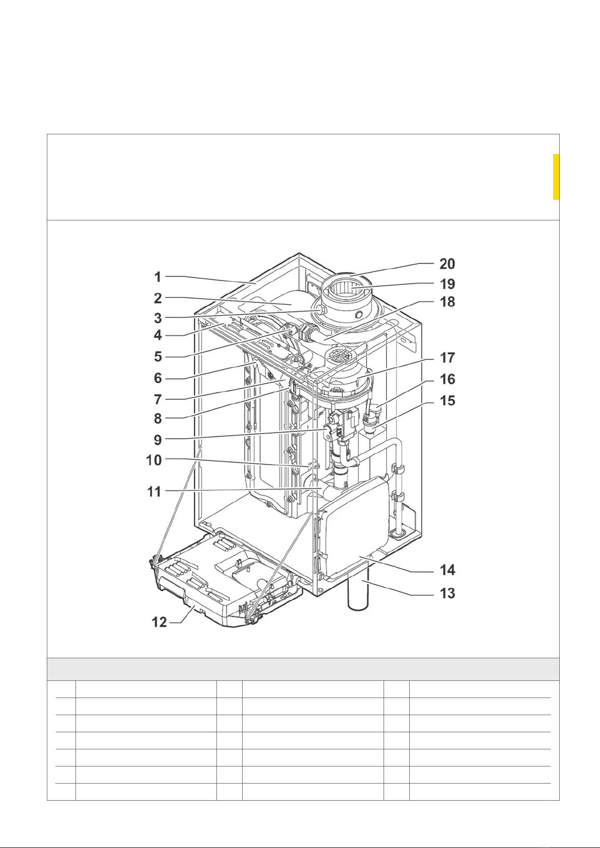
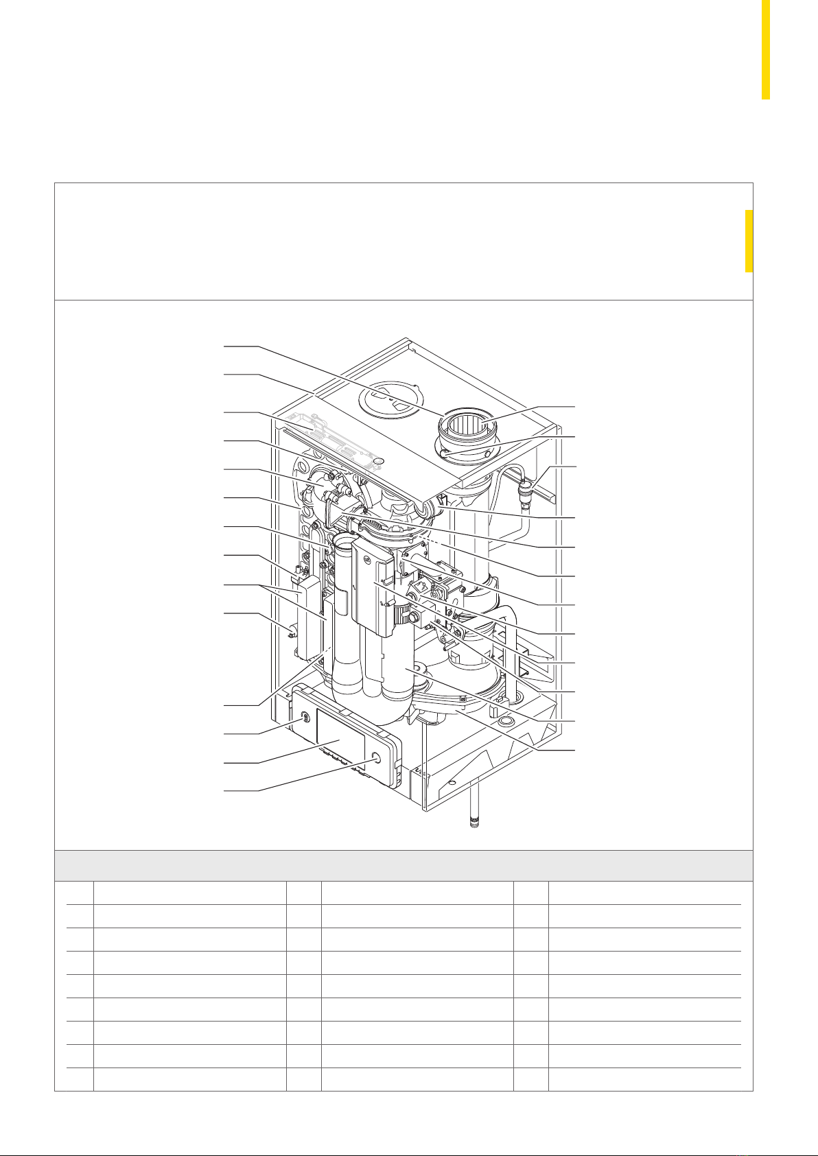
HYDRAULIC, GAS AND
FLUE CONNECTIONS
The combined ue gas outlet and combustion air inlet will be
mounted on the top of the boiler, with the ow, return, gas and
condensate connections located at the bottom. The boiler will be
suitable for room-sealed or open-ue applications. The boiler will
be designed for central heating and indirect hot water production
up to four bar. The boiler will be suitable for use on sealed
systems and open-vented installations.
OPER ATION
The boiler will be complete with a modulating control system
that limits the maximum difference in temperature between the
heating ow and return and the maximum speed at which the
ow temperature increases. The boiler will be complete with a
pre-mix burner (NG or LPG) with the gas/air ratio control system
controlled internally. An intelligent, advanced boiler control will
continuously monitor the boiler conditions, varying the heat
output to suit the system load. The control will be able to react to
external negative inuences in the rest of the system (ow rates
and air/gas supply problems), maintaining boiler output for as
long as possible without resorting to a lockout condition. Should
a negative effect happen in the system, the boiler will reduce its
output and/or shut down (shut-off mode), awaiting the negative
conditions to return to normal before re-starting. The control
cannot override the standard ame safety controls. Standard
frost protection will activate below 7°C with stage one activating
system/shunt pump. Stage two will activate below 3°C with
boiler switching on to 10°C ow.
CONTROLS
The boiler will include an “e-Smart” control platform offering
improved connectivity using the integral MK3 controller.
The controls package will allow the actual and set values to
be read and adjusted on the built-in digital display, which also
provides normal operating and fault code indication. The controls
will come as standard with the following inputs/outputs:
• 0-10V input (ow temperature or output percentage control)
•DHW temperature input
•high limit lock out
•safety/shutdown/release input (blocking)
•low water protection
•outside sensor (optional)
•external shunt pump control
•service report output
•external system pump control
•fault alarm output
•DHW 3-port valve control or pump
•OpenTherm, R-Bus & Volt Free Enable connection.
FEATURES
•Low, Class 6 NOx ≤36mg/kWh
•Fully modulating
•Quiet operation <52dB(A)
•LED illuminated interior (integral battery)
• Data le for storing fault/run info
•Automatic maintenance warning
•PC connection
•ErP compliant
•Relay kit (optional)
•Premix burner
• In build passive ue gas non-return valve.
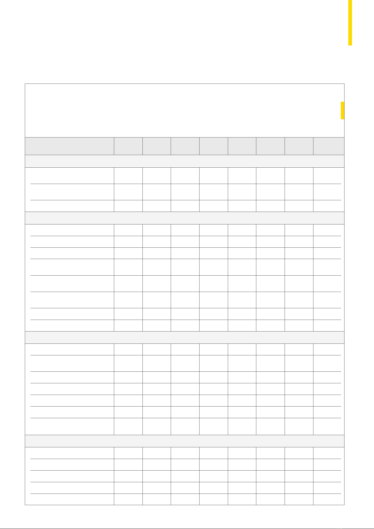
The Quinta Ace 30/45/55/65/90/115 boilers conform with
the following EC-directives:
GAR (EU) 2016/426 to EN 15502-1:2012 +A1:2015 and
EN 15502-2-1:2012 +A1:2016
BED 92/42/EEC to EN 15502-1:2012 +A1:2015 and
EN 15502-2-1:2012 +A1: 2016
EMC 2014/30/EU to EN 55014-1:2017, EN 61000-3-2:2014
and EN 61000-3-3:2013
LVD 2014/35/EU to EN60335-2-102:2016, EN60335-1:2012
ErP 2009/125/EC
CE Certication Remeha Quinta Ace 30/45/55/65/90/115
PIN: 0063CS3928
09
TECHNICAL INFORMATION
AND ENGINEERING SPECIFICATION

QUINTA ACE 135 AND 160
CONSTRUCTION
The boiler will be a wall-hung type condensing boiler
which may also be installed free-standing on a suitable frame.
The single piece, cast aluminium heat exchanger and other
major components are contained within a sealed air box.
The boiler casing shall be complete with a removable front
section for maintenance purposes. Electrical and electronic
controls will be contained within the instrument panel mounted
in the drop-down lower front panel. This control panel will
be able to be removed and wall-mounted if required.
HYDRAULIC, GAS AND
FLUE CONNECTIONS
The combined ue gas outlet and combustion air inlet will be
mounted on the top of the boiler, with the ow, return, gas and
condensate connections located at the bottom. The boiler will be
suitable for room-sealed or open-ue applications. The boiler will
be designed for central heating and indirect hot water production
up to four bar. The boiler will only be suitable for use on sealed
hydraulic systems.
OPER ATION
The boiler will be complete with a modulating control system
that limits the maximum difference in temperature between the
heating ow and return and the maximum speed at which the
ow temperature increases. The boiler will be complete with a
pre-mix burner with the gas/air ratio control system controlled
internally. An intelligent, advanced boiler control will continuously
monitor the boiler conditions, varying the heat output to suit the
system load. The control will be able to react to external negative
inuences in the rest of the system (ow rates and air/gas supply
problems), maintaining boiler output for as long as possible
without resorting to a lockout condition. Should a negative effect
happen in the system the boiler will reduce its output and/or
shut down (shut-off mode), awaiting the negative conditions to
return to normal before re-starting. The control cannot override
the standard ame safety controls. Standard frost protection
will activate below 7°C with stage one activating system/shunt
pump. Stage two will activate below 3°C with boiler switching
on to 10°C ow.
CONTROLS
The boiler will include an “e-Smart” control platform offering
improved connectivity using the integral MK3 controller.
The controls package will allow the actual and set values to
be read and adjusted on the built-in digital display which also
provides normal operating and fault code indication. The controls
will come as standard with the following inputs/outputs:
• 0-10V input (ow temperature or output percentage control)
•DHW temperature input
•high limit lock out
•safety/shutdown/release input (blocking)
•low water protection
•outside sensor (optional)
•external shunt pump control
•service report output
•external system pump control
•fault alarm output
•DHW 3-port valve control or pump
•Open Therm & Volt Free enable.
FEATURES
•Low, Class 6 NOx</ = 36mg/kWh
•Fully modulating
•Quiet operation <60dB(A)
•LED illuminated interior (integral battery)
• Data le for storing fault/run info
•Automatic maintenance warning
•PC connection
•ErP compliant
•Relay kit (optional)
•Premix burner
• In build passive ue gas non-return valve.
The Quinta Ace 160 boiler is in conformity with the following
EC-directives:
GAR (EU) 2016/426 to EN 15502-1:2012 + A1:2015 and EN
15502-2-1:2012 +A1:2016
BED 92/42/EEC to EN 15502-1:2012 + A1:2015 and EN
15502-2-1:2012 +A1:2016
EMC 2014/30/EU to EN 55014-1:2007 + A1:2009 + A2:2011,
EN 55014-2: 2015, EN 61000-3-2:2014 and EN 61000-3-3:2013
LVD 2014/35/EU to EN 60335-2-102:2016
ErP 2009/125/EC
CE Certication Remeha Quinta Ace 160 PIN: 0063CQ3781

The complete range of Quinta Ace 30, 45, 55, 65, 90 and 115 boilers
has a compact design of h750 x w500 x d500mm.
KEY
Connection of the combustion
gas exhaust pipe;
• Ø 80mm (≤45kW)
• Ø 100mm (≥55kW)
Connection of the air intake pipe;
• Ø 125mm (≤45kW)
• Ø 150mm (≤55kW)
Siphon connection bush
Heating circuit return;
1¼” Male thread (32mm)
Gas connection; ¾” Male thread (22mm)
Heating circuit ow;
1¼” Male thread (32mm)
QUINTA ACE
DIMENSIONS AND
CONNECTIONS
11
ENGINEERING SPECIFICATION
DIMENSIONS AND CONNECTIONS

KEY
Flue gas outlet connection; Ø 100mm
Air supply connection; Ø 150mm
Siphon connection 32mm
Flow connection;
1¼” Male thread (32mm)
Return connection;
1¼” Male thread (32mm)
Gas connection; 1” Male thread (28mm)
QUINTA ACE
135 AND 160
DIMENSIONS AND
CONNECTIONS
425
300
240
110
1045
600
143
602
226
80

Single Quinta Ace 30, 45, 55, 65, 90 and 115 boilers, heating only.
QUINTA ACE
TYPICAL
INSTALL ATION
Note: Control PCBs are shown diagrammatically. Earths are omitted for clarity.
13
TYPICAL INSTALLATIONS
The schematics presented within this document are generic and therefore are not
representative of a design for a specic site application. It is the responsibility of the specier
and the installer to ensure that all system components are appropriately sized for the specic

Single Quinta Ace 30, 45, 55, 65, 90 and 115 boilers, heating
and domestic hot water, using a simple ‘S’ plan.
QUINTA ACE
TYPICAL
INSTALL ATION
Note: Control PCBs are shown diagrammatically. Some earths and neutrals are omitted for clarity.

Single Quinta Ace 30, 45, 55, 65, 90 and 115 boilers, heating
only with low loss header.
QUINTA ACE
TYPICAL
INSTALL ATION
Time/temp
control
230v supply
Pump SH1
Condensate
Gas
Pump PM1
Flow
Return
Time/temp control
(volt free)
Pump PM1
Factory fitted
fly lead Shunt pump SH1
Alternative
0-10v control
BR BL GN/YW
BR BL GN/YW
132
X1
Main control PCB PCB - SCU - S02 PCB - SCU - X01 PCB - IF 01
PUMP
X81
StatusStatus StatusEgvPump hws/3wv
OT BL RL Tout Tdhw
15
TYPICAL
INSTALL ATION
Note: Control PCBs are shown diagrammatically. Earths are omitted for clarity.

Single Quinta Ace boiler, heating with priority hot water using a low
loss header. 3-way valve DHW priority Quinta Ace 30/45/55/65 only.
QUINTA ACE
TYPICAL
INSTALL ATION
Note: When using the Remeha supplied low loss header and pump kit and the DHW diverting valve or primary pump kit, the calorier
must be sited within 3m of the boiler. In both cases, the DHW cylinder must be a high recovery unit capable of accepting the full or
adjusted DHW output of the boiler used. Control PCBs are shown diagrammatically. Earths are omitted for clarity.

Single Quinta Ace boiler, heating with priority hot water using a low loss header.
Pumped option, DHW priority can be used on all Quinta Ace 30, 45, 55, 65, 90
and 115 (see page 21).
QUINTA ACE
TYPICAL
INSTALL ATION
17
TYPICAL
INSTALL ATION
Note: When using the Remeha supplied low loss header and pump kit and the DHW diverting valve or primary pump kit, the calorier
must be sited within 3m of the boiler. In both cases, the DHW cylinder must be a high recovery unit capable of accepting the full or
adjusted DHW output of the boiler used. Control PCBs are shown diagrammatically. Earths are omitted for clarity.

Single Quinta Ace 30, 45, 55, 65, 90 and 115 boilers, heating only,
room compensation using iSense controls.
QUINTA ACE
TYPICAL
INSTALL ATION
Status Status Status
BR BL GN/YW
BR BL GN/YW
132
OT BL RL Tout Tdhw
X1
Main control PCB
Return
Flow
Gas
Condensate
230v supply
100m Max
Pump PM1
1.6M
Suggested height in room
Normal position for the iSense controller
mounted in reference room within the building
(room compensation)
Pump PM1
on/off or
modulating controls
O T
PCB - SCU - S02 PCB - SCU - X01 PCB - IF 01
Factory fitted
supply lead to
be connected
to a 230v fused
spur for boiler
permanent supply
PUMP
X81
Egvhws/3wvPump
Note: Control PCBs are shown diagrammatically. Earths are omitted for clarity.

Single Quinta Ace 30, 45, 55, 65, 90 and 115 boilers, heating only, weather
compensation using the iSense controls.
QUINTA ACE
TYPICAL
INSTALL ATION
Status Status Status
BR BL GN/YW
BR BL GN/YW
132
OT BL RL Tout Tdhw
Main control PCB PCB - SCU - S02 PCB - SCU - X01 PCB - IF 01
Factory fitted
supply lead to
be connected
to a 230v fused
spur for boiler
permanent supply
PUMP
X81
Egvhws/3wvPump
1.6M
Suggested height in room
Normal position for the controller mounted
in reference room within the building
iSense can be fitted in the boiler if
used for weather compensation only
100m Max
Condensate
Gas
Flow
Return
100m Max
Outside sensor
on North
facing wall Pump PM1
230v supply
X1
Pump PM1
Outside sensor
on/off or
modulating controls
OT
Note: Control PCBs are shown diagrammatically. Earths are omitted for clarity.
19
TYPICAL
INSTALL ATION

Single Quinta Ace boiler, heating and hot water priority.
Heating room or outside weather compensated with
iSense controls. 3-way valve hot water priority Quinta
Ace 30/45/55/65 only.
QUINTA ACE
TYPICAL
INSTALL ATION
Note: When using the Remeha supplied low loss header and pump kit and the DHW diverting valve or primary pump kit, the calorier
must be sited within 3m of the boiler. In both cases, the DHW cylinder must be a high recovery unit capable of accepting the full or
adjusted DHW output of the boiler used. Control PCBs are shown diagrammatically. Earths are omitted for clarity.
This manual suits for next models
8
Table of contents
Other CR Remeha Boiler manuals
Popular Boiler manuals by other brands

ECR International
ECR International COMBI 115 Installation, operation and maintenance manual

VOKERA
VOKERA Pinnacle Installation & servicing manual

UNMAK
UNMAK technopel Installation and user manual

Bosch
Bosch GB125 Product Information Notice

Baxi
Baxi PRIME Series installation manual

IDEAL
IDEAL imax W45 Installation and Servicing Manual

Beretta
Beretta NOVELLA 55 RAI installation manual

Baxi
Baxi Combi 130 HE User operating instructions

Navien
Navien NFC-175 Service manual

Harsco Industrial
Harsco Industrial SC-2000 Installation & owner's manual

Ideal Boilers
Ideal Boilers VOGUE MAX COMBI 32 user guide

Laars
Laars MINI-THERM JX Series Installation and operation instructions