Craftfull CR-196-10E User manual

C
ull
CR-196-10E
Omiwebo Miweba GmbH
Gewerbepark 20
96149 Breitengüßbach
www.miweba.de
ku
s
rv
c
1
USER MANUAL
21 inch Gasoline Lawnmower
Self-propelled: HG53SMH-XP200
Gasoline Engine:ZONGSHEN-XP200, 196cc, OHV, Single Cylinder, 4 Strokes
CAUTION: Before any use read carefully the user manual which has been purposely drawn
up to provide you with all the necessary information for proper use, in
compliance with basic safety requirements.
Caution: Read carefully the manual before use.
Caution: Keep other people well away from the danger area.
Caution: Risk of hand and feet injuries.
Caution: Emission of toxic gas, do not use
the mower in a close area or not well ventilated.
Caution: hot surfaces.
Caution: Before carrying out any operation stop the engine and
disconnect the spark plug cap.
Caution: Never fill up the fuel tank while the engine is running.
IMPORTANT: Read with care the security requirements included in the engine manual
before the first use of the engine.
2

1-DESCRIPION
SUMMARY:
1/ DESCRIPTION
2/ ASSEMBLY OF GRASS CATCHER/DEFLECTOR
3/ HANDLE ASSEMBLY
4/
ADJUSTMENT OF CUTTING HEIGHT
5/
SAFETY PRECAUTIONS
6/
OPERATION
7/
GEAR BOX
8/
SAFETY RULES
9/
MAINTENANCE
10/
EXPLODING VIEW
11/
WARRANTY
1 Engine control bar 2 Self-propelled 3 Superior handle 4 Inferior handle
5 Engine 6 Deck 7 Tool box 8Throttle control
Side-discharge Grass-guiding Board
Side-Closing Board
SCHNELLAUFBAU
12/
3

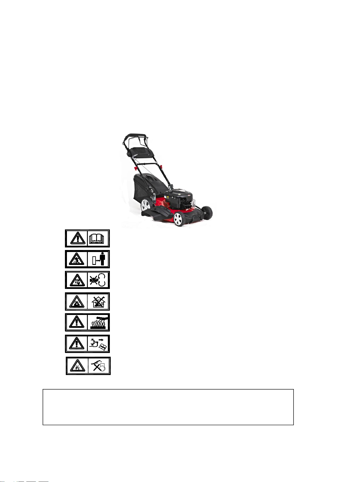
2-4 IN 1 FUNCTION
Mulching:
Close the Side-Closing Board and insert the Mulcher Guard (Fig C)
Rear discharge with grass collection:
Take out the Mulcher Guard (Fig C) and place the grass catcher at its place. fig B
Rear discharge without grass collection:
Take out the Mulcher Guard (Fig C) and close the Side-Closing Board.
Mulcher Guard
4
Side discharge:
Take out the Mulcher Guard (Fig C) and Side-discharge Grass-guiding Board (Fig D)
Fig Pictures
B
C
D
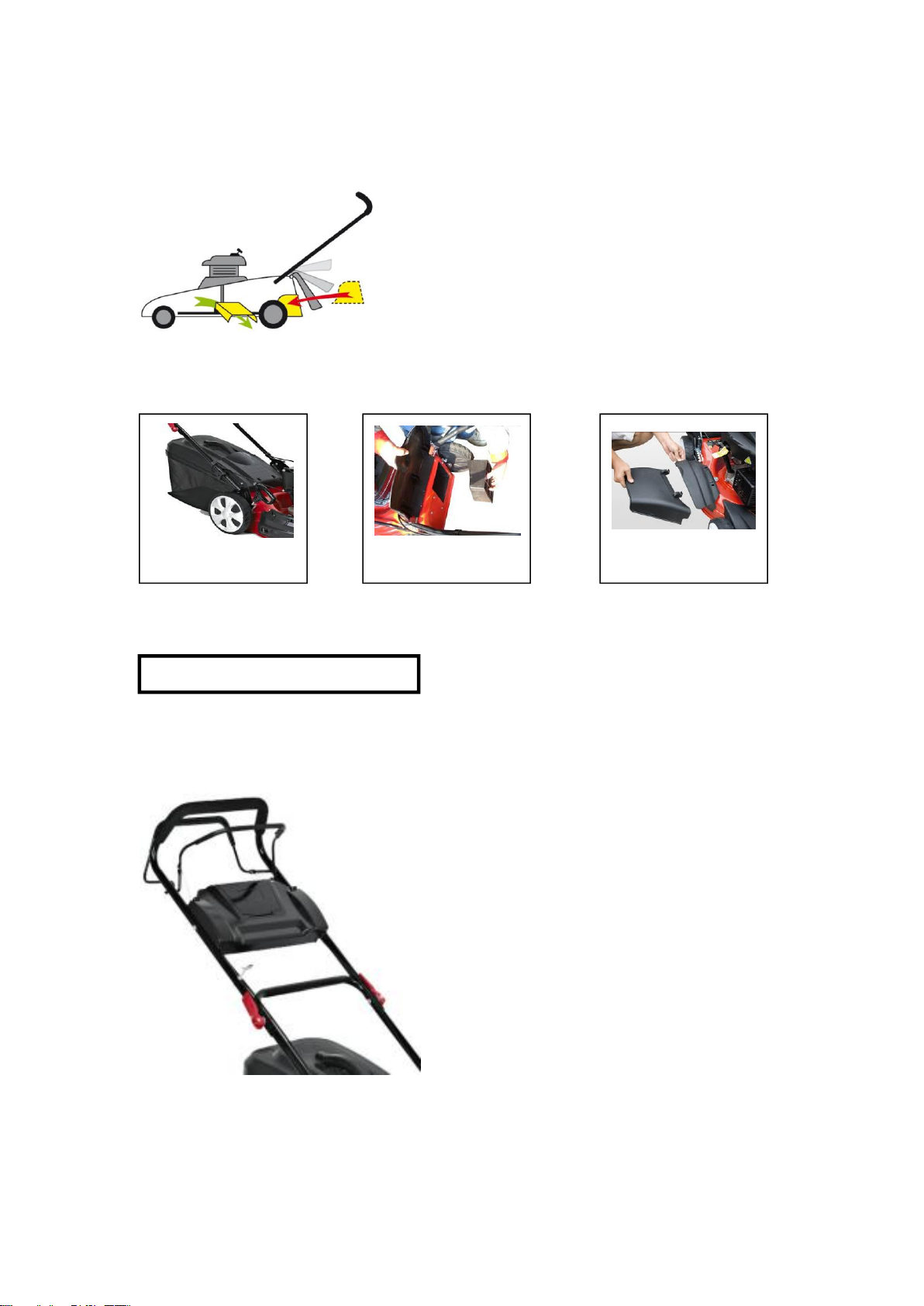
3-ASSEMBLY OF THE HANDLE
Open out the handle and screw the handles parts with the two screws and plastic nuts. Put the
recoil starter on the right of the handle and fix the cable with the plastic collar.
Introduce the rope of the recoil starter handle on its support guide rope.
5

3.1
2.2
2.3
2.4
4 X
5
1
2
3
4
Rad zusammenbauen
Installation der unteren Armlehne
Fixierung der oberen
Armlehne und der
unteren Armlehne
Fixierung der Verkabelung
Klingenmontage
2.1
3.2
Die Schrauben
der Klinge
müssen mit über
40 Newton fest
angezogen
werden.
Installation der Handlaufverkleidung
Einfädeln des Seils
4-SCHNELLAUFBAU
6

5A
B
C
1
2
6
7
Batterieinstallation
5Montagezubehör
Grassfangkorb
Mulcheinsatz
Seitenauswurf
Kabelverbindung für Batterie und Netzschalter
7
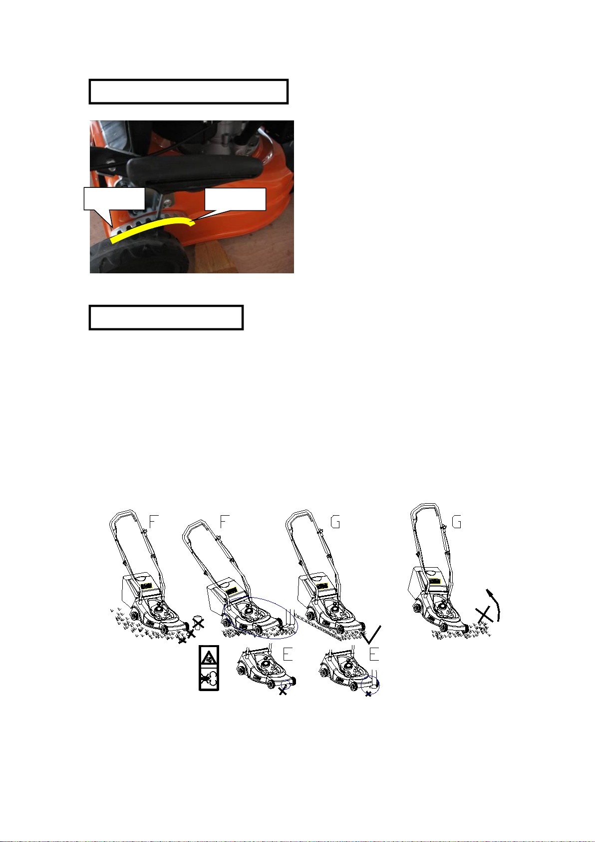
5-CUTTING HEIGHT AJUSTMENTS
6-SAFETY PRECAUTIONS
a) Always use the lawnmower with the grass catcher or/ and the deflector in position.
b) Stop the engine before emptying the grass catcher or before you change the cutting
height.
c) While the engine is running, never introduce your hands or feet under the lawnmower or
under the grass ejection area. fig E
d) Before mowing, remove all foreign objects from the lawn, which maybe thrown by the
machine. fig F
e) Keep children and other people and domestic animals at a safe distance when the
lawnmower is in use.
f) Never lift the mower while starting the engine. fig G
Lowest Level
Highest Level
8

7-OPERATION
Before using the machine you must read the Engine instruction book.
Engine delivered without oil: add 0.6liter of oil before
starting the engine.
ENGINE STARTING:
Once the machine has been set up properly, start the engine as follow:
a) Put the lever on the START position or 。
b) Take the flame out (N○3) and maintain it against the superior handle, pull on the recoil starter
handle until you can feel resistance and then pull harshly.
c) Put the lever on RUN position or 。
If the machine is equipped with electric start, press the "START" or "POWER" button or turn
the key switch to the "start" position to use the electric start. Typically, electric start engines can
also be pull started.
Blade is in action as soon as engine started. While the machine is working maintain the
security handle (3) in working position. The engine will stop as soon as you release the engine
control bar.
9
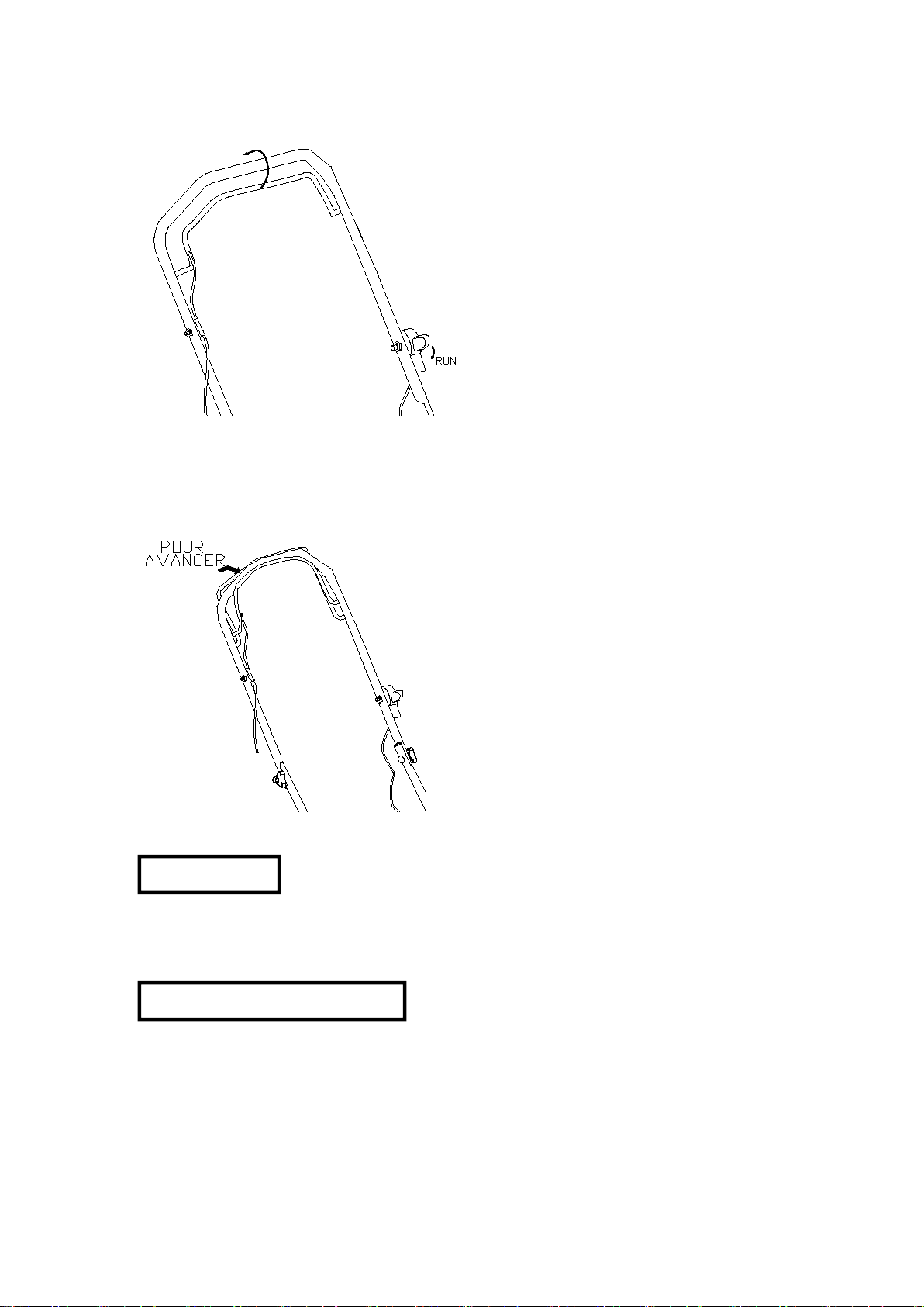
8-GEAR BOX
9-SECURITY MEASURESURES
DEMARRAGE
FOR THE SELF PROPELLED MOWER HG53SMH-XP200
To engage the self-propelled system, pull on the inferior lever of the handle and maintain it
engaged together with the brake lever. fig H
Control frequently the self-propelled system. Polish the gear in the wheels and put grease on them.
Do the same control on the ball bearing if any.
General conditions of use.
1. This machine is to be used exclusively for cutting natural grass. Never use the mower for
other purposes. Any other utilization can involve danger for your safety and can involve
damage to the mower.
2. Persons under 16 years of age and persons who are not familiar with the user instructions
must not use the mower.
10

3. The user is responsible of the safety of other people in the working area. Keep children and
domestic animals at a safe distance while the mower is in use.
4. Before mowing, remove all foreign object from the lawn which may be thrown by the
machine, stay alert for any foreign objects which may have been missed.
USING INSTRUCTIONS
1. Check that all nuts, bolts and screws are well tightened.
2. Before mowing place the grass catcher in its position.
3. Before mowing make sure that the blade and the blade fixing screw are securely fastened.
When cutting edges require resharpening, this must be done evenly on both sides so as to
prevent any imbalance. If the blade is damaged, it must be replace.
4. When mowing always wear a long trousers and strong footwear.
5. Do not run the engine in an enclosed and/or poorly ventilated area, where gas of the engine
contains carbon monoxide, which are dangerous for your health.
6. Work only when there is sufficient light.
7. Do not use the lawnmower when it is raining or when the grass is wet.
8. Particular precautions must be taken while mowing on slopes or downing stretches. Mow
across the face of slopes, never down or up.
9. Turn off the engine if you must leave the lawnmower unattended, displace the lawnmower or
incline it.
10. Never lift the rear of the mower while starting the engine and never place your hands and feet
underneath the deck or into the rear discharge chute while the engine is running.
11. Never change in any way the rated speed of the engine.
12. On the self-propelled mowers, disconnect the self-propelled system before starting the engine.
13. Never lift or carry the mower while the engine is running.
14. Stop the engine and remove the spark plug cover in these cases:
- Before any operation under the deck or the grass rear discharge chute.
- Before any maintenance, repairing or checking operations.
- Before carrying, lifting or removing the mower.
- If you leave the mower unattended or changing the cutting height.
- To remove and emptying the grass catcher.
- After hitting a foreign object, stop the engine and check thoroughly the mower in order
to see if it is damage. Bring the mower in a agreed service station to do the repairing if
necessary. WARNING: After you stopped the engine the blade is still in
motion during a few seconds.
- If the mower vibrates in an abnormal way, find the reasons why, and take your mower to
an agreed service station.
- Check regularly that bolts, nuts and screw are secularly tightening for a safe use of the
mower.
15. WARNING:GASOLINE IS HIGHLY INFLAMMABLE.
- Keep gasoline in a jerry can specially made for this purpose.
- Fill up the tank with a funnel, do the operation outside. Do not smoke. Do not use mobile
phone.
- Fill up with gasoline and oil before staring the engine. Never open the cap of the fuel
11
10-MAINTENANC
tank to add gasoline while the engine is running or still hot.
- Do not start the engine if there is some gasoline spread around, take the mower away
from the one where gasoline have been split and avoid any contact from a hot source as
long as the split gasoline is completely eva0porated.
- Tighten the fuel tank cap and close tightly the jerry can cap.
Maintenance and storage
WARNING: Stop the engine and unplug the spark plug before an
repairing or maintenance operations
- Make sure that all nuts, bolts and screws are kept well tightened to kee0p the lawnmower
in a safe operating condition.
- Never store the lawnmower with a tank with gasoline in an enclosed area where gasoline
fumes could reach a strong heat source or a flame. Allow the engine to cool down before
you store your lawnmower in any storage place.
- In order to reduce any risk of fire, clean the lawnmower and in particularly the engine,
the muffler, the fuel tank. Suppress all grass traces or leaves or excess of grease.
- Check frequently the condition of the deflector and the grass catcher, replace them if the
are damage.
- In case of drain oil of the tank before winter, do this operation outside.
- Wear thick gloves for the mounting and the sharpening of the blade. Be sure that the
blade is always well balance.
WARNING: stop the engine and unplug the spark plug before
any repairing or maintenance operations.
:Stop the engine and unplug the spark plug before any repairing or maintenance operations.
- For four strokes engine read carefully the maintenance engine manual. Check regularly
the oil level and add some oil or replace it if necessary.
- Frequently check the lawnmower and ensure that all grass deposits are removed from
beneath the deck.
- Lubricate regularly the wheel axle and the bearings with grease.
- Check often the blade, in order to obtain a clean work the blade should always be sharp
and well balance.
- At regularly intervals check the tightening of all bolts and screws. Wear off or badly
tightening nuts and bolts can involve some important damages to the engine or the frame.
- If the blade hits violently an obstacle, stop the lawnmower and bring it to agreed service
station.
12

THE BLADE: the blade is made of pressed steel, in order to obtain a clean work sharpen the blade
frequently, around every 25hours of work. Be sure that the blade is always well balance, introduce
a small iron axle(φ2 or φ3 mm) in the central hole of the blade, it should stay horizontal.
If the blade does not stay horizontal balance it by taking off some metal on the side, which is
down.
YOU MUST ONLY USE THE MANUFACTURER BALDE IT SHOULD BE
REFERENCED AND WEAR THE MANUFACTURER BRAND “SINHARBOUR”
To remove the blade, unscrew the screw, ○
1check the blade support and change all spare parts if
they are worn out or damage.
When reassembling the blade, make sure that the cutting edges face in the direction of the engine
rotation. The blade screw must be torque to 3.7 K·gm(37Nm) with a dynamometric tool.
1
Technical Data:
Engine Model:
HG53SMH-XP200
Max. Power:
3.5 kW
Rated Speed:
2800rpm
Displacement:
196cc
Starting:
Recoil
Tank Volume:
1.2L
Cutting Heights:
25-75mm 8 grades
Height Adjustment:
One Lever Adjustment
Cutting Path:
530mm
Wheel Diameter:
7"(front)/10"(rear)
Wheel Width:
50mm
Catcher Volume:
62L
Deck Material:
Steel
ONLY USE ORIGINAL SPARE PARTS. SPARE PART OF BAD QUALITY CAN INVOLVE
IMPORTANT DAMAGES TO YOUR LAWNMOWER AND BEPREJUDICIAL FOR YOUR
SECURITY
13

11-EXPLODING VIEW—HG53SMH-B
LwA:
98dB(A)
N.W./G.W.:
36kg/39kg
14

Spare Part List for HG53SMH-B
Nos.
Part No.
Spare Parts Name
Qty
1
LM530S-40006
Deck
1
2
LM530S-40045-01
Connecting Rod
1
3
LM530S-40185-01
Front Cover
1
4
LM480S-40087-01
Bumper
1
5
6SQDD08-25D
Bolt
4
6
LM480S-40020-01
Front Wheel Cover
2
7
6SQDD06-12D
Bolt
8
8
LM480S-40202-01
Washer
4
9
LM480S-40210-01
Bearing
1
10
LM480S-40440-01
Front Wheel
2
11
LM480S-40202-02
Washer
4
12
LM480S-40440-02
Front Wheel Axle
1
13
LM480S-40206-01
Screw
2
14
LM480S-40334-01
Axle Sleeve
2
15
6NH-06D
Nuts
7
16
LM480S-40342-01
Spring
2
17
LM480S-40334-02
Bush
1
18
LM480S-40122-01
Driving Pulley
1
19
6SLC06-10B
Screw
1
20
6NH-04D
Nuts
2
21
LM530S-40024-01
Belt Cover
1
22
6SBAD04-16D
Bolt
2
23
LM480S-40205-01
Pin
1
24
LM480S-40142-01
Blade Adapter
1
25
LM530S-40231-01
Blade
1
26
LM480S-40202-03
Rear Wheel Cover
1
27
LM480S-40206-02
Washer
1
28
LM480S-40181-01
Rear Baffle
1
29
LM480S-40354-01
Mulcher Guard
1
30
LM480S-40123-01
Right Gear
1
31
LM480S-40091-01
Pin
2
32
LM480S-40334-01
Rear Axle Sleeve
2
33
LM480S-40020-02
Rear Wheel Cover
2
34
LM480S-40440-03
Rear Wheel
2
35
LM480S-40123-02
Left Gear
1
36
LM480S-40020-03
Inner wheel cover
2
37
LM480S-40210-02
Bearing
2
38
LM480S-40201-01
Ring
1
39
LM480S-40202-04
Washer
2
40
LM480S-40201-02
Ring
2
15

41
LM480S-40440-04
Rear Axle
1
42
LM480S-40440-05
Adjuster Handle Assey
1
43
6SDD06-12D
Bolt
2
44
LM480S-40331-01
Adjuster Knob
1
45
6SQDD08-25D
Bolt
7
46
6SQDD06-55D
Bolt
4
47
LM480S-40206-03
Tapping Screw
11
48
6NE-06D
Self-locking Nut
6
49
LM480S-40181-02
Bracket
2
50
LM480S-40206-04
Bolt
4
51
LM480S-40181-03
Limited plate
1
52
LM480S-40206-05
Side Discharge Fixed
4
53
LM480S-40292-01
Bolt
1
54
LM480S-40206-06
Tapping Screw
5
55
LM480S-40440-06
Triangular Nuts
2
56
LM480S-40342-02
Spring
1
57
LM480S-40206-07
Screw
2
58
LM480S-40292-04
Gear Box Bracket
1
59
LM480S-40440-07
Gear Box
1
60
LM530S-40345-01
Belt
1
61
LM480S-40081-01
Side Discharge Axle
1
62
LM480S-40141-01
Side Discharge Fixed
1
63
LM480S-40342-04
Spring
1
64
LM530S-40101-01
Side Discharge Deflector
1
65
LM530S-40181-001
Side Discharge Cover
1
66
LM480S-40292-02
Frame
1
67
LM480S-40186-01
Pressing plate
4
68
LM530S-40304-01
Lock
1
69
LM480S-40440-08
Grass Catcher
1
70
LM480S-40020-04
Sealed cover
1
71
LM480S-40002-01
Grip
1
72
LM480S-40181-05
Cover
1
73
LM480S-40007-01
Cable Holder
2
74
LM480S-40440-06
Triangular Nuts
2
75
LM480S-40206-06
Bolt
2
76
LM480S-40087-02
Superior Handle
1
77
LM480S-40343-01
Rope Guide
1
78
6SQDD06-35D
Bolt
2
79
LM480S-40087-03
Driving lever
1
80
LM480S-40063-01
Foam Soft Tube
1
81
LM480S-400331-02
Plastic Button
2
82
LM480S-40087-04
Flame Out lever
1
16

83
LM480S-40185-02
Handle Panel
1
84
LM480S-40020-04
Left Handle Bracket
1
85
LM480S-40440-09
Driving Cable
1
86
LM480S-40440-10
Flame Out Cable
1
87
LM530S-40600
Engine(1P70)
1
88
LM480S-40087-05
Inferior handle
1
89
LM480S-40181-06
Rear Cover
1
90
LM480S-40342-06
Left Spring
1
91
LM480S-40201-03
Ring
3
92
LM480S-40081-02
Rear Cover Axle
1
93
LM480S-40292-03
Left Handle Bracket
1
94
6ND-08D
Bolt
4
12-WARRANTY
WARRANTY CONDITIONS:
The manufacturer warrants the product 12 months from the date of purchasing, from all
fabrication faults. The lawnmowers that are used in a professional or locative way are warranted
3months. The warranty cannot be claimed in case of normal wear.
The manufacturer will replace at his expense the spare parts, which would be classified as
defective by him or an agreed station service. In any case the manufacturer will not accept the
reimbursement of the machine (partially or totally) and/or damages and interest direct or indirect.
The warranty does no cover:
- An insuffisant maintenance.
- An abnormal use or damage due to shocks.
- The mounting, adjustment and preparation of the machine.
- The spare parts with normal wear, security spare parts (belt, blade, blade support,
bearings, cables, deflectors, etc…)
- Freight and packing cost.
- Only use spare parts coming for the manufacturer SINHARBOUR.
The manufacturer will refuse any responsibility if the machine was not used for the purpose it was
made or if the operator did not use the machine as describe in the operations and maintenance
rules in the owner manual.
Read carefully the instruction manual before any use of the lawnmower.
For all spare parts order you must specify the reference of the mower the construction year, the
serial number of the mower and of the engine.
17

EU-Konformitätserklärung
EU-Declaration of Conformity
Hiermit bestätigen wir, dass das nachfolgend bezeichnete Gerät den angegebenen Richtlinien entspricht.
Die alleinige Verantwortung für die Ausstellung dieser onformitätserklärung trägt der Hersteller.
We herewith confirm that the following appliance complies with the mentioned directives. This declaration of
conformity is issued under the sole responsibility of the manufacturer.
Artikelbezeichnung:
Article Description: Rasenmäher CR-196-10E
Artikelnummer:
Article Number:
PR0021908-01, PR0021958-01, PR0021959-01
Type: HG53SMH-XP200
irmenanschrift:
Company Address
Miweba GmbH Michael & Manfred Weichert
Gewerbepark 20 96149 Breitengüßbach
Einschlägige Harmonisierungsrechtsvorschriften der Union / relevant Union harmonisation legislation:
1. Elektromagnetische Verträglichkeit (EMV)
Electromagnetic Compatibility (EMC)
2014/30/EU
2. Niederspannungs-Richtlinie
Low-voltage directive
2014/35/EU
3. Sicherheit von Spielzeug
Safety of toys
2009/48/EC
4. Maschinen-Richtlinie
Machinery directice
2006/42/EC
5. Funkanlagen
Radio Equipment
2014/53/EU
6. Ökodesign – Richtlinie
Energy – Related – Products – Directive (ErP)
2009/125/EC
7. Beschränkung der Verwendung bestimmter
gefährlicher Stoffe in Elektro- und Elektronikgeräten
Restriction of the use of certain hazardous substances
(RoHS) 2011/65/EC
Harmonisierte EN-Normen / Harmonised EN-Standards
Der Artikel entspricht folgenden, zur Erlangung des CE-Zeichens erforderlichen Normen:
The article complies with the standards as mentioned below which are necessary to obtain the CE-symbol:
EN ISO 5395-1: 2013+A1
EN ISO 5395-2:2013+A1+A2
AfPS GS2014: 01
EN 55012:2007+A1:2009
EN ISO 14982:2009
97/68/EC (2012/46/EC)
e9*2016/1628*2017/656SYA1/P*1021*00
Unterschrift / Signature: Manfred Weichert
Stellung im Betrieb / Position: Geschäftsführer / CEO
Ausstellungsdatum / Date of issue:
Ausstellungsort / Place of issue:
18.02.2019
Breitengüßbach
Table of contents
Popular Lawn Mower manuals by other brands


Craftsman
Craftsman EZ3 917.258914 owner's manual

Land Pride
Land Pride ZXT54 Series features and benefits

Snapper
Snapper 7800190 parts manual

Craftsman
Craftsman 917.370931 owner's manual

AL-KO
AL-KO Classic Series operating instructions

Snapper
Snapper Z-RIDER ZM5201M Safety instructions & operator's manual