4
WARRANTY
GENERAL: Craftsman products are warranted to be free from defects in materials
or workmanship for a specific time period as set-out below (the “Warranty Period”).
Warranties extend to the original purchaser of a Craftsman product only. Purchases
made through an online auction or through any website other than www.sears.ca are
excluded. The relevant Warranty Period commences on the original date of purchase.
Within this period, Sears Canada, Inc. will, at its sole option, repair or replace any products
or components which fail in normal use. Such repairs or replacement will be made at no
charge to the customer for parts or labor, provided that the customer shall be responsible
for any transportation cost.
EXCLUSIONS: This warranty does not cover failures due to normal wear, abuse, misuse,
neglect (including but not limited to the use of stale fuel, dirt, abrasives, moisture, rust,
corrosion, or any adverse reaction due to improper storage or use habits), improper
maintenance or failure to follow maintenance guidelines and/or instructions, failure to
operate the product in accordance with the owner’s manual or any additional instructions
or information provided at the time of purchase or in subsequent communications with
the original purchaser, accident or unauthorized alterations or repairs made or attempted
by others. Also excluded from warranty coverage – except as provided below - are the
following: maintenance, adjustments, components subject to wear including but not
limited to: cosmetic components, belts, blades, blade adapters, bulbs, tires, filters, guide
bars, lubricants, seats, grips, recoil assy’s, saw chains and bars, trimmer lines and spools,
spark plugs, starter ropers and tines, and discoloration resulting from ultraviolet light. Any
product missing the model and/or serial number identification label will be disqualified
from coverage under this warranty.
REPAIRS: Repairs have a 90 day warranty. If the defective product is still within the
Warranty Period, then the new warranty is 90 days from the date of repair or to the end of
the original Warranty Period, whichever period is longer.
DISCLAIMERS: THE WARRANTIES AND REMEDIES CONTAINED HEREIN ARE
EXCLUSIVE AND IN LIEU OF ALL OTHER WARRANTIES, WHETHER ORAL OR
WRITTEN (OTHER THAN AS STATED HEREIN), AND WHETHER EXPRESS, IMPLIED
OR STATUTORY, INCLUDING BUT NOT LIMITED TO ANY. THIS WARRANTY
GIVES YOU SPECIFIC LEGAL RIGHTS, WHICH MAY VARY FROM PROVINCE TO
PROVINCE.
IN NO EVENT SHALL SEARS BE LIABLE FOR ANY INCIDENTAL, SPECIAL, INDIRECT
OR CONSEQUENTIAL DAMAGES, WHETHER RESULTING FROM THE USE, MISUSE
OR INABILITY TO USE THE PRODUCT OR FROM DEFECTS IN THE PRODUCT. THE
EXCLUSIONS IN THIS PARAGRAPH SHALL NOT APPLY IN JURISDICATIONS WHERE
APPLICABLE LAW DOES NOT ALLOW FOR THE EXCLUSION OF INCIDENTAL OR
CONSEQUENTIAL DAMAGES. IN SUCH JURISDICTIONS, THIS PARAGRAPH SHALL
NOT APPLY, BUT THE REMAINING PROVISIONS OF THIS DOCUMENT SHALL
REMAIN VALID.
Sears retains the exclusive right to repair or replace the product or offer a full refund of
the purchase price at its sole discretion. SUCH REMEDY SHALL BE YOUR SOLE AND
EXCLUSIVE REMEDY FOR ANY BREACH OF WARRANTY.
CUSTOMER RESPONSIBILITIES: In additional to complying with all suggested
maintenance guidelines and instructions, customers’ obligations shall include but shall
not be limited to: operating the product in accordance with the owner’s manual or any
additional instructions or information provided at the time of purchase or in subsequent
communications to the purchaser from time to time, exhibit reasonable care in the use,
operation, maintenance, general upkeep and storage of the product. Failure to comply
with these requirements will void any applicable warranty.
25
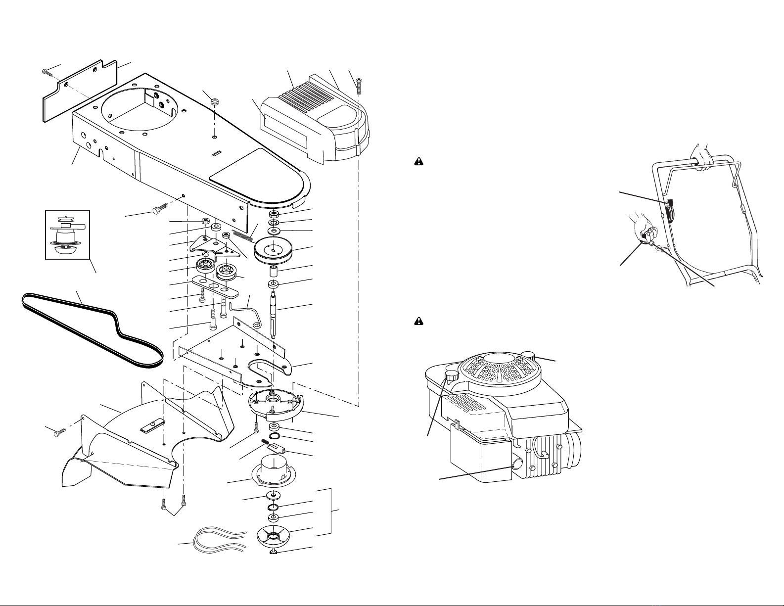
MODEL NUMBER 126M02-0003-F1
BRIGGS & STRATTON 4-CYCLE ENGINE
KEY PART
NO. NO. DESCRIPTION
1 590401 Cylinder Assembly
3 299819s Seal-Oil (Magneto Side)
4 493279 Sump-Engine
5 590411 Head-Cylinder
7 799875 Gasket-Cylinder Head
8 590395 Breather Assembly
9 699472 Gasket-Breather
10 691125 Screw (Breather Assembly)
11 691781 Tube-Breather
11A 691923 Tube-Breather
(Air Cleaner Primer Base)
12 692232 Gasket-Crankcase
13 590422 Screw (Cylinder Head)
(5/16-18 x 2.37)
690912 Screw (Cylinder Head)
(5/16-18 x 2.31)
15 691680 Plug-Oil Drain
16 797018 Crankshaft
20 399781s Seal-Oil (PTO Side)
22 691092 Screw
(Crankcase Cover/Sump)
23 790536 Flywheel
24 222698s Key-Flywheel (Aluminum)
25 590404 Piston Assembly (Standard)
590405 Piston Assembly
(.020" Oversize)
26 590402 Ring Set (Standard)
590403 Ring Set (.020" Oversize)
27 691588 Lock-Piston Pin
28 298909 Pin-Piston
29 797306 Rod-Connecting
32 691664 Screw (Connecting Rod)
(1/4-28 x 1.09)
32A 695759 Screw (Connecting Rod)
(1/4-28 x 1.52)
33 590394 Valve-Exhaust
34 590393 Valve-Intake
35 691270 Spring-Valve (Intake)
36 691270 Spring-Valve (Exhaust)
37 793576 Guard-Flywheel
40 692194 Retainer-Valve
43 691997 Slinger-Governor/Oil
45 690548 Tappet-Valve
46 691449 Camshaft
48 N/A Short Block
50 794305 Manifold-Intake
51 794306 Gasket-Intake
54 691650 Screw (Intake Manifold)
55 697670 Housing-Rewind Starter
58 697316 Rope-Starter
60 281434s Grip-Starter Rope
KEY PART
NO. NO. DESCRIPTION
65 690837 Screw (Rewind Starter)
78 691108 Screw (Flywheel Guard)
81 691740 Lock-Muffler Screw
89 692348 Plug-Oil
97 696565 Shaft-Throttle
104 797622 Pin-Float Hinge
117 799604 Jet-Main (Standard)
121 498260 Kit-Carburetor Overhaul
125 799868 Carburetor
127 694468 Plug-Welch
130 696564 Valve-Throttle
133 398187 Float-Carburetor
134 398188 Kit-Needle/Seat
137 796610 Gasket-Float Bowl
163 795629 Gasket-Air Cleaner
187 791766 Line-Fuel
(Cut to Required Length)
188 693999 Screw (Control Bracket)
190 690940 Screw (Fuel Tank)
202 691829 Link-Mechanical Governor
209 691291 Spring-Governor (Vermillion)
222 790143 Bracket-Control
227 690783 Lever-Governor Control
240 298090s Filter-Fuel
276 271716 Washer-Sealing
287 690940 Screw (Dipstick Tube)
300 692038 Muffler
304 493294 Housing-Blower
305 691108 Screw (Blower Housing)
(1/4-20x.62)
590763 Screw (Blower Housing)
(1/4-20x.78)
306 690450 Shield-Cylinder
307 690345 Screw (Cylinder Shield)
332 690662 Nut (Flywheel)
333 590455 Armature-Magneto
334 691061 Screw (Magneto Armature)
337 591868 Plug-Spark
356 692390 Wire-Stop
358 590508 Gasket Set-Engine
362 793351 Shield-Spark Plug
365 691688 Screw (Carburetor)
404 690272 Washer (Governor Crank)
425 690670 Screw (Air Cleaner Cover)
443 692523 Screw
(Air Cleaner Primer Base)
445 491588s Filter-Air Cleaner Cartridge
455 791960 Cup-Flywheel
456 692299 Plate-Pawl Friction
459 281505s Pawl-Ratchet
505 691251 Nut (Governor Control Lever)