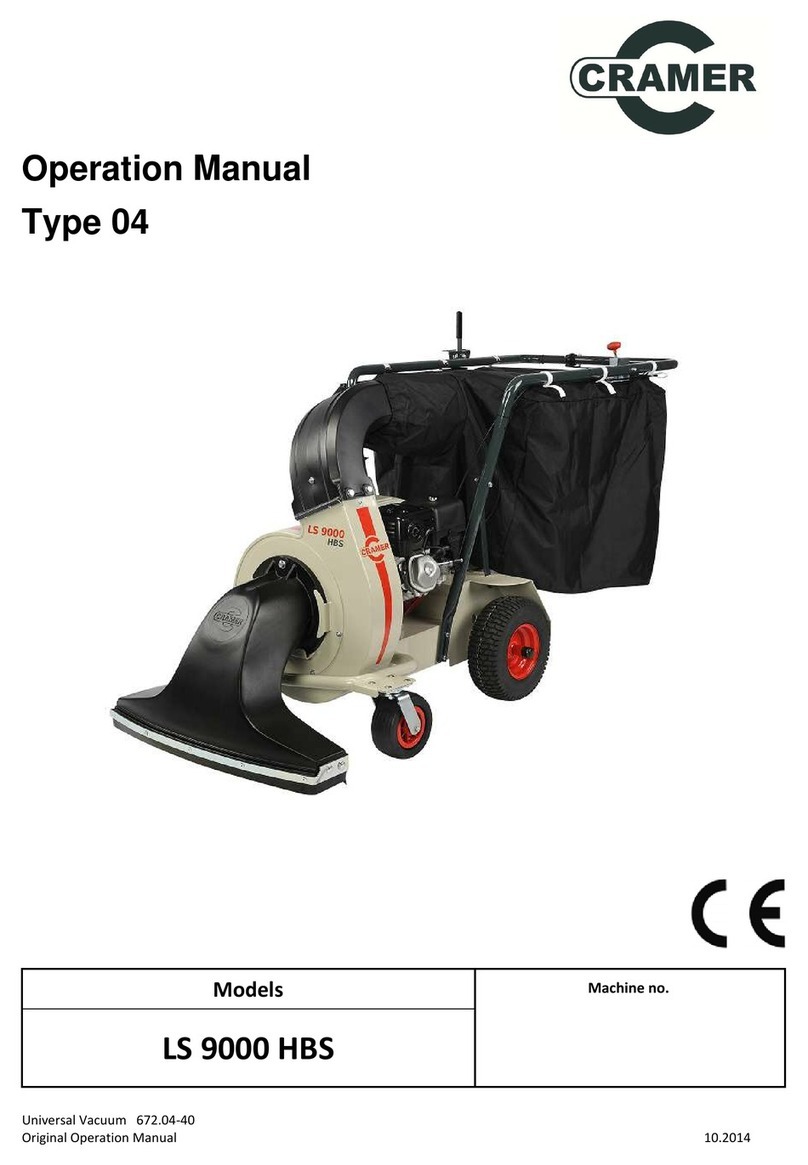
Cramer LS3500 User manual

FOLIAGE- and WASTE-
VACUUM-CLEANER
Operating Instructions
Design: 03
CRAMER-TECHNIK GmbH .Postfach 1269 .D-26762 L r .T l fon 0491-60 95-0 .T l fax 0491-6095-200 · -mail: V rkauf@Cram r-T chnik.d
Contents:
1. Scop of Application
2. D scription
3. Saf ty Instructions
4. Op ration
5. Maint nanc Instructions
6. Spar Parts
7. Troubl shooting
8. T chnical Data
9. Spar Parts Drawing
10. Spar Parts List
Ri 02/18/01
You hav purchas d
th following mod l
(as mark d)
Maschin -Nr.
LS 5000 LS 5000 H
LS 3500
Top-Technique for the Garden

1. Scope of Application
(The digits in text correspond to the ite nu -
bers on spare part list.)
- This machin is approv d for us as a foliag and
gard n wast vacuum (by conv rting th machi-
n into a foliag blow r) as d scrib d in th s
op rating instructions.
- Th machin must not b us d for any oth r pur-
pos . Th manufactur r shall not b liabl for
damag r sulting from improp r us of th quip-
m nt. In such cas s th us r shall b ar sol r s-
ponsibility.
- Prop r us includ s obs rvation of th op rating,
maint nanc and r pair instructions giv n by th
manufactur r.
- Only p rsonn l who ar familiar with th machin
and possibl dang rs should b allow d to op -
rat or r pair th machin .
- Th r l vant accid nt pr v ntion r gulations and
g n rally r cogniz d saf ty rul s shall b obs r-
v d.
- Unauthoriz d chang s to th machin r li v th
manufactur r from any liability for damag s that
might r sult th r from.
2. Description
Th machin com s pr -ass mbl d xc pt for th
foliag bag (8) and th suction nozzl (25/32). Th
suction nozzl and bag should b fitt d as shown in
Fig. 1.
Th vacuum body has 4 wh ls (9/36/46a+b/47);
hard rubb r st ring wh ls at th front (9/47) to
r sist damag by thorns, cushion tyr d wh ls at
th r ar (36/46).
Th driv consists of a 2.6 or 3.75 kW Honda p trol
ngin . Mod l LS 3500 do s not hav a wh l
driv , mod l LS 5000 f atur s a wh l driv . Th
working width is 80 cm. A hand l v r (27) is provi-
d d on th st ring handl to adjust th suction
h ight of th nozzl (3).
Th machin can b conv rt d into a foliag blow r
(s 4. Op ration for furth r d tails).
For furth r t chnical data pl as r f r to th tabl in
S ction 7.
3. Safety Instructions
1. Always ch ck machin for roadworthin ss and
op rating saf ty prior to us .
2. Obs rv all valid saf ty and accid nt pr v nti-
on r gulations in addition to th s op rating
instructions.
3. R ad and und rstand th s op rating and
maint nanc instructions and mak sur that
you ar familiar with th control l m nts and
th ir prop r us .
4. Do not allow p rsonn l to us th machin until
th y hav r ad th s instructions. Sav
instructions for futur r f r nc and ord ring of
spar parts.
5. Mak yours lf familiar with all f atur s and
control l m nts and with th ir functions prior
to op rating th machin .
6. P rsons b low th ag of 14 should not us th
machin .
7. K p p rsons, sp cially childr n and p ts,
away from th working ar a of th machin .
8. To op rat this machin th manufactur r
r comm nds w aring th following:
- saf ty glass s or oth r suitabl y prot c-
tion;
- sturdy sho s;
- no loos fitting clothing that might g t caught
in th machin .
9. Prot ct th machin against rolling away and
us by unauthoriz d p rsonn l.
10. Prior to starting th machin mak sur that
th r is nough fu l in th tank. N v r r fill fu l
in nclos d buildings wh n th ngin is run-
ning or hot. Wip off all spilt fu l b for starting,
or wait until spilt fu l vapours hav vanish d.
11. Exc pt wh n filling p trol, th p trol cap should
always b firmly fitt d on th tank. Wh n hand-
ling fu l, avoid nak d flam s, smoking and
sparks. Stor fu l in appropriat contain rs
only.
12. Prior to carrying out cl aning, r pairs or ins-
p ctions mak sur that all moving parts hav
Vac asse bly
Please see enclosed ounting
instructions
Fig. 1

compl t ly stopp d. Th ngin ignition l v r
should b s t to »0« position so that th ngin
cannot b start d accid ntally. In addition, th
gas l v r must b in »Stop« position.
13. N v r l av th machin unatt nd d whil th
ngin is running.
14. N v r run th ngin in clos d rooms: Dang r of
intoxication!
15. Do not plac hands or f t und r th suction
nozzl or n ar rotating parts.
16. Th ar a to b vacuum d should b cl ar of sto-
n s, wir s tc. which could b pick d up by th
rotor and flung in any dir ction, causing injury to
th op rator or bystand rs.
17. Do not vacuum mat rials that could clog th
rotor.
18. Always switch off th ngin and wait until th
rotor has stopp d compl t ly b for doing th
following:
1. R moving th foliag bag or cl aring a block-
ag in th inf d chann l, or
2. R moving th suction nozzl or cl aring a
blockag in th suction nozzl
3. R pairs, adjustm nts or r moval of for ign
it ms.
19. Wh n using th foliag vacuum as a foliag blo-
w r, th prot ctiv cov r at th rotor inl t has to
b prop rly fitt d. Th blow r should not b poin-
t d at p rsons.
20. Th foliag bag should b cl an d at r gular
int rvals to guarant prop r filt r p rformanc .
21. N v r mpty th foliag bag wh n th ngin is
running.
22. N v r r plac th suction nozzl or suction tub
whil th ngin is running.
23. Us only manufactur r’s approv d acc ssori s
and original spar parts.
24. Only qualifi d p rsonn l should b allow d to
carry out r pairs and maint nanc .
4. Operation
As m ntion d in s ction 2 th machin is pr -ass m-
bl d in th works with th xc ption of th foliag bag
and suction nozzl .
Fit th suction nozzl (3) and foliag bag (8) as shown
in Fig. 1, paying particular att ntion to th adjustm nt
of th Bowd n cabl (25/32) for th switch bar (31) to
pr v nt slipping of th ngin clutch.
Th ngin is start d by m ans of a r coil start r,
aft r first having s t th ignition l v r to »1« and th
gas l v r to »start«. For furth r information, pl as
r f r to th attach d instructions of Honda.
Th suction pow r of th rotor (51) is larg ly d p n-
d nt upon th h ight of th suction nozzl , (3) i. . th
h avi r th mat rial to b pick d up, th low r it
should b (right down for moist foliag and high r for
dry foliag ).
Th front and sid s of th foliag bag (8) ar fitt d
with air-p rm abl filt r mat rial. Th upp r and r ar
surfac is l ss p rm abl out of consid ration for th
op rator. Wh n larg volum s of air ar suck d in, i. .
with a high position of th suction nozzl , additional fil-
t r surfac s can b cr at d by op ning th zips on
th right and l ft.
Th foliag bag is full wh n th machin t nds to tip
backwards, lifting th suction nozzl (3) at th front. In
this cas th foliag bag (8) should b mpti d by
op ning th circumf r ntial zip on th back and mp-
tying it by m ans of th handl provid d on th front
sid . Th op n d part of th bag can b fold d up out
of th way by m ans of a V lcro fast n r.
Mod l LS 3500 has to b push d ov r th surfac s to
b cl an d. Mod l LS 5000/LS 5000 H has a s lf-pro-
p ll d driv which is start d by m ans of th switch
bar (31) on th st ring handl . Mod l LS 5000/LS
5000 H f atur s fr -wh ling ball b arings for curv
n gotiating ability (38).
How to conv rt th foliag vaccum (3) into a foliag
blow r: Unscr w th suction nozzl and th outl t
conn cting pi c (7). To cov r th two op nings, fit
th guard (59) suppli d as an acc ssory. Th n pull
back th locking plat (24) at th back to r l as th
lock and turn th rotor body (51) by approx. 90 d g.
(in count r-clockwis dir ction s n from th front of
th machin ).
Caution: rotation in the wrong direction ight
da age cable to contact switch (5).
5. Maintenance Instructions
Strong vibrations arise when vac is on. It is there-
fore necessary to check screw tightness after a
few working hours.
Always s t th ignition l v r of th ngin to »0« prior
to carrying out maint nanc or r pairs. To cl an th
foliag bag (8), r l as th bag from th outl t (7)
conn cting pi c and undo th r taining straps. Th
filt r mat rial of th foliag bag will v ntually b com
clogg d. In this cas , turn th bag insid out and
shak it out compl t ly, or wash foliag bag in a wat r
bath or by rinsing with wat r; industrial cl aning is
also possibl .
From tim to tim th suction nozzl (3) at th front of
th machin should b dismantl d and th blow r
rotor (14) insp ct d for damag caus d by for ign
it ms.
Ch ck th air pr ssur of th r ar wh ls (36/46a+b)
occasionally according to th t chnical data.
Th driv ngin should b s rvic d as d scrib d in

th attach d instructions of Honda.
All b aring points of th foliag vacuum hav s lf-
lubricating ball b arings and do not hav to b lubri-
cat d.
Mod l LS 5000/LS 5000 H: ch ck driv aft r a long r
p riod of working tim (d p nding on th typ of
ground th vac is us d on). Loos n th four scr ws
holding th bottom plat to uncov r th compl t
driving m chanism (45/66). W ar may hav loos -
n d th wh l driving chain (41/74). To adjust
distanc again, loos n shaft b arings (42) and turn
b arings (42) in slot. Tight n scr ws car fully.
The air filter of the drive engine should be clea-
ned or washed out frequently because handling
foliage always involves a lot of dust.
6. Spare parts
A spar parts drawing and spar parts list is atta-
ch d. Pl as id ntify th r quir d spar parts
according to th drawing and stat th articl num-
b rs giv n in th spar parts list on all ord rs.
7. Troubleshooting
8. Technical Data
Model 3500 Model 5000 Model 5000 H
Drive: P trol ngin typ Honda P trol ngin typ Honda P trol ngin typ Honda
3.5 HP/2.6 kW 5 HP/3.75 kW 5 HP/3.75 kW
Consu ption: 1.1 l/h 1.5 l/h 1.5 l/h
Noise level
without load: 66 db(A) 66 db(A) 66 db(A)
full load: 91 db(A) 91 db(A) 91 db(A)
Tyres
front: dia. 180 x 45 dia. 180x 45 dia. 180x 45
rear: dia. 300x 400-4 dia. 300x 400-4 dia. 300x 400-4
Air pressure, rear tyres: 1,8 bar 1,8 bar 1,8 bar
Weight (kg): 67 70 75
Di ensions:
L( ) 157 157 157
W ( ) 70 70 70
H ( ) 105 105 105
Bag capacitiy: 240 240 240
Working width (c ): 80 80 80
Wheel drive: no y s y s
Fault: Cause: Solution:
1. Engin won’t start – Ingnition switch on ngin in – Turn ignition switch to
»0« position »1« position
2. No ngin pow r – Fu l tank mpty – R fill fu l
– Sparking plug d f ctiv – Exchang sparking plug
– Fu l lin block d or – Empty fu l lin and tank
wat r in p trol and r fill n w p trol
– Air filt r soil d – Cl an (rins ) air filt r
3. Engin g ts too hot – Carbur ttor not adjust d – Adjust carburr tor acc. to
corr ctly Honda instructions
– Insuffici nt ngin oil – Top up with ngin oil
4. No suction pow r – Foliag bag too full – Empty foliag bag
– Filt r ar a of foliag bag – Wip filt r ar as
soil d (dry cl an if n c ssary)
– Suction nozzl block d – Cl an suction nozzl
5. Wh l driv slip – G ar clutch is slipping – Short n Bowd n cabl for
switch bar by shifting
clamping pi c

9. Spare Parts Drawing

10. Spare Parts List
LS 3500 LS 5000 LS 5000 H
It m D scription No. of drawing Art.-No. Art.-No. Art.-No.
1 Rubb r strip 670.01-01-006 99.5.7000 99.5.7000 99.5.7000
2 Clamping strip 670.01-01-005 99.5.7001 99.5.7001 99.5.7001
3 Suction nozzl LS 99.5.7002 99.5.7002
4 Star-grip nut M10x25 99.5.7078 99.5.7078 99.5.7078
5 Contact switch 99.5.7004 99.5.7004
6 H xagon bolt DIN 933-M10x25 99.5.7005 99.5.7005 99.5.7005
7 Outl t conn cting pi c 99.5.7006 99.5.7006
8 Foliag bag 99.5.7007 99.5.7007
9 St ring wh l assy (st l-rim) 99.5.7008 99.5.7008
10 Lock nut DIN 985-M12 99.5.7009 99.5.7009 99.5.7009
11 Plastic bushing 670.01-01-002 99.5.7010 99.5.7010 99.5.7010
12 Wash r DIN 125-Ø13 99.5.7011 99.5.7011 99.5.7011
13 H xagon bolt DIN 933-M12x35 99.5.7012 99.5.7012 99.5.7012
14 Rotor (20 mm ø) LS 5000 670.01-11 99.5.7013 99.5.7013
15 F ath r k y DIN 6886-A5x5x63 99.5.7014 99.5.7014 99.5.7014
16 Top pull y SPZ 50x1 99.5.7015 99.5.7015
17 Tap r bushing PN 20-1610 99.5.7016 99.5.7016
18 Bottom pull y SPZ 150x1 99.5.7017 99.5.7017
19 V-b lt XPZ 687 99.5.7018 99.5.7018
20 Flang b aring RA 20 99.5.7019 99.5.7019
21 T nsion spring 99.5.7020
22 F ath r k y A5x5x25 99.5.7048 99.5.7048
23 Tight n r 670.01-09 99.5.7021
23a Tight n r 675.01-09 99.5.7088
24 Locking plat 670.01-25 99.5.7022 99.5.7022 99.5.7022
25 Bowd n cabl (gas l v r) 99.5.7023
26 Adjusting rod 670.01-12 99.5.7024 99.5.7024 99.5.7024
27 Adjusting l v r 670.01-13 99.5.7025 99.5.7025 99.5.7025
28 Handl 30x4 99.5.7026 99.5.7026 99.5.7026
29 Compr ssion spring 590.01-01-009 99.5.7027 99.5.7027 99.5.7027
29a Wash r DIN 125-Ø8.4 99.5.7028 99.5.7028 99.5.7028
29b H xagon bolt DIN 933-M8x35 99.5.7029 99.5.7029 99.5.7029
29c Wash r (plastic) 99.5.7030 99.5.7030
29d Nut DIN 985-M8 99.5.7031 99.5.7031 99.5.7031
30 Gas l v r assy 99.5.7032
31 Switch bar 670.01-14 99.5.7033 99.5.7033
32 Bowd n cabl (driv ) 99.5.7034
32a Adjustm nt-scr w 99.5.7077 99.5.7077
33 Circlip DIN 471-20x1.2 99.5.7035 99.5.7035 99.5.7035
35a Shaft with sprock d wh l 675.01-16 99.5.7090
35b Shaft with sprock d wh l 670.01-16 99.5.7100
36 Cushion-tyr d wh l (plastic-rim) 99.5.7038
39 Wash r DIN 9021-Ø8.4 99.5.7041 99.5.7041
40 H xagon bolt DIN 933-M8x20 99.5.7042 99.5.7042
41 Chain 670.01-01-008 99.5.7043
42 Flang b aring RA 20 99.5.7019 99.5.7019
43 Sprock t wh l 670.01-10-002 99.5.7045 99.5.7045
44 Split tap r pin DIN 1481-4x16 99.5.7046 99.5.7046
45 G arbox 670.01-10-004 99.5.7047
46 Cushion tyr d wh l (st l-rim) 99.5.7060 99.5.7060
46a Cushion tyr d wh l (st l-rim) right with b aring and fr -wh l 99.5.7101 99.5.7101
46b Cushion tyr d wh l (st l-rim) l ft with b aring and fr -wh l 99.5.7102 99.5.7102
47 St ring wh l (plastic-rim) 99.5.7061
48 axl 660.01-06 99.5.7062
49 Rotor ø 18 mm LS 3500 660.01-07 99.5.7075
50 Distanc -bush 660.01-01-002 99.5.7076
51 Housing 670.03-02 99.5.7071 99.5.7071 99.5.7071
52 Frontplat housing 670.02-20 99.5.7067 99.5.7067 99.5.7067
53 Motorplat LS 3500 660.02-02 99.5.7072
54 Motorplat LS 5000 670.02-05 99.5.7073 99.5.7073
55 Scr w for prot ction DIN 603-M8x20 99.5.7070 99.5.7070 99.5.7073
56 Starlock-cap D20 99.5.7079
57 Wash r DIN 125-Ø21 99.5.7080
58 Split tap r pin DIN 1481-6x40 99.5.7081
59 Saf ty-guard 670.02-18 1429 423 1429 423 1429 423
60 Suction tub with acc ssori s 670.01-28 1429 417 1429 417 1429 417
66 G arbox 675.01-10 99.5.7089
68 Chain prot ction wh l shaft 675.01-15 99.5.7091
69 Bowd n cabl (driv ) 675.01-14 99.5.7092
70 Op rating handl 675.01-06 99.5.7093
72 Shaft for blow r 675.01-12 99.5.7095
73 Pull y guid incl. sprock t 675.01-08 99.5.7096
74 Chain - G arbox 675.01-01-003 99.5.7097
75 Chain for rotor driv 675.01-01-004 99.5.7098
76 R gulating d vic (op rating handl ) 675.01-13 99.5.7099
77 Sprock t - G arbox H (pos. 66) 675.01-10-003 99.5.7104
This manual suits for next models
2
Table of contents
Other Cramer Vacuum Cleaner manuals
