CRATE AUDIO PA6FX User manual
User’s Guide
for the
CRATE AUDIO
PA6FX / PA8FX
Box Mixer with Digital Effects
High
+15dB15dB
Mid
+15dB15dB
Low
+15dB15dB
123456
123456
Level
100
Mon
100
DSP/
Eff
100
DSP/
Eff
100
DSP/
Eff
100
DSP/
Eff
100
DSP/
Eff
100
DSP/
Eff
100
High
+15dB15dB
Mid
+15dB15dB
Low
+15dB15dB
Level
100
Mon
100
High
+15dB15dB
Mid
+15dB15dB
Low
+15dB15dB
Level
100
Mon
100
High
+15dB15dB
Mid
+15dB15dB
Low
+15dB15dB
Level
100
Mon
100
High
+15dB15dB
Mid
+15dB15dB
Low
+15dB15dB
Level
100
Mon
100
High
+15dB15dB
Mid
+15dB15dB
Low
+15dB15dB
Level
100
Mon
100
High
+15dB15dB
Mid
+15dB15dB
Low
+15dB15dB
Main
100
Monitor
100
Tape In
Level
100
DSP
Multi
SAR
LAR
SPR
Delay
Aux/Eff
Ret
100
DSP Ret
100
Effects
Return
Monitor
Out
Effects
Send
Aux In
Tape
In
Tape
Out
MicMicMicMicMic
Mic
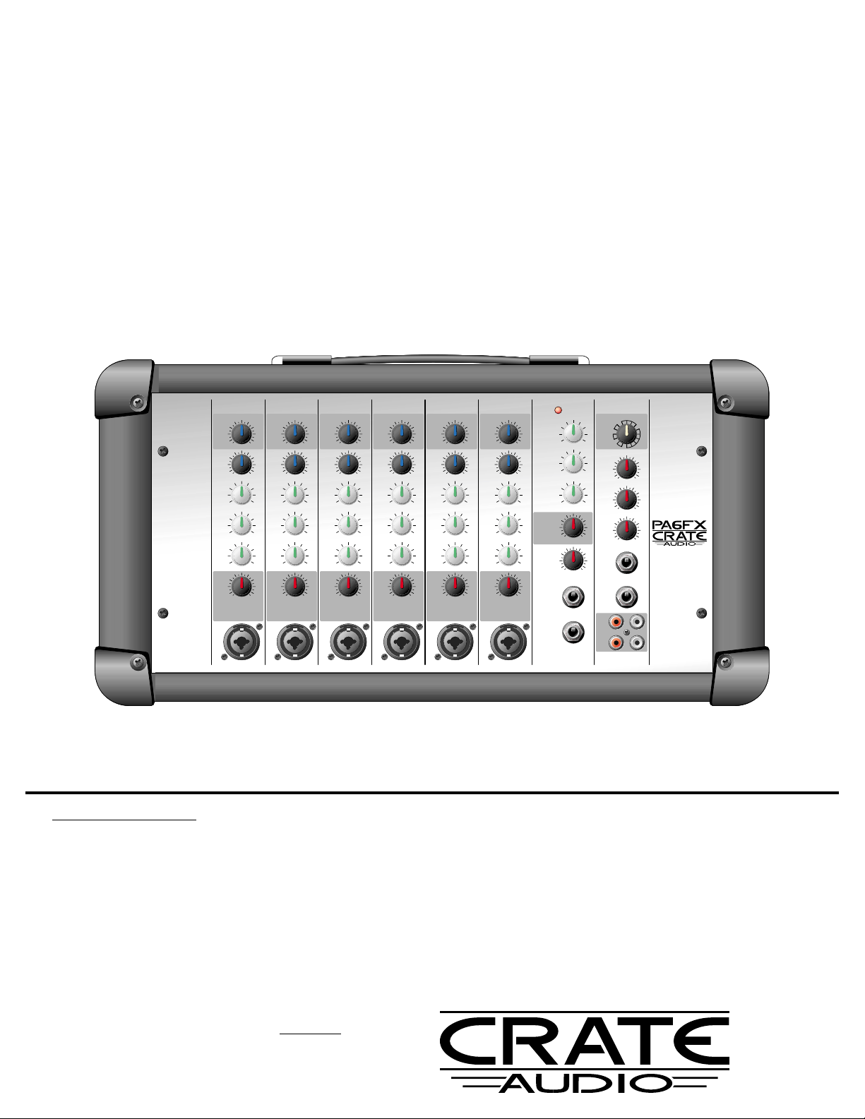
Congratulations!
You are now the proud owner of one of the most versatile and economical powered mixers available, the Crate Audio
PA6FX/PA8FX Box Mixer with Digital Effects. These compact units feature Crate’s legendary performance and high quality con-
struction in rugged and easy to operate packages. Each mixer features a combination 1/4” and XLR-type balanced input jack
on every channel. The Master control section features a three-band EQ, DSP Return, Main Level control, an Effects Loop with
Return Level control, Aux In, Monitor Out with Level control, Tape In/Out jacks and a rotary DSP Effects Selector. The internal
power amplifier is capable of delivering 150 watts into 4 ohms and 220 watts into 2 ohms. Rear-panel Line In/Line Out jacks
and dual 1/4” speaker outputs give you even greater flexibility and performance from these small but power-packed units!
Your PA6FX/PA8FX is designed by musicians and built using only the best components. Extensive testing and Crate’s Five-
Year Warranty assure you that your new mixer is the absolute best it can be. In order to get the most out of it, we strongly
urge you to read this guide before using the mixer.
And thank you for choosing

2
Table of Contents:
The Front Panel . . . . . . . . . . . . . . . . . . . . . . . . . . . . .3,4
The Digital Effects . . . . . . . . . . . . . . . . . . . . . . . . . . . . .4
The Rear Panel . . . . . . . . . . . . . . . . . . . . . . . . . . . . . . .5
Basic Connections and Settings . . . . . . . . . . . . . . . . . . .6
System Block Diagram . . . . . . . . . . . . . . . . . . . . . . . . .7
Technical Specifications . . . . . . . . . . . . . . . . .back cover
PA6FX/PA8FX Box Mixer with Digital Effects
IMPORTANT SAFETY INSTRUCTIONS
•READ, FOLLOW, HEED, AND KEEP ALL INSTRUCTIONS AND WARNINGS.
•DO NOT OPERATE NEAR ANY HEAT SOURCE AND DO NOT BLOCK ANY VENTILATION OPENINGS ON THIS APPARATUS. FOR PROPER OPERATION, THIS UNIT REQUIRES 3”
(75CM) OF WELL VENTILATED SPACE AROUND HEATSINKS AND OTHER AIR FLOW PROVISIONS IN THE CABINET.
•DO NOT USE THIS APPARATUS NEAR SPLASHING, FALLING, SPRAYING, OR STANDING LIQUIDS.
•CLEAN ONLY WITH LINT-FREE DAMP CLOTH AND DO NOT USE CLEANING AGENTS.
•ONLY CONNECT POWER CORD TOA POLARIZED, SAFETY GROUNDED OUTLET WIRED TO CURRENT ELECTRICAL CODES AND COMPATIBLE WITH VOLTAGE, POWER,AND
FREQUENCY REQUIREMENTS STATED ON THE REAR PANEL OF THE APPARATUS.
•PROTECT THE POWER CORD FROM DAMAGE DUE TO BEING WALKED ON, PINCHED, OR STRAINED.
•UNPLUG THE APPARATUS DURING LIGHTNING STORMS OR WHEN UNUSED FOR LONG PERIODS OF TIME.
•ONLY USE ATTACHMENTS, ACCESSORIES, STANDS, OR BRACKETS SPECIFIED BY THE MANUFACTURER FOR SAFE OPERATION AND TOAVOID INJURY.
•THIS APPARATUS DOES NOT OPERATE NORMALLY AND REQUIRES SERVICE WITH ANY PHYSICAL DAMAGE FROM IMPACT OR ANY EXPOSURE TO MOISTURE.
•SERVICE MUST BE PERFORMED BY QUALIFIED PERSONNEL.
•OUR AMPLIFIERS ARE CAPABLE OF PRODUCING HIGH SOUND PRESSURE LEVELS. CONTINUED EXPOSURE TO HIGH SOUND PRESSURE LEVELS CAN CAUSE PERMA-
NENT HEARING IMPAIRMENT OR LOSS. USER CAUTION IS ADVISED AND EAR PROTECTION IS RECOMMENDED IF UNIT IS OPERATED AT HIGH VOLUME.
CAUTION
RISK OF ELECTRIC SHOCK
DO NOT OPEN
WARNING: TO REDUCE THE RISK OF FIRE OR ELECTRIC SHOCK, DO NOT EXPOSE
THIS APPARATUS TO RAIN OR MOISTURE. TO REDUCE THE RISK OF ELECTRIC
SHOCK, DO NOT REMOVE COVER. NO USER-SERVICEABLE PARTS INSIDE. REFER
SERVICING TO QUALIFIED SERVICE PERSONNEL.
PRECAUCION
RIESGO DE CORRIENTAZO
NO ABRA
PRECAUCION: PARA REDUCIR EL RIESGO DE INCENDIOS O DESCARGAS ELECTRICAS, NO PER-
MITA QUE ESTE APARATO QUEDE EXPUESTO A LA LLUVIA O LA HUMEDAD. PARA DISMINUOIR EL
RIESGO DE CORRIENTAZO. NO ABRA LA CUBIERTA. NO HAY PIEZAS ADENTRO QUE EL USARIO
PUEDO REPARAR DEJE TODO MANTENIMIENTO A LOS TECHNICOS CALIFICADOS.
ATTENTION
RISQUE D'ELECTROCUTION
NE PAS OUVRIR
ATTENTION: PROTÉGEZ CET APPAREIL DE LA PLUIE ET DE L'HUMIDITÉ AFIN D'ÉVITER TOUT
RISQUE D'INCENDIE OU D'ÉLECTROCUTION. POUR REDUIRE D'ELECTROCUTION NE PAS ENLEVER
LE COUVERCLE. AUCUNE PIECE INTERNE N'EST REPRABLE PAR L'UTILISATEUR. POUR TOUTE
REPARATION, S'ADRESSER A UN TECHNICIEN QUALIFIE.
"IT IS NECESSARY FOR THE USER TO REFER TO THE INSTRUCTION MANUAL"
“ES NECESARIO QUE EL USUARIO SE REFIERA AL MANUAL DE INSTRUCCIONES.”
"REFERREZ-VOUS AU MANUAL D'UTILISATION"
EXPLANATION OF GRAPHICAL SYMBOLS:
EXPLICACION DE SIMBOLOS GRAFICOS:
EXPLICATION DES SYMBÔLES GRAPHIQUES:
"DANGEROUS VOLTAGE"
“VOLTAJE PELIGROSO”
"DANGER HAUTE TENSION"
==
3
High
+15dB15dB
Mid
+15dB15dB
Low
+15dB15dB
123456
123456
Level
100
Mon
100
DSP/
Eff
100
DSP/
Eff
100
DSP/
Eff
100
DSP/
Eff
100
DSP/
Eff
100
DSP/
Eff
100
High
+15dB15dB
Mid
+15dB15dB
Low
+15dB15dB
Level
100
Mon
100
High
+15dB15dB
Mid
+15dB15dB
Low
+15dB15dB
Level
100
Mon
100
High
+15dB15dB
Mid
+15dB15dB
Low
+15dB15dB
Level
100
Mon
100
High
+15dB15dB
Mid
+15dB15dB
Low
+15dB15dB
Level
100
Mon
100
High
+15dB15dB
Mid
+15dB15dB
Low
+15dB15dB
Level
100
Mon
100
High
+15dB15dB
Mid
+15dB15dB
Low
+15dB15dB
Main
100
Monitor
100
Tape In
Level
100
DSP
Multi
SAR
LAR
SPR
Delay
Aux/Eff
Ret
100
DSP Ret
100
Effects
Return
Monitor
Out
Effects
Send
Aux In
Tape
In
Tape
Out
MicMicMicMicMic
Mic
1
2
3
4
5
6
7
8 9 10 11 12 13 14 15
16 17 18 19 20 21 22
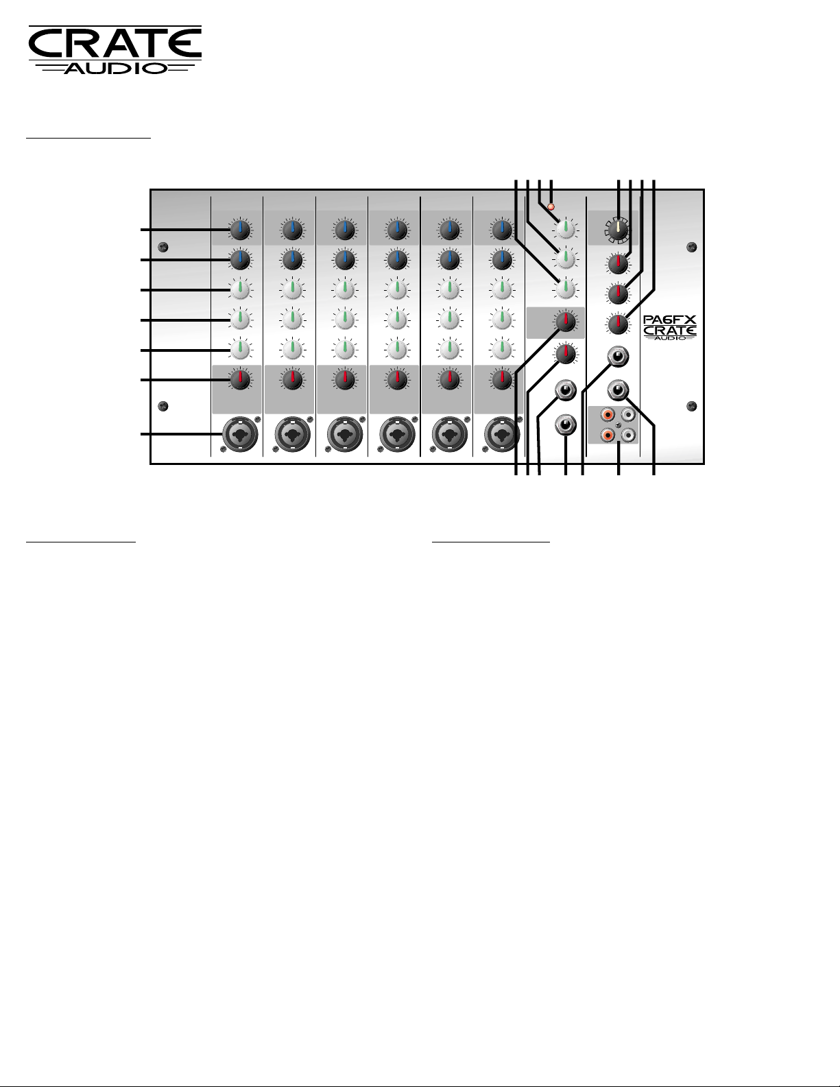
The Front Panel:
EACH CHANNEL:
1: MIC: Use this jack to connect the input signal to the mixer. This combi-
nation jack allows the use of a balanced 1/4” Hi-Z or XLR-type Lo-Z con-
nector. The wiring for this jack is as follows: 1/4” Tip = signal +, Ring = sig-
nal –, Sleeve = signal ground; XLR pin 1 = signal ground, pin 2 = signal +,
pin 3 = signal –.
2: LEVEL: Use this control to adjust the signal level of each channel.
3. LOW EQ: Use this control to adjust each channel’s low frequency output.
The center position is flat - no boost or cut. Rotating the control counter
clockwise reduces the low frequency output; rotating it clockwise increases
the low frequency output. The Low control provides 30dB of boost or cut at
80Hz.
4. MID EQ: Use this control to adjust each channel’s midrange frequency
output. The center position is flat - no boost or cut. Rotating the control
counter clockwise reduces the midrange frequency output; rotating it clock-
wise increases the midrange frequency output. The Mid control provides
30dB of boost or cut at 600Hz.
5. HIGH EQ: Use this control to adjust each channel’s high frequency out-
put. The center position is flat - no boost or cut. Rotating the control count-
er clockwise reduces the high frequency output; rotating it clockwise
increases the high frequency output. The High control provides 30dB of
boost or cut at 10kHz.
6. MON: Use this control to adjust the level of the signal from each channel
to the Monitor bus. This signal is post-level, pre-eq.
7. DSP/EFF: Use this control to adjust the level of the signal sent to the inter-
nal DSP and the Effects Send jack (#19).
MASTER SECTION:
The Master tone controls serve as a three-band EQ to adjust the output of the
mixer to compensate for room acoustics or to fine-tune the overall sound.
The Low control is useful to reduce boominess. The Mid control greatly
enhances the vocals and helps control feedback. The High control helps
compensate for heavily draped, acoustically absorbent rooms, or bare
walled, acoustically reflective rooms, and can be used to help control feed-
back.
8: LOW EQ: Use this control to adjust the mixer’s low frequency output. The
center position is flat - no boost or cut. Rotating the control counter clock-
wise reduces the low frequency output; rotating it clockwise increases the
low frequency output. The Master Low control provides 30dB of boost or cut
at 50Hz and below.
9: MID EQ: Use this control to adjust the mixer’s midrange frequency out-
put. The center position is flat - no boost or cut. Rotating the control count-
er clockwise reduces the midrange frequency output; rotating it clockwise
increases the midrange frequency output. The Master Mid control provides
30dB of boost or cut at 600Hz.
10: HIGH EQ: Use this control to adjust the mixer’s high frequency output.
The center position is flat - no boost or cut. Rotating the control counter
clockwise reduces the high frequency output; rotating it clockwise increases
the high frequency output. The Master High control provides 30dB of boost
or cut at 10kHz and above.
11. POWER LED: This LED illuminates when the mixer is turned on.
12. DSP: Use this control to select one of the sixteen on-board digital effects.
These effects are described in the chart on page 4.
13. DSP RET: Use this control to adjust the level of effected signal coming
from the internal DSP.
14. AUX/EFF RET: Use this control to adjust the level of the signal from the
Aux In jack (#22) and the Effects Return jack (#20).
PA6FX/PA8FX Box Mixer with Digital Effects

4
The Digital Effects
The PA6FX/PA8FX features sixteen built-in digital effects. Rotate the DSP
control (#12) to select the desired effect. Each channel’s DSP/Eff control
(#7) adjusts the amount of effect applied to its channel. The main DSP
Ret control (#13) determines the overall amount of internal effects
applied to the output signal.
The Front Panel - continued:
DSP
Multi
SAR
LAR
SPR
Delay
PA6FX/PA8FX Box Mixer with Digital Effects
The following chart provides a list of the DSP settings along with a brief
description of each effect.
SAR: Small Room 8’ x 8’ empty room w/hardwood floor
Small Rehearsal Hall 20’ x 40’ hall, wood floors, hard walls
LAR: Large Hall 50’ x 100’ hall, about 50 persons
Concert Hall 5000-seat hall, full crowd
SPR: Plate Reverb Simulates studio steel plate reverb
Spring Reverb Simulates multi-spring reverb tank
Delay: Slapback, short 125ms delay + reverb
Slapback, Med-short 240ms delay + reverb
Slapback, Medium 350ms delay + reverb
Slapback, Long 557ms delay - 630’ travel time
Multi: Short Med. Surface 280ms delay w/21.8% regen + reverb
Medium Hard Surface 335ms delay w/26.5% regen + reverb
Chor-Delay 400ms delay with modulation
Chor-Verb Hall reverb w/modulated pre-delay
Slap-Verb Medium hall w/200ms pre-delay
Instrument Doubler Simulates second track slightly out-of-sync
*1
*2
*3
*1SAR - Small Area Reverbs
*2LAR - Large Area Reverbs
*3SPR - Special Reverbs
15. TAPE IN LEVEL: Use this control to adjust the level of the signal from the
tape In jacks (#21).
16. MAIN: Use this control to adjust the main mixed signal level sent to the
mixer’s internal power amplifier. To avoid overdriving the amplifier, this con-
trol should be set around 6 or 7 to allow sufficient headroom for peaks in the
program material.
17. MONITOR: Use this control to adjust the level of the signal from each
channel’s Mon control (#6) sent to the Monitor Out jack (#18).
18. MONITOR OUT: Use this jack to send the monitor signal to your moni-
tor amp and speakers.
19. EFFECTS SEND: Use this jack to send the signal from the DSP/Eff bus
(from each channel’s DSP/Eff control, #7) to the input of an external effects
device. This signal is post-channel level, post-channel eq, pre-master.
20. EFFECTS RETURN: Use this jack to return the output signal of an external
effects device back into the mixer for processing.
21. TAPE IN/TAPE OUT: Use these jacks to connect a tape recorder to the
mixer. Connect the Tape Out jacks to the recorder’s In/Record jacks. Connect
the Tape In jacks to the recorder’s Out/Play jacks. To avoid feedback, turn
down the Tape In Level control (#15) when recording.
22. AUX IN: Use this jack to connect an auxiliary source (such as a tape play-
er, CD payer, etc.) to the mixer. This jack is a mono input - a stereo signal will
have to be mixed down to a mono signal by means of a summing device. This
input is especially useful for expanding the channel count of your P.A. by
adding an external mixer (see page 6).

23. POWER: Use this heavy duty switch to turn the mixer ON (top of the
switch depressed) and OFF (bottom of the switch depressed). The front-
panel “ON” LED (#11) illuminates when the power is on.
24. POWER CORD: The grounded power cord should only be plugged
into a grounded power outlet that meets all applicable electrical codes
and is compatible with the voltage, power, and frequency requirements
stated on the rear panel. Do not attempt to defeat the safety ground
connection.
25. SPEAKER OUTS: Use these jacks to connect the output of the mixer
to your speaker cabinets. Be sure to use heavy gauge speaker cable –
NOT instrument patch cords – for these connections. These jacks are
wired together in parallel.
The internal amplifier of the PA6FX/PA8FX can deliver its full output
into as low as 2 ohms. The chart below can help you determine the total
impedance load when connecting various combinations of speakers in
parallel. NEVER CONNECT THE MIXER TO ANY COMBINATION OF
SPEAKERS THAT HAVE A TOTAL IMPEDANCE BELOW 2 OHMS!
SPKR IMP. # OF SPKRS TOTAL IMP. SPKR IMP. # OF SPKRS TOTAL IMP.
4 ohms 2 2 ohms 16 ohms 2 8 ohms
8 ohms 2 4 ohms 16 ohms 4 4 ohms
8 ohms 4 2 ohms 16 ohms 8 2 ohms
26. EFFECTS LOOP 2 LINE IN: Connecting an external signal processor,
such as an equalizer or compressor, can be accomplished through the
Line In and Line Out jacks. Connect the OUTPUT of the external device
to the Line In jack using a shielded cable with mono 1/4” plugs. This
returns the line level signal into the mixer’s internal power amplifier.
27. EFFECTS LOOP 2 LINE OUT: This carries a pre-amplified, post-EQ
signal to an external effects device. Connect the Line Out jack to the
INPUT of the device using a shielded cable with mono 1/4” phone
plugs. This sends a line level signal out from the mixer.
The rear panel effects loop is post-Main EQ and post-Main Level, there-
fore its tone and output level are governed by the setting of the Master
EQ and Main level controls.
5
7 43565 15531 9
GFX65
(21) SERIAL# BMCDN20083
Line: 120V Freq: 60 Pwr: 22VA
23 24
25 26 27
The Rear Panel:
PA6FX/PA8FX Box Mixer with Digital Effects

6
*1: There are two basic types of mics: Hi-Z (Z = imped-
ance) and Low-Z. Hi-Z connectors plug into the “Hi-Z
Line” inputs, Low-Z connectors plug into the “Lo-Z
Balanced” inputs. For Hi-Z mics, set the Level control
around “9.” For Lo-Z mics, set the Level control
around “4.”
*2: Most guitars have an “instrument level” signal and work best with the Level control set
at “5” or less.
*3: Most keyboards, drum machines, etc. have a “line level” signal and work best with the
Level control set around “2” or “3.”
*4: The Aux In jack sends its signal into the mixer just prior to its Master Level and Tone
controls.
Basic Connections and Settings:
The illustration below offers some basics for using the box mixer. Actual connections
and settings will vary depending on the application. These are merely guidelines.
High
+15dB15dB
Mid
+15dB15dB
Low
+15dB15dB
123456
123456
Level
100
Mon
100
DSP/
Eff
100
DSP/
Eff
100
DSP/
Eff
100
DSP/
Eff
100
DSP/
Eff
100
DSP/
Eff
100
High
+15dB15dB
Mid
+15dB15dB
Low
+15dB15dB
Level
100
Mon
100
High
+15dB15dB
Mid
+15dB15dB
Low
+15dB15dB
Level
100
Mon
100
High
+15dB15dB
Mid
+15dB15dB
Low
+15dB15dB
Level
100
Mon
100
High
+15dB15dB
Mid
+15dB15dB
Low
+15dB15dB
Level
100
Mon
100
High
+15dB15dB
Mid
+15dB15dB
Low
+15dB15dB
Level
100
Mon
100
High
+15dB15dB
Mid
+15dB15dB
Low
+15dB15dB
Main
100
Monitor
100
Tape In
Level
100
DSP
Multi
SAR
LAR
SPR
Delay
Aux/Eff
Ret
100
DSP Ret
100
Effects
Return
Monitor
Out
Effects
Send
Aux In
Tape
In
Tape
Out
MicMicMicMicMic
Mic
EFFECTS
SPEAKERS
TO SPEAKER
JACKS ON BACK
TO EFFECTS LOOP 2
JACKS ON BACK
IN OUT
REC
MONO
OUT
PLAY
LO-Z
MIC
*1
HI-Z
MIC
*1
GUITAR
*2
BASS*2
KEYBOARD*3
CD OR
TAPE
PLAYER
(OUTPUTS
SUMMED TO
MONO SIGNAL)
TAPE PLAYER/
RECORDER
2ΩMIN. LOAD
(UP TO FOUR
8ΩSPEAKERS)
SEE THE CHART
ON PAGE 5
(PE1510H, PE15H,
PSM15, etc.)
SM1-SP, etc.
CMX62,
CSX8, etc.
EQ
LS1-131, etc.
EQ
LS1-131, etc.
POWER AMP
SPA1400, etc.
MONITORS
UFM15H, etc.
D.I. BOX or AMP
LINE OUT
DRUM MIX*4
Typical Hi-Z (1/4”) mic connector:
Typical Lo-Z (XLR) mic connector:
PA6FX/PA8FX Box Mixer with Digital Effects

7
System Block Diagram:
EFFECTS
RETURN
MAIN
AUX/EFF
RET
POWER
AMP
SPEAKER
LINE OUT LINE IN
AUX IN
BUFFER
DSP
EFFECTS
SEND
MONITOR
OUT
LEVEL DSP
RET
DSP/
EFF
MON
LOW MID HIGH
TYPICAL INPUT CHANNEL
MONITOR
LOWMIDHIGH
TAPE IN
LEVEL
TAPE
IN
TAPE
OUT
PA6FX/PA8FX Box Mixer with Digital Effects

www.crateaudio.com
©2002 SLM Electronics, Inc. • A Division of St. Louis Music, Inc.
1400 Ferguson Avenue • St. Louis, MO 63133
47-608-01 •092602
PA6FX/PA8FX Box Mixer with Digital Effects
Technical Specifications
Due to ongoing product development and improvement, the specifications
contained herein are subject to change without notice.
Output Power Rating 150 watts RMS @ 5% THD, 4 ohm load, 120VAC
220 watts RMS @ 5% THD, 2 ohm load, 120VAC
Channel EQs Low ±15dB @ 80Hz
Mid ±15dB @ 600Hz
High ±15dB @ 10kHz
Master EQs Low ±15dB @ 50Hz
Mid ±15dB @ 600Hz
High ±15dB @ 10kHz
Input Impedance High Z 10k ohm
Low Z 1k ohm
Input Sensitivity High Z 20mV RMS
Low Z 2mV RMS
Aux In/Effects Return .25V RMS
Max. Input Signal High Z 4V RMS (11.25V peak-to-peak)
Low Z 40mV RMS (1.25V peak-to-peak)
Aux In/Effects Return 10V RMS (30V peak-to-peak)
Line Out/Line In Levels 1V RMS
Aux In/Tape Out Levels 1V RMS
Effects Return/Effects Send Levels 1V RMS
Power Requirements 120VAC, 60 Hz, 160VA
100/115VAC, 50/60Hz, 160VA
230VAC, 50/60Hz, 160VA
Size and Weight PA6FX PA8FX
10”H x 18”W x 9.5”D 10”H x 20.25”W x 9.5”D
29 lbs. 34 lbs.
The PA Series Box Mixers are covered with a durable, high quality carpet-like material. Brush clean as needed.
Never spray cleaning agents onto the cabinet. Avoid abrasive cleansers which would damage the finish.
Declaration Of Conformity
#17, Effective 01-01-2001
Manufacturer’s Name: SLM Electronics
Production Facility: 11880 Borman Drive, St. Louis, MO 63146, USA
Production Facility: 700 Hwy 202 W, Yellville, AR 72687, USA
Shipping Facility: 1400 Ferguson Ave., St. Louis, MO 63133, USA
Office Facility: 1400 Ferguson Ave., St. Louis, MO 63133, USA
Product Type: Audio Amplifier
Complies with Standards:
LVD: 92/31/EEC, 93/68/EEC, & 73/23/EWG
Safety: EN60065
EMC: EN55013, EN55020, EN55022, EN61000-3-2,
& EN61000-3-3
Supplementary information provided by:
SLM Electronics - R & D Engineering
1901 Congressional Drive, St Louis, MO 63146, USA
Tel.: 314-569-0141, Fax: 314-569-0175
This manual suits for next models
1
Table of contents


