gm-elektronik.swiss | adm@gm-elektronik.swiss
IMPOSTAZIONI
I
10
4.4 Sensibilità del microfono
Quando la postazione si trova vicino ai diffusori, è possibile che si verifichi il cosiddetto “Effetto Larsen”, caratterizzato
da un fischio emesso dagli altoparlanti. Per ovviare a questo fenomeno, è necessario ridurre la sensibilità del microfono
.
Per impostare la sensibilità del microfono, è necessario premere simultaneamente per più di 3 secondi i tasti
ALERT, ed EVAC. Quando il led RUN/SET termina di lampeggiare restando acceso in maniera fissa, rilasciare i
tasti. Tenendo premuto il tasto EVAC., premere AUX per aumentare la sensibilità del microfono oppure P.T. T. per
diminuirla.
I led relativi lampeggeranno ad indicare che la regolazione è in corso; raggiunti i limiti (minimo o massimo) i led
resteranno accesi fissi. Per uscire dalla modalità impostazione e salvare, premere nuovamente i tasti ALERT ed
EVAC: il led RUN/SET torna a lampeggiare. Nel caso NON si vogliano salvare le modifiche, attendere semplicemente
la scadenza del timeout di circa 10 secondi, al termine del quale verranno ripristinati i valori precedenti.
4.3 P.T.T. Toggle
Per impostare la modalità a ritenuta (
toggle)
del tasto P.T.T., è necessario premere simultaneamente per più di
3 secondi i tasti ALERT, EVAC e RESET/ACK. Quando il led RUN/SET termina di lampeggiare restando acceso
in maniera fissa, rilasciare i tasti.
Premendo il tasto RESET/ACK., i led visualizzano l’attuale impostazione (default
di fabbrica:
toggle OFF
). Per modificare lo stato del pulsante, tenere premuto il tasto RESET/ACK. e premere
il tasto AUX (per attivare la modalità
toggle
) o P.T.T. (per disattivarla). Nella tabella sottostante viene indicata la
corrispondenza LED/modalità attiva.
TOGGLE OFF TOGGLE ON
Per uscire dalla modalità impostazione e salvare, premere nuovamente i tasti ALERT, EVAC e RESET/ACK: il led
RUN/SET torna a lampeggiare. Nel caso NON si vogliano salvare le modifiche, attendere semplicemente la scadenza
del timeout di circa 10 secondi, al termine del quale verranno ripristinati i valori precedenti.
SETTINGS
UK
22
4.6 LOW-CUT filter
To set the LOW-CUT filter, press the ALERT and EVAC keys simultaneously and hold them down for more
than 3 seconds. When the RUN/SET LED stops flashing and remains steady ON, release the keys.
Press the RESET/ACK. key. The LEDs will indicate the current settings:
AUX LED ON = filter ON
P.T.T. LED ON = filter OFF
Holding the RESET/ACK key down, press AUX to activate the filter or P.T.T. to de-activate it.
To leave the settings mode and save the changes made, press the ALERT and EVAC keys again. The RUN/SET
LED will start flashing again. If you do NOT want to save the changes made, simply wait for the timeout (about 10
seconds), after which the previous settings will be restored.
Note: To check the effects of the changes described under points 4.3 to 4.6 above, a normal call so as to
listen to your own voice is recommended.
Note for INSTALLERS:
While installing and configuring the system, it may be necessary to mute the failure signalling buzzer temporarily.
To do this, there is a switch (11) on the rear panel, which has to be positioned with a small screwdriver. Remember
to re-activate the buzzer after completing the operations.
4.5 Output level
To set the output level, press the ALERT and EVAC keys simultaneously and hold them down for more than
3 seconds. When the RUN/SET LED stops flashing and remains steady ON, release the keys. Holding the ALERT
key down, press AUX to increase the output level or P.T.T. to decrease it.
The appropriate LEDs will flash to indicate that the adjustment is being made. Once the (minimum or maximum)
limits have been reached, the LEDs will remain steady ON. To leave the settings mode and save the changes made,
press the ALERT and EVAC keys again. If you do NOT want to save the changes made, simply wait for the timeout
(about 10 seconds), after which the previous settings will be restored.
D at a sh e et 1811. 0 01
DIGITAL MICROPHONE CONSOLE VA-FMC-512
Page 8 | 9
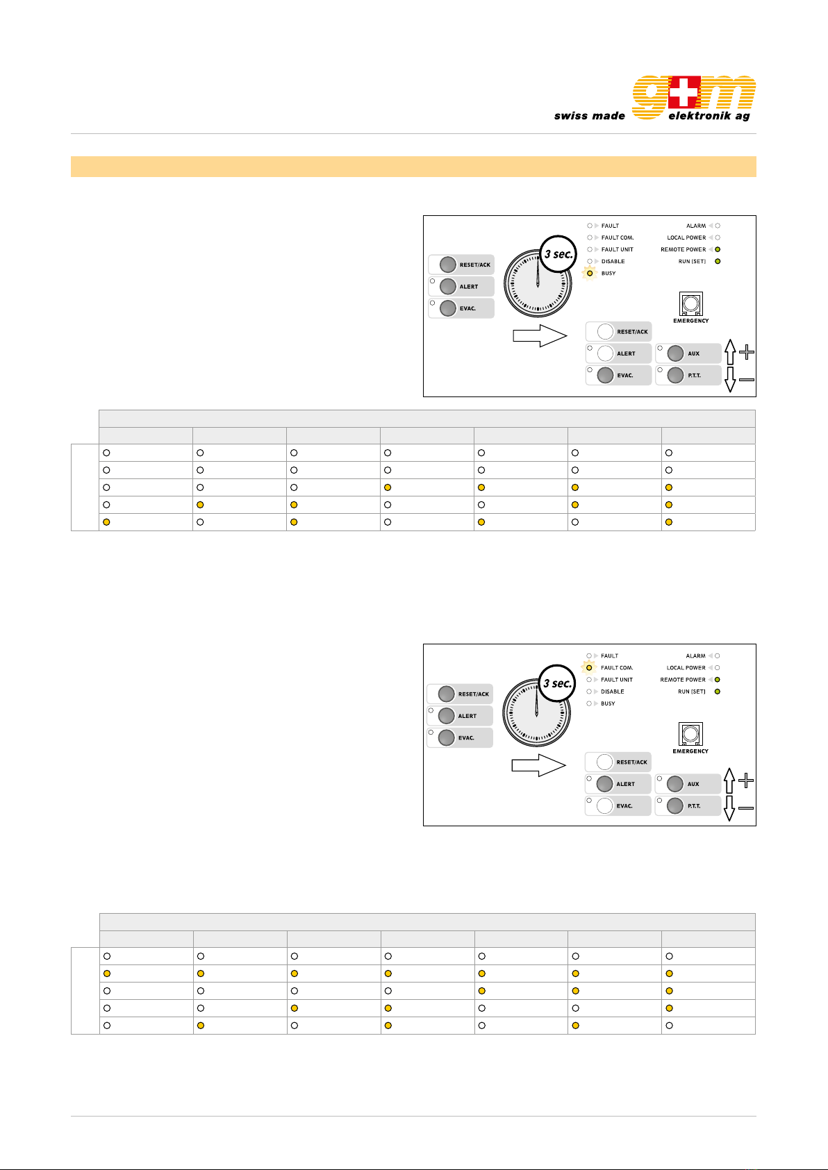
3.3. P.T.T. Toggle
To set the P.T.T. key in the toggle mode, press the ALERT,
EVAC and RESET / ACK keys simultaneously and hold them
down for more than 3 seconds. When the RUN/SET LED
stops flashing and remains steady ON, release the keys. On
pressing the RESET / ACK. key, the LEDs will show the cur-
rent setting (default factory setting: toggle OFF). To change
the status, hold the RESET / ACK. key down and press AUX
(to activate the toggle mode) or the P.T.T. key (to de-activate
it). The LED’s corresponding to the modes are shown in the
following table.
To leave the settings mode and save the changes made,
press the ALERT, EVAC and RESET / ACK keys again: the
RUN / SET LED will start flashing again. If you do NOT want
to save the changes made, simply wait for the timeout
(about 10 seconds), after which the previous settings will be
restored.
Toggle off Toggle on
LED
FAULT FAULT
FAULT COM. FAULT COM.
FAULT UNIT FAULT UNIT
DISABLE DISABLE
BUSY BUSY
3.4. Microphone sensitivity
When the station is close to the speakers, it is possible that
acoustic feedback may occur, resulting in a hissing noise
from the loudspeakers (Larsen effect). To avoid this, it is ne-
cessary to lower the sensitivity of the microphone. To set the
sensitivity of the microphone, press the ALERT and EVAC
keys simultaneously and hold them down for more than 3 se-
conds. When the RUN / SET LED stops flashing and remains
steady ON, release the keys.
Holding the EVAC. key down, press AUX to increase the sen-
sitivity of the microphone or P.T.T. to decrease it.
The appropriate LED’s will flash to indicate that the adjust-
ment is being made.
Once the (minimum or maximum) limits have been reached,
the LED’s will remain steady ON. To leave the settings mode
and save the changes made, press the ALERT and EVAC
keys again. If you do NOT want to save the changes made,
simply wait for the timeout (about 10 seconds), after which
the previous settings will be restored.
3.5. Output level
To set the output level, press the ALERT and EVAC keys si-
multaneously and hold them down for more than 3 seconds.
When the RUN / SET LED stops flashing and remains steady
ON, release the keys. Holding the ALERT key down, press
AUX to increase the output level or P.T.T. to decrease it.
The appropriate LED’s will flash to indicate that the adjust-
ment is being made. Once the (minimum or maximum) limits
have been reached, the LED’s will remain steady ON. To lea-
ve the settings mode and save the changes made, press the
ALERT and EVAC keys again. If you do NOT want to save
the changes made, simply wait for the timeout (about 10 se-
conds), after which the previous settings will be restored.