Cray T3E User manual

HMM-164-0 Cray Research Proprietary 1
CRAY T3E AC System: Single-cabinet Installation
HMM-164-0
Record of Revision . . . . . . . . . . . . . . . . . . . . . . . . . . . . . . . . . . . . . . . . . . . 4
Overview . . . . . . . . . . . . . . . . . . . . . . . . . . . . . . . . . . . . . . . . . . . . . . . . . . . 4
Important Safety Information . . . . . . . . . . . . . . . . . . . . . . . . . . . . . . . . . . . 5
Hazard Statements . . . . . . . . . . . . . . . . . . . . . . . . . . . . . . . . . . . . . . . . . 5
ESD Precautions . . . . . . . . . . . . . . . . . . . . . . . . . . . . . . . . . . . . . . . . . . 5
ESD Smock . . . . . . . . . . . . . . . . . . . . . . . . . . . . . . . . . . . . . . . . . . . 5
Wrist Strap . . . . . . . . . . . . . . . . . . . . . . . . . . . . . . . . . . . . . . . . . . . . 6
Safety Precautions . . . . . . . . . . . . . . . . . . . . . . . . . . . . . . . . . . . . . . . . . 6
Preinstallation Activities . . . . . . . . . . . . . . . . . . . . . . . . . . . . . . . . . . . . . . . 8
Tools Required . . . . . . . . . . . . . . . . . . . . . . . . . . . . . . . . . . . . . . . . . . . . 8
Checking Site Planning Requirements . . . . . . . . . . . . . . . . . . . . . . . . . . 8
Checking the Power Cord Receptacle . . . . . . . . . . . . . . . . . . . . . . . . . . 9
Power Wiring for High-leakage Current . . . . . . . . . . . . . . . . . . . . . . . . 11
Unloading the Computer System Equipment . . . . . . . . . . . . . . . . . . . . . . . 11
Inspecting the System Crates and Boxes . . . . . . . . . . . . . . . . . . . . . . . . . . . 12
Transporting the System to the Designated Location . . . . . . . . . . . . . . . . . 13
Opening the “OPEN FIRST” Box . . . . . . . . . . . . . . . . . . . . . . . . . . . . . . . . 13
Unpacking the CRAY T3E AC Cabinet . . . . . . . . . . . . . . . . . . . . . . . . . . . . 14
Unpacking and Positioning the PC-10 . . . . . . . . . . . . . . . . . . . . . . . . . . . . . 23
Unpacking and Positioning the System Workstation (SWS) . . . . . . . . . . . . 23
Unpacking and Positioning Additional System Components . . . . . . . . . . . 23
Grounding the Mainframe Chassis . . . . . . . . . . . . . . . . . . . . . . . . . . . . . . . 24
Verifying the CRAY T3E AC Hardware . . . . . . . . . . . . . . . . . . . . . . . . . . . 25
Verifying the Voltage Selector Switch . . . . . . . . . . . . . . . . . . . . . . . . . . 26
Connecting the Optional Customer Alarm . . . . . . . . . . . . . . . . . . . . . . 27
Verifying the Control System Hardware . . . . . . . . . . . . . . . . . . . . . . . . 30
Verifying Additional Power Hardware . . . . . . . . . . . . . . . . . . . . . . . . . 32
Verifying that the Modules Are Seated and Cammed . . . . . . . . . . . . . . 33

CRAY T3E AC System: Single-cabinet Installation
2 CrayResearchProprietary HMM-164-0
Completing the Cabling . . . . . . . . . . . . . . . . . . . . . . . . . . . . . . . . . . . . . . . . 35
Cable Labels . . . . . . . . . . . . . . . . . . . . . . . . . . . . . . . . . . . . . . . . . . . . . . 36
Connecting the WACS . . . . . . . . . . . . . . . . . . . . . . . . . . . . . . . . . . . . . . 37
Connecting the GigaRing Cables . . . . . . . . . . . . . . . . . . . . . . . . . . . . . . 38
Verifying System Cabling . . . . . . . . . . . . . . . . . . . . . . . . . . . . . . . . . . . 42
Powering Up the System Workstation (SWS) . . . . . . . . . . . . . . . . . . . . . . . 42
Powering Up the PC-10 . . . . . . . . . . . . . . . . . . . . . . . . . . . . . . . . . . . . . . . . 42
Connecting the Input Power to the CRAY T3E Cabinet . . . . . . . . . . . . . . . 42
Verifying Cabinet Operation . . . . . . . . . . . . . . . . . . . . . . . . . . . . . . . . . . . . 43
Verifying WACS Control . . . . . . . . . . . . . . . . . . . . . . . . . . . . . . . . . . . . 43
Verifying Correct Operation of the Blower . . . . . . . . . . . . . . . . . . . . . . 44
Verifying Correct Operation of the Thermistors . . . . . . . . . . . . . . . . . . 44
Verifying Cabinet Power Switch and Shunt Trip Operation . . . . . . . . . 44
Verifying Remote Alarm Operation (Optional, if Connected) . . . . . . . . 45
Powering up the Modules . . . . . . . . . . . . . . . . . . . . . . . . . . . . . . . . . . . . . . 45
Verifying Remote Power On/Off . . . . . . . . . . . . . . . . . . . . . . . . . . . . . . . . . 46
Preparing the System for Initial Operation . . . . . . . . . . . . . . . . . . . . . . . . . 47
Figures
Figure 1. Power Plugs and Receptacles . . . . . . . . . . . . . . . . . . . . . . . . . 10
Figure 2. CRAY T3E AC Cabinet Shipping Configuration . . . . . . . . . . 12
Figure 3. Cabinet Shipping Crate . . . . . . . . . . . . . . . . . . . . . . . . . . . . . . 15
Figure 4. Retaining Block and Screws . . . . . . . . . . . . . . . . . . . . . . . . . . 16
Figure 5. Installing the Ramp . . . . . . . . . . . . . . . . . . . . . . . . . . . . . . . . . 17
Figure 6. Cardboard Shipping Container . . . . . . . . . . . . . . . . . . . . . . . . 18
Figure 7. Removing the Inside Retaining Bar . . . . . . . . . . . . . . . . . . . . 19
Figure 8. Shipping Bolts . . . . . . . . . . . . . . . . . . . . . . . . . . . . . . . . . . . . . 20
Figure 9. Example Cabinet Floor Plan . . . . . . . . . . . . . . . . . . . . . . . . . . 21
Figure 10. Door Latches and Handle (Front Door) . . . . . . . . . . . . . . . . . . 22
Figure 11. Chassis Ground Connections (Rear View of Cabinet) . . . . . . 24
Figure 12. CRAY T3E Cabinet Components -- Front View . . . . . . . . . . . 25
Figure 13. Voltage Selector Switch (SW1) . . . . . . . . . . . . . . . . . . . . . . . . 26

CRAY T3E AC System: Single-cabinet Installation
HMM-164-0 Cray Research Proprietary 3
Figure 14. Power-cord Cover and Power-box Cover (Removed) . . . . . . . 27
Figure 15. Filter Bracket . . . . . . . . . . . . . . . . . . . . . . . . . . . . . . . . . . . . . . 28
Figure 16. Remote Alarm Contacts - Locations . . . . . . . . . . . . . . . . . . . . 29
Figure 17. WACS Panel . . . . . . . . . . . . . . . . . . . . . . . . . . . . . . . . . . . . . . 30
Figure 18. WACS with Front Panel Open . . . . . . . . . . . . . . . . . . . . . . . . . 31
Figure 19. Power Supply Rack . . . . . . . . . . . . . . . . . . . . . . . . . . . . . . . . . 32
Figure 20. Module Setting Screw Locations (Rear View of Cabinet) . . . 33
Figure 21. Module Camming . . . . . . . . . . . . . . . . . . . . . . . . . . . . . . . . . . 34
Figure 22. Typical System - Block Diagram . . . . . . . . . . . . . . . . . . . . . . . 35
Figure 23. WACS Connector Location on I/O Bulkhead . . . . . . . . . . . . . 37
Figure 24. I/O Bulkhead - Connector Locations . . . . . . . . . . . . . . . . . . . . 38
Figure 25. Example GigaRing Connections . . . . . . . . . . . . . . . . . . . . . . . 39
Figure 26. GigaRing Connectors on PC-10 (Rear View) . . . . . . . . . . . . . 40
Figure 27. NSR-1 GigaRing Connectors . . . . . . . . . . . . . . . . . . . . . . . . . 41
Figure 28. MPN-1 GigaRing Connectors . . . . . . . . . . . . . . . . . . . . . . . . . 41
Figure 29. WACS Summary Screen - Standby Mode . . . . . . . . . . . . . . . . 43
Figure 30. Power Supply Circuit Breakers and LEDs . . . . . . . . . . . . . . . 45
Figure 31. T3EMS Main Window . . . . . . . . . . . . . . . . . . . . . . . . . . . . . . 48
Figure 32. T3EMS Scan Tool Options Window . . . . . . . . . . . . . . . . . . . . 49
Figure 33. Load Program Window . . . . . . . . . . . . . . . . . . . . . . . . . . . . . . 50
Figure 34. PE Configuration Window . . . . . . . . . . . . . . . . . . . . . . . . . . . . 51
Tables
Table 1. Required Power Receptacle Test Readings . . . . . . . . . . . . . . . 10
Table 2. Remote Alarm Contacts - Descriptions . . . . . . . . . . . . . . . . . . 29
Table 3. Bottom Scanner DIP Switch Functions . . . . . . . . . . . . . . . . . . 31
Table 4. Cable Labels . . . . . . . . . . . . . . . . . . . . . . . . . . . . . . . . . . . . . . 36
Table 5. Example Cable Label . . . . . . . . . . . . . . . . . . . . . . . . . . . . . . . 36
Table 6. CRAY T3E AC I/O Bulkhead GigaRing Connections . . . . . . 38
Table 7. Offline Diagnostic Tests . . . . . . . . . . . . . . . . . . . . . . . . . . . . . 53

Record of Revision CRAY T3E AC System: Single-cabinet Installation
4 CrayResearchProprietary HMM-164-0
Record of Revision
Revision 0: October 1996
Original printing.
Overview
These installation procedures are intended to assist Cray Research personnel
with the mechanical installation of a single CRAY T3E air-cooled (AC) cabinet.
Inaddition,theproceduresprovideanoverviewofthesysteminstallation,which
includes the installation of the peripheral cabinet (PC-10) and the system
workstation (SWS). The installation includes the following tasks:
•Unpacking and positioning the system components
•Verifying the hardware and connecting the cables
•Powering on the system initially and verifying cabinet operation
•Verifying system functionality with validation diagnostics
Perform the procedures in the order that they are presented.
This document does not contain troubleshooting procedures, nor does it contain
installation procedures for peripheral equipment.
For information on the PC-10 installation, refer to Peripheral Cabinet (PC-10)
Installation, publication HMM-371. For information on the SWS installation,
refer to System Workstation, publication HTM-222.
For information on the CRAY T3E software installation, refer to the CRAY T3E
Software Installation and Configuration Guide, publication SG-2610.
Installationpersonnel shouldhaveabasic knowledgeofcomputer systempower
processes. They should also have a basic understanding of the control system,
the layout of the various cabinet components, and of running offline diagnostics.
The installation coordinator is responsible for CRUISE (Cray Research Unified
System Enterprise) registration and for installation reporting. The system log
book in the “OPEN FIRST” box contains a printout from the Web-based
Installation Reporting tool. You may use the paper copy to help track the
installation and, if necessary, to fax the information.

CRAY T3E AC System: Single-cabinet Installation Important Safety Information
HMM-164-0 Cray Research Proprietary 5
Important Safety Information
The following subsections contain important safety information that you must
read and understand before you begin the CRAY T3E AC system installation.
Hazard Statements
During the installation of the computer system, be alert for hazard advisory
statements. The following list describes the hazard statement signal words:
•Danger indicates an imminently hazardous situation that, if not avoided,
will result in death or serious injury.
•Warning indicates a potentially hazardous situation that, if not avoided,
could result in death or serious injury.
•Caution indicates a potentially hazardous situation that, if not avoided,
may result in minor or moderate injury. This signal word is also used to
alert personnel against unsafe practices that can result in equipment
damage and/or data corruption.
ESD Precautions
Observe electrostatic discharge (ESD) precautions during the entire installation
process. Required apparel includes an ESD smock and an ESD wrist strap.
ESD Smock
Wear a Cray Research-approved static-dissipative smock when servicing or
handling an ESD-sensitive device. Completely button the smock and wear it as
the outermost layer of clothing. You must have a portion of the smock’s sleeves
in direct contact with the skin of your arms. Skin contact is essential for a
dissipativepath-to-earth groundthroughyour wriststrap.Tuckhairthat exceeds
shoulder length inside the back of the smock.
CAUTION
Observe all ESD precautions. Failure to
do so could result in damage to the
equipment.

Important Safety Information CRAY T3E AC System: Single-cabinet Installation
6 CrayResearchProprietary HMM-164-0
Wrist Strap
Wear a Cray Research-approved wrist strap when servicing or handling an
ESD-sensitive device to eliminate possible ESD damage to equipment. Connect
the wrist strap cord directly to earth ground.
NOTE: The CRAY T3E AC cabinet contains two sets of jacks (front and
rear) for a mating ESD ground strap.
Safety Precautions
Beforeyouperformtheproceduresinthisdocument,takeafewminutestoreview
the Safety and ESD Guidelines, publication number HGM-016-A. In addition,
observethefollowingsafetymeasureswheninstalling,repairing,ormaintaining
the system.
•Use caution when removing the cabinets from the ramps. Moving these
cabinets can cause personal injury or property damage if the cabinets are
not handled properly.
•Ensure that the cabinet crates are positioned close to their final positions
before you unpack them.
•Do not move the cabinets while they are connected to power.
•Do not wear watches or jewelry when you work on a CRAY T3E system
cabinet.
•Keep fingers and conductive tools away from high-voltage areasand from
high-current areas.
•Ensure that a qualified electrician has properly installed the power
receptacles.
DANGER
Keep fingers and conductive tools away
from high-voltage areas. Serious injury
or death will occur if these precautions
are not followed.
CRAY T3E AC System: Single-cabinet Installation Important Safety Information
HMM-164-0 Cray Research Proprietary 7
•Set all circuit breakers to the OFF (0) position before you plug in the
system power cord.
•Unplug, lock, and tag the cabinet power plug before you work on the
power system components.
•Remove all tools from the system cabinets after you service them.
•Replace all covers and panels that you removed from the system during
servicing.
•Power off the system only after the system software has been shut down
in an orderly manner.
DANGER
Unplug, lock, and tag the AC cord.
Failure to do so will result in damage to
the equipment and serious injury or
death to the maintenance person.
CAUTION
If you power off the system before you halt the
operating system, you may lose customer data.

Preinstallation Activities CRAY T3E AC System: Single-cabinet Installation
8 CrayResearchProprietary HMM-164-0
Preinstallation Activities
Before you install your system, read the following subsections and verify that
your site meets all site requirements. In addition, reread the “Important Safety
Information” section of this document as part of your preinstallation activities.
Tools Required
Ensure that you have the following tools, which are necessary to complete the
hardware installation. These tools are available from Cray Research’s Customer
Service Logistics department or from any hand-tool vendor. (The Logistics part
number for the CRAY T3E tool kit is 57247800.)
•Multimeter
•Cutters
•Adjustable wrench or 11-mm, 15-mm, and 16-mm wrenches
•3-mm and 4-mm hex (allen) wrenches with hex driver
•#1 and #2 Phillips screwdrivers
•Small and medium flatblade screwdrivers
•Flashlight
•Heat gun (optional -- to verify operation of remote alarm, if used)
Checking Site Planning Requirements
Before you install your CRAY T3E system, ensure that your site meets all of the
site planning requirements included in Preparing for a CRAY T3E Air-cooled
SystemInstallation,CrayResearchpublicationnumberHR-04118.Forexample,
take some time to verify the following things:
•Verify that the site has appropriate means (pallet jacks, etc.) for unloading
and transporting the system components.
•Verify that the route to the computer room is free of obstacles.
•Verify that the computer room floor is prepared according to the floor
layout diagram for the system.
•Verify that all electrical services meet site planning specifications.
•Verify that the air-conditioning equipment meets site planning
specifications.
•Verify that the ground clamp (for grounding the mainframe to the floor
grid) is in the correct location near the floor cutout for I/O cables.
CRAY T3E AC System: Single-cabinet Installation Preinstallation Activities
HMM-164-0 Cray Research Proprietary 9
Checking the Power Cord Receptacle
Ensure that a qualified technician installed the correct power receptacle
accordingto siteplanningspecifications. ThenCray Research-trainedpersonnel
with the appropriate skills should use the following procedure to ensure that the
powerreceptacleisproperlywired.RefertoFigure 1fordrawingsofthe3-phase
power plugs and receptacles that are available for CRAY T3E AC cabinets.
1. Turn off, lock, and tag the customer’s circuit breaker(s) that control power
for the CRAY T3E AC cabinet power receptacle before you perform
Step 2 and Step 3.
2. Set the multimeter to a low-resistance setting.
3. Measure between the power receptacle ground-post hole and an
appropriate earth-ground location and ensure that resistance is less than
1 ohm. Figure 1 shows the post hole locations. (Appropriate earth-ground
locations could include the floor grid, a metal case receptacle, and a
circuit breaker shell.)
4. Remove the lock and tag and restore power through the customer’s circuit
breaker(s).
5. Set the multimeter to a high AC voltage range.
6. Measure between the ground-post hole and an appropriate earth-ground
location. If you detect voltage on the ground-post hole, contact a
site-approved electrician. Do not proceed with the installation.
NOTE: The ground wire may act as an antenna and, through
impedance, generate a low voltage (usually less than 1 Vac).
This is normal.
7. Perform voltage checks between the posts listed in Table 1. Refer again to
Figure 1, which shows the post locations. (Table 1 is based on a
wye-connected power source.)
DANGER
Ensure that the electrical circuit
breakers for the power receptacle being
checked are off, locked, and tagged.
Failure to do so could result in severe
shock and burns.

Preinstallation Activities CRAY T3E AC System: Single-cabinet Installation
10 CrayResearchProprietary HMM-164-0
Table 1. Required Power Receptacle Test Readings
Figure 1. Power Plugs and Receptacles
Cord Assembly From Post To Post Meter Reading
P/N 57181600
60 A, 250 Vac
(4-post cord
used commonly
inNorthAmerica
and Japan)
L1 G Not to exceed 140 Vac
L2 G Not to exceed 140 Vac
L3 G Not to exceed 140 Vac
L1 L2 Between 180 and 240 Vac
L2 L3 Between 180 and 240 Vac
L1 L3 Between 180 and 240 Vac
P/N 57181700
32 A, 400 Vac
(5-post cord
used commonly
in Europe)
L1 N Not to exceed 260 Vac
L2 N Not to exceed 260 Vac
L3 N Not to exceed 260 Vac
L1 L2 Between 360 and 440 Vac
L2 L3 Between 360 and 440 Vac
L1 L3 Between 360 and 440 Vac
L1
L2 L3
N
L2
L3
4-post (~250 Vac) Power
Plug and Receptacles
L1
Ground
L3
L2 L2
Ground
Ground
L1
N
L3
N
L1
Ground
5-post (400 Vac) Power
Plug and Receptacles
L2
CRAY T3E AC System: Single-cabinet Installation Unloading the Computer System Equipment
HMM-164-0 Cray Research Proprietary 11
Power Wiring for High-leakage Current
Please note the following statement by Underwriters Laboratories, Inc.
An insulated earthing conductor that is identical in size, insulation material, and
thickness to the earthed and unearthed branch-circuit supply conductors except
that it is green with or without one or more yellow stripes is to be installed as
partof thebranch circuitthat suppliestheunitorsystem. Theearthing conductor
described is to be connected to earth at the service equipment or, if supplied by
a separately derived system, at the supply transformer or motor-generator
(UL 60 95).
Unloading the Computer System Equipment
In most cases, if your loading dock is the same height as the transportation
vehicle, you may use pallet jacks to unload the system from the transportation
vehicle. Follow any instructions that are printed on the packing crates.
If the loading dock is not the same height as the vehicle, you must provide a
forklift or another approved method to unload the system. A platform or ramp
may be used to obtain the desired level as long as the ramp does not exceed a
ratio of 1 unit vertical to 6 units horizontal. Refer to Preparing for a CRAY T3E
Air-cooled System Installation, publication HR-04118, for more information on
site requirements.
Ifthecomputersitedoesnothavealoadingdock,arrange foraforklifttoremove
the computer from the transportation vehicle.
Ensure that three or four personnel are available to help move the mainframe
chassis. Perform all movement of the chassis slowly and carefully.
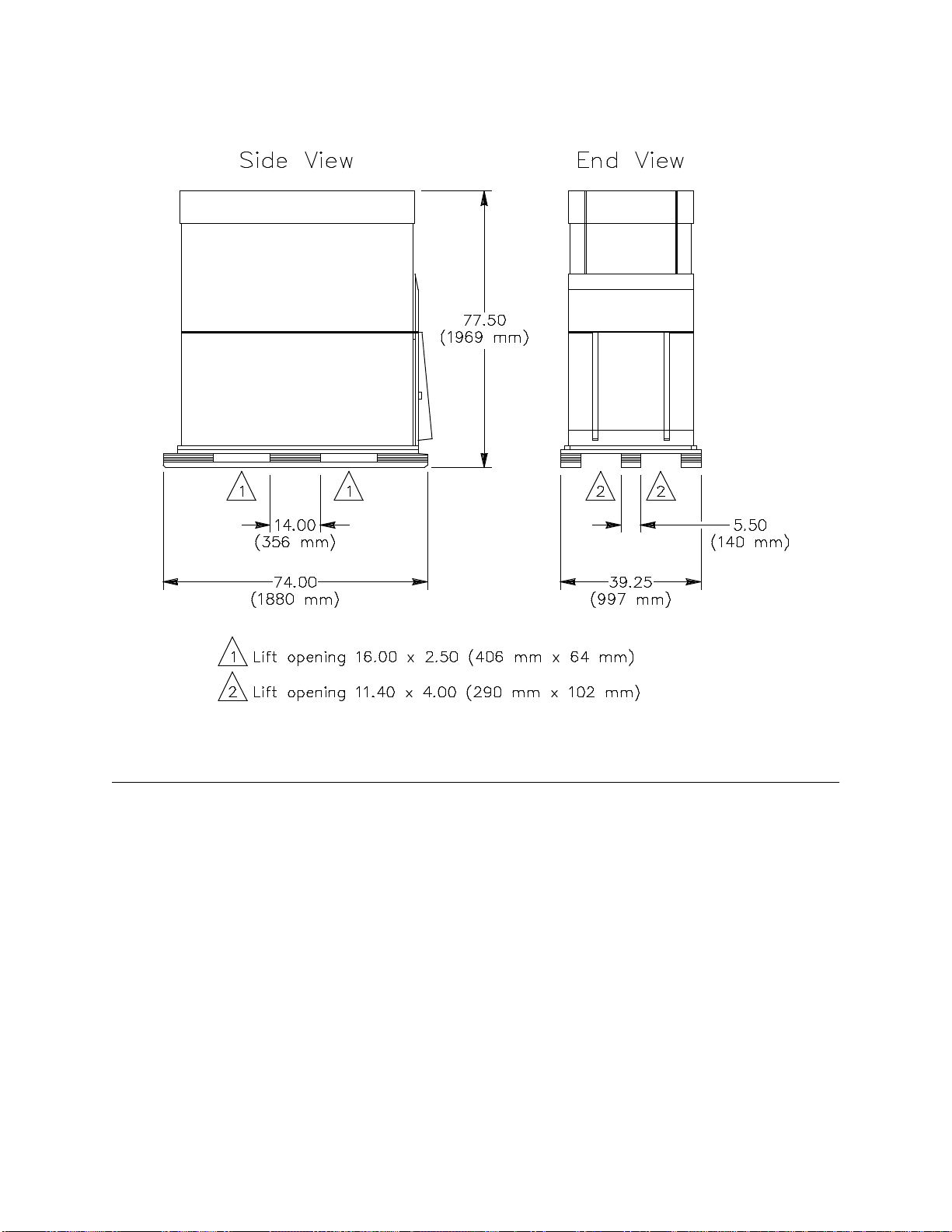
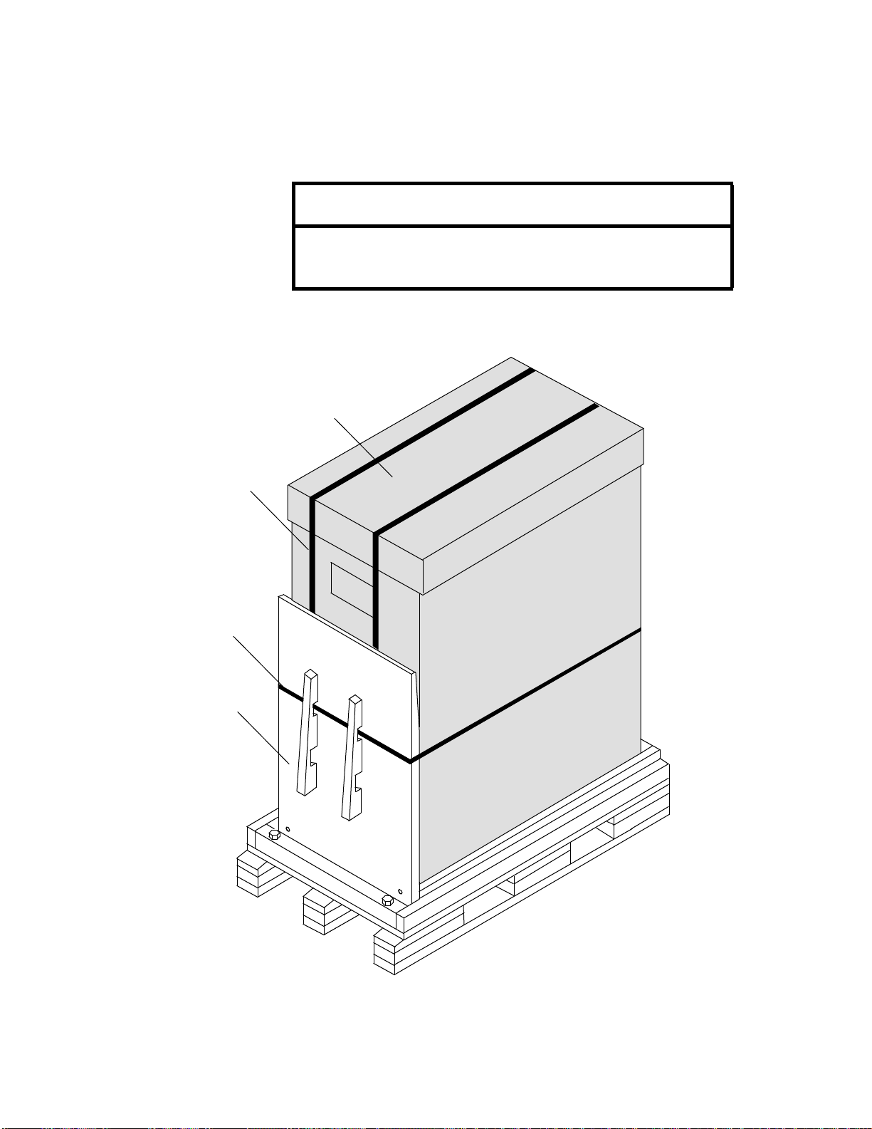
Figure 2showstheCRAY T3E ACcabinetshippingconfiguration,liftopenings,
and dimensions.
CAUTION
Prevent computer equipment from
rolling off the transportation vehicle.
Failure to do so could result in serious
damage to the computer equipment.
Inspecting the System Crates and Boxes CRAY T3E AC System: Single-cabinet Installation
12 CrayResearchProprietary HMM-164-0
Figure 2. CRAY T3E AC Cabinet Shipping Configuration
Inspecting the System Crates and Boxes
The shipping crates contain the mainframe, PC-10, system workstation,
additional system components, and system maintenance and user
documentation. After the system is unloaded from the truck, perform the
following steps before you transport and unpack it.
1. Ensure that the boxes arrived unopened. If any boxes are open, identify
and record the opened boxes through the CRUISE system.
2. Inspect the shipping crate for signs of external damage such as dents,
holes, crushed corners, and water marks. Record any signs of external
damage as an installation defect through the CRUISE system.
CRAY T3E AC System: Single-cabinet Installation Transporting the System to the Designated Location
HMM-164-0 Cray Research Proprietary 13
Transporting the System to the Designated Location
Use pallet jacks to move the system to its designated location. For the crate that
contains the CRAY T3E cabinet, use a regular-length pallet jack (positioned on
the side of the crate) to transport the cabinet. You may also use a long pallet jack
(approximately 60 in. [152 cm]) positioned on the end of the crate. If necessary,
you may use regular-length pallet jacks at each end of the crate to move the
cabinet a short distance. Follow any instructions that are printed on the crates.
Cray Research recommends that you leave each system cabinet in its shipping
crate until it reaches its final location. If the crate does not fit through the
planned access route, you may need to partially disassemble the crate.
The entire route to the computer room should meet the following requirements:
•Floor loading: maximum weight per cabinet is 1,640 lbs (744 kg)
•Minimum door height: 78.75 in. (2,000 mm)
•Minimum door width: 40.00 in. (1,016 mm)
•Maximum incline: 10 degrees (height:length = 1:6)
Refer to the appropriate installation documents for details on other equipment.
Opening the “OPEN FIRST” Box
To ensure that you have the most accurate information available, use the
installationdocumentsfromthe“OPENFIRST”boxtocompletetheinstallation.
This box contains up-to-date versions of this document and associated
installationdocuments.Thisboxalsoincludesthe followingdocumentsthatyou
will refer to during the installation:
•System configuration documentation
•System deviation documentation
•Cable list
CAUTION
Donotapplyfloorplatingoveropenfloor
tiles. Unsupported floor plating could
collapse under heavy equipment and
result in damage to the equipment.

Unpacking the CRAY T3E AC Cabinet CRAY T3E AC System: Single-cabinet Installation
14 CrayResearchProprietary HMM-164-0
Unpacking the CRAY T3E AC Cabinet
If the system shipping or storage environment is significantly colder than the
environment in which it is to be installed [40 °F (22 °C) or greater disparity],
leave the system cabinets in their shipping crates for at least 24 hours at room
temperature before you start the installation. This acclimation prevents damage
to the equipment that could result from thermal shock and condensation.
Afteryoumovethesystemtoitsdesignatedlocation,usethefollowingprocedure
to unpack the mainframe shipping crate and to carefully roll the mainframe off
the pallet ramp. As you unpack the system, check the contents of each shipping
crate against the packing list, which is attached to the outside of the shipping
crate.
NOTE: This procedure applies to CRAY T3E AC mainframes only. To
obtain unpacking procedures for additional system equipment, refer
to the installation documents that are specific to that equipment.
1. Locate the front of the shipping crate; it is marked FRONT. The ramp is
attached to the front of the crate. (Figure 3 shows the shipping crate.)
2. Cut the vertical straps that hold the cardboard shipping panels in place.
These straps are tight and may snap when you cut them.
CAUTION
Steps 1 through Step 19 require two people to ensure
personal safety and to protect the equipment. Failure
to use two people could result in injury to personnel
or damage to the equipment.
CAUTION
The restraining straps are tight and may hit you or
someone nearby when you cut them. Wear eye
protection and protect your body and face when you
cut the straps. Ensure that other personnel either
standclearorprotectthemselves.Failuretodosomay
result in injury.
CRAY T3E AC System: Single-cabinet Installation Unpacking the CRAY T3E AC Cabinet
HMM-164-0 Cray Research Proprietary 15
3. While someone holds the ramp, cut the horizontal strap.
NOTE: The ramp may be positioned as shown below or upside down.
Figure 3. Cabinet Shipping Crate
CAUTION
Someone must hold the ramp when you cut the strap.
Failure to do so may cause the ramp to fall and result
in injury to personnel.
Wooden Ramp
Horizontal Strap
Front
Vertical Strap
Cardboard Cover
Unpacking the CRAY T3E AC Cabinet CRAY T3E AC System: Single-cabinet Installation
16 CrayResearchProprietary HMM-164-0
4. Set the wooden ramp aside temporarily.
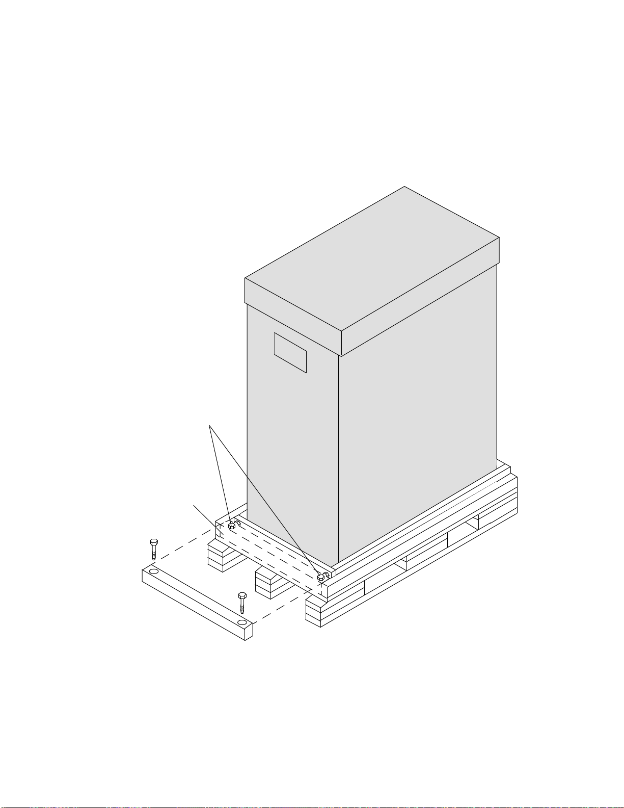
5. With an 11-mm wrench, remove the 2 retaining screws that secure the
retaining block to the shipping crate, then remove the block, as shown in
Figure 4. Retain the screws for the next step.
Figure 4. Retaining Block and Screws
Retaining Block
Retaining Screws
Front
CRAY T3E AC System: Single-cabinet Installation Unpacking the CRAY T3E AC Cabinet
HMM-164-0 Cray Research Proprietary 17
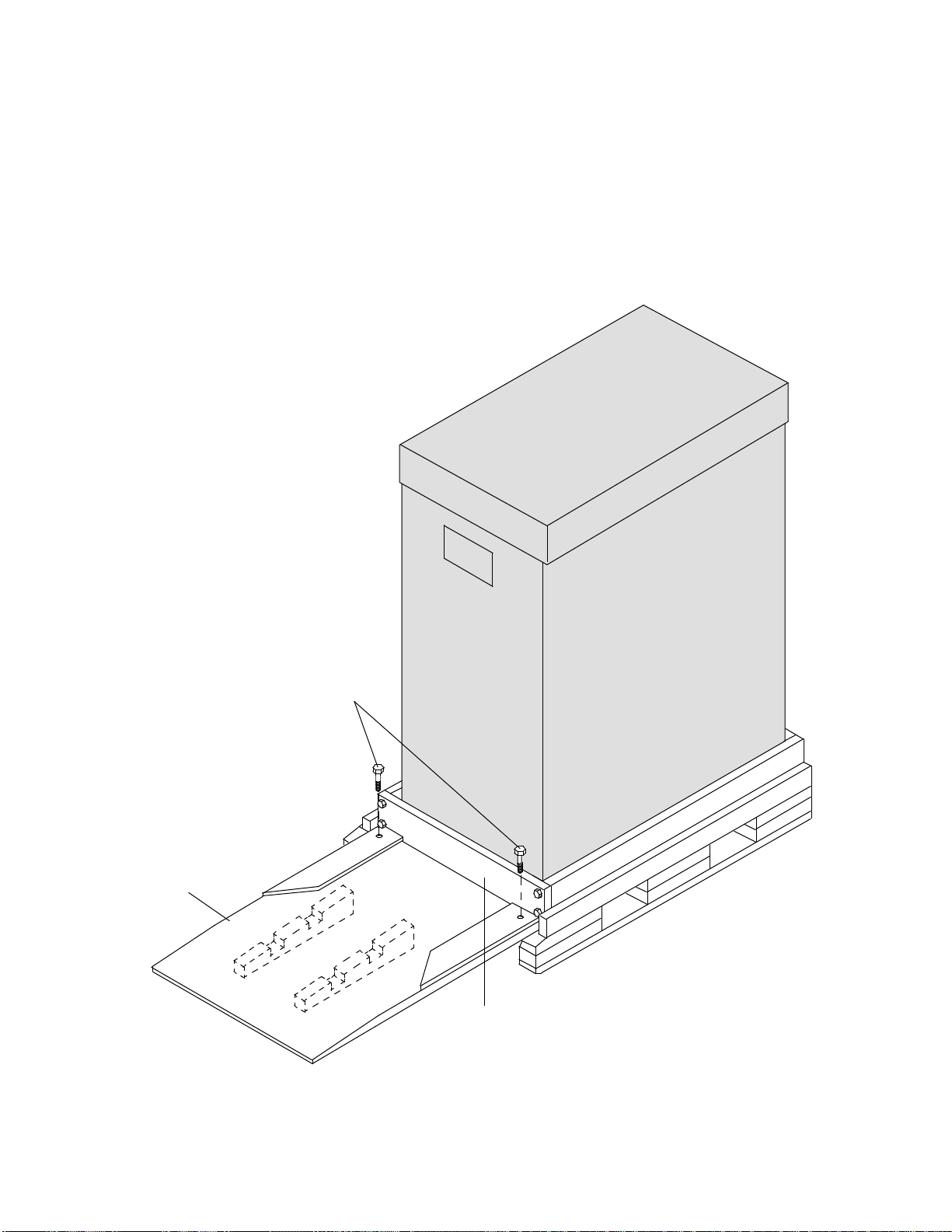
6. Use the following procedure to install the wooden ramp:
a. Position the ramp as shown in Figure 5, so that the screw holes on the
ramp align with the holes on the pallet.
b. Insert the screws that you removed in Step 5 through the holes.
Figure 5. Installing the Ramp
Front
Wooden
Ramp
Inside Retaining Bar
THISSIDEUP
Retaining Screws
RAMP
Unpacking the CRAY T3E AC Cabinet CRAY T3E AC System: Single-cabinet Installation
18 CrayResearchProprietary HMM-164-0
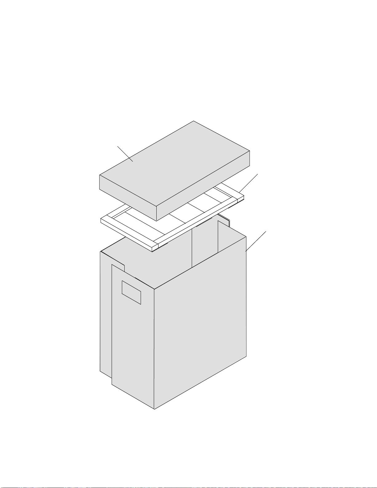
7. Remove the cardboard cover from the top of the shipping crate.
8. Remove the two U-shaped side panels from the crate by lifting up and
then out. Refer to Figure 6.
9. If applicable, remove any additional cardboard panels from the crate.
Figure 6. Cardboard Shipping Container
Foam Pad
U-shaped
Side
Panels
Front
Cover

CRAY T3E AC System: Single-cabinet Installation Unpacking the CRAY T3E AC Cabinet
HMM-164-0 Cray Research Proprietary 19
10. Remove the foam pad from the top of the cabinet; the pad is a single unit.
If there is any padding on the side of the cabinet, remove the padding.
11. Use an 11-mm wrench to remove the inside retaining bar. Four screws
secure the bar to the shipping crate as shown in Figure 7.
Figure 7. Removing the Inside Retaining Bar
Inside Retaining Bar
Front
Unpacking the CRAY T3E AC Cabinet CRAY T3E AC System: Single-cabinet Installation
20 CrayResearchProprietary HMM-164-0
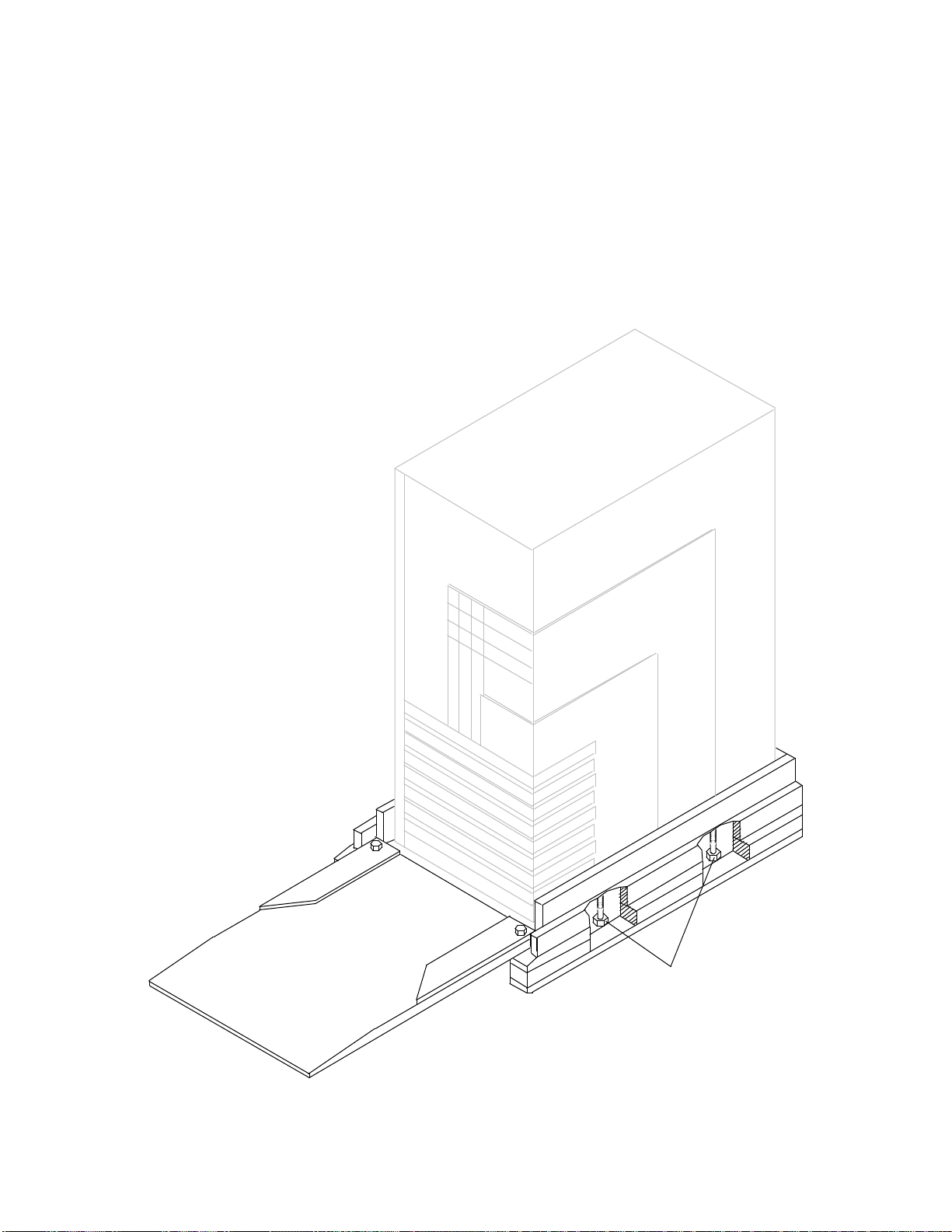
12. Use an adjustable wrench (or a 16-mm wrench) to remove the 4 shipping
bolts that secure the cabinet to the pallet. To access them, reach under the
shipping pallet between the floor pads. There are 2 bolts (with washers)
on each side of the pallet. Refer to Figure 8.
13. Ensure that the cabinet levelers (legs) are raised completely and, if
possible, ensure that the front casters (wheels) face the ramp.
Figure 8. Shipping Bolts
Shipping Bolts
Front
Other manuals for T3E
2
Table of contents
Popular Air Conditioner manuals by other brands

Sanyo
Sanyo KS2432 instruction manual

Mitsubishi Electric
Mitsubishi Electric PUHZ-RP50VHA4 Service manual

Mitsubishi Electric
Mitsubishi Electric PLA-M100EA installation manual

NuAire
NuAire UNI-X Series installation manual

Dometic
Dometic MCS T6 operating manual

Panasonic
Panasonic CS-KE12NB41 installation instructions


