NuAire UNI-X Series User manual

1
17. 06. 20. Document Number 671789Nuaire | Western Industrial Estate | Caerphilly | CF83 1NA |nuaire.co.uk
UNI-X
Supply & Extract With Heat Recovery
Installation Manual
EMC Directive
2014/30/EU
LVD Directive
2014/35/EU
1.0 SAFETY INFORMATION
• The provision of the electrical supply and the connection of the unit to the mains must be
carried out by a qualified electrician.
• Isolate from power supply before removing any covers. During installation / maintenance ensure
all covers are fitted before switching on the mains supply.
• All-pole disconnection from the mains as shown in the wiring diagram must be incorporated
within the fixed wiring and shall have a minimum contact separation of 3mm in accordance with
latest edition of the wiring regulations.
• This unit must be earthed.
• Ducting must be securely fixed with screws to the spigot to prevent access to live parts. Duct
runs terminating close to the fan must be adequately protected by suitable guards.
• If the supply cord is damaged, it must be replaced by the manufacturer, its service agent or
similarly qualified persons in order to avoid a hazard.
• Precautions must be taken to avoid the back-flow of gases into the room from the open flue of
gas or other fuel-burning appliances.
• This appliance should not be used by children or persons with reduced physical, sensory or
mental capabilities or lack of experience and knowledge, unless they have been given supervision
or instruction concerning the safe use of the appliance by a person responsible for their safety.
Children shall not play with the appliance. Cleaning and user maintenance shall not be carried
out by children.
1.1 Symbols
GENERAL WARNING
Signifies a general warning regarding hazard specified by supplementary information.
ELECTRIC SHOCK
This unit must be completely electrically isolated before any panels are removed. Check
mains supply and control connections.
ROTATING PARTS
This unit contains fast moving rotational parts which may start automatically. It is the
sole responsibility of the installer to adequately guard these components.
REFER TO INSTRUCTION MANUAL
Read and understand the installation and maintenance manual before installing,
operating or maintaining this product.

2
17. 06. 20. Document Number 671789Nuaire | Western Industrial Estate | Caerphilly | CF83 1NA |nuaire.co.uk
UNI-X
Installation Manual
1.2 Important Information
This manual contains important information on the safe and
appropriate assembly, transport, commissioning, operation,
maintenance, disassembly and simple troubleshooting of the product.
While the product has been manufactured according to the accepted
rules of current technology, there is still a danger of personal injury or
damage to equipment if the following general safety instructions and
the warnings contained in these instructions are not complied with.
•Read these instructions completely and thoroughly before
working with the product.
•Keep these instructions in a location where they are accessible
to all users at all times.
•Always include the operating instructions when you pass the
product on to third parties.
1.3 Personal Protective Equipment
The following minimum Personal Protective Equipment (PPE) is
recommended when interacting with Nuaire product:
•Protective Steel Toed Shoes - when handling heavy objects.
•Full Finger Gloves (Marigold PU800 or equivalent) - when
handling sheet metal components.
•Semi Fingerless Gloves (Marigold PU3000 3DO or equivalent)
- when conducting light work on the unit requiring tactile
dexterity.
•Safety Glasses - when conducting any cleaning/cutting operation
or exchanging filters.
•Reusable Half Mask Respirators - when replacing filters which
have been in contact with normal room or environmental air.
Nuaire would always recommend a site specific risk assessment by a
competent person to determine if any additional PPE is required.
2.0 INTRODUCTION
The UNI-X ceiling void unit range is designed to provide mechanical
supply and extract ventilation with heat recovery, which incorporates an
automatic HX bypass feature.
The units are fitted with two high efficiency centrifugal fans with EC Motors,
which have speed control over three different ventilation rates; trickle, boost and
max. A counterflow plate heat exchanger is also used to recover up to 85% of
the extracted air heat, whilst G3 Filters provide protection to the unit and ensure
filtered air is supplied, guaranteeing the unit is ErP 2018 compliant.
The HX bypass damper shall open automatically via a wax actuator allowing the
air to bypass the heat exchanger to deliver fresh filtered air during the warmer
months.
General information regarding performance and specifications for the
equipment may be obtained from our Technical Literature, and/or project
specific documentation.
2.1 Code Description:
UNI - X 220 - C
1-23-4
1. Range: Student Accommodation
2. HX Type X = Plate Heat Exchanger
3. Unit Size: 220, 360, 580
4. Spigot Type: No Suffix = Rectangular (220 x 90mm)
C = Circular (150mm Ø)
3.0 MECHANICAL INSTALLATION
The UNI-X ceiling void unit range is designed to provide mechanical
supply and extract ventilation with heat recovery, which incorporates an
automatic HX bypass feature.
The units are fitted with two high efficiency centrifugal fans with EC Motors,
which have speed control over three different ventilation rates; trickle, boost and
max. A counterflow plate heat exchanger is also used to recover up to 85% of
the extracted air heat, whilst G3 Filters provide protection to the unit and ensure
filtered air is supplied, guaranteeing the unit is ErP 2018 compliant.
The HX bypass damper shall open automatically via a wax actuator allowing the
air to bypass the heat exchanger to deliver fresh filtered air during the warmer
months.
General information regarding performance and specifications for the
equipment may be obtained from our Technical Literature, and/or project
specific documentation.
3.1 Delivery of Equipment
3.1.1 Receipt of Equipment
All equipment is inspected prior to despatch and leaves the factory in
good condition. Upon receipt of the equipment an inspection should be
made and any damage indicated on the delivery note.
Particulars of damage and/or incomplete delivery should be endorsed
by the driver delivering the goods before offloading by the purchaser.
No responsibility will be accepted for damage sustained during the
offloading from the vehicle or on the site thereafter. All claims for
damage and/or incomplete delivery must be reported to Nuaire within
two days of receipt of the equipment following guidance in our terms &
conditions of sale.
3.1.2 Offloading and Handling
The weight of the unit modules and palletised items is displayed on
the unit rating plate or on the packaging. Some of the modules have an
uneven weight distribution, and this will be indicated by labelling where
appropriate. Ensure that lifting and handling equipment is adequately
rated. Offloading and positioning of the equipment is the responsibility
of the purchaser.
Spreaders should be used when lifting with slings to avoid damage
to the casings. Care must be taken to ensure that slings are correctly
positioned to avoid crushing and twisting of the unit castings.
Where channels and/or support frames are bolted to the underside of
the unit casing, slings or fork-lift arms should be positioned to locate in
the apertures in the channels. If lifting eyes have been supplied / fitted
it is recommended that they are used.
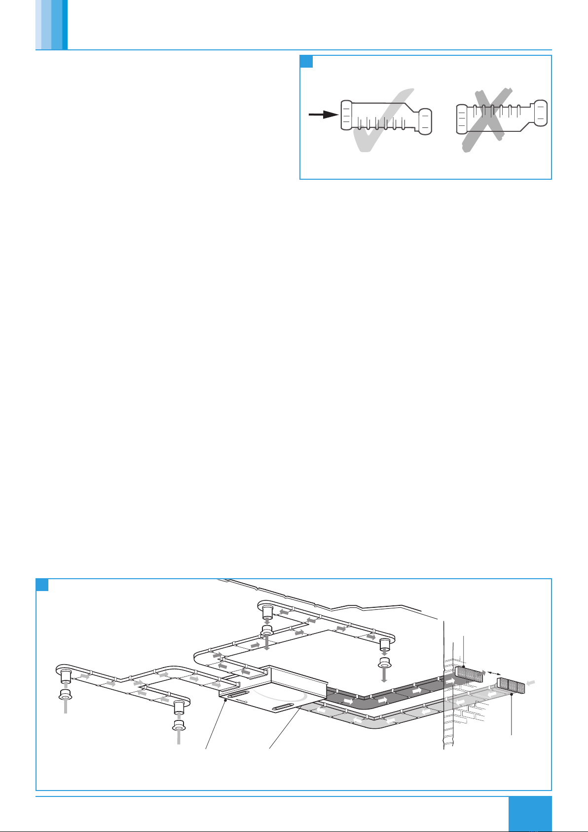
UNI-X units will be delivered to site in one section and will be labelled
with the direction of air flow. The direction convention must be
observed during assembly.
3.1.3 Storage
The equipment must be stored in a dry, internal location. Ductwork
connection apertures shall be sealed against the ingress of dust, water
and vermin. Do not stack units, modules or components.
Where fans are to be stored or bonded for extensive periods follow the
Warranty Guidance Notes found in our conditions of sale.
3.2 Unit Installation
Installation of the UNI-X units, including all external services and
controls should be installed in accordance with the appropriate site
procedures, and MUST conform to all governing regulations e.g.
CDM, CIBSE, IEE, and in strict accordance with the applicable Building
Regulations.
To aid in installation, dimensional templates including hole centres
for mounting points are provided with the units.

3
17. 06. 20. Document Number 671789Nuaire | Western Industrial Estate | Caerphilly | CF83 1NA |nuaire.co.uk
UNI-X
Installation Manual
Supply air to
lounge via
in ceilings.
Air Valve
Extract air from
kitchen via
in ceilings.
Air Valve
Supply air to
bedrooms via
in ceilings.
MVHR-DRAIN
Air Valve
condensate drain,
with min 5° fall running
to SVP (obscured by unit).
Nuaire ceiling void
mounted unit.
Extract air from
bathroom via
in ceilings.
Air Valve
Exhaust air from
kitchen/bathroom to
outside via air brick.
Supply and extract
ducts from external
air bricks to the unit
needs to be insulated.
Top of ceiling void.
Minimum distance as
specified in Building
Regulations.
Intake air from
outside via air brick.
The unit must be installed indoors, in a suitable ceiling void away from
direct sources of frost, heat and water spray or moisture generation. For
a vibration-free result the unit must be mounted to a solid surface in
the void.
The unit is designed for ceiling mounting on a horizontal surface and
incorporates steel mounting points (fixings are not supplied) in the
casing design as well as bottom access for filter replacement.
The unit may only be operated in its intended horizontal
installation plane and must be fully levelled during installation
(this is essential to ensure that condensate drains correctly).
Offset spigots have been included in the unit for greater flexibility in
the layout of the ductwork.
The correct installation position for the units shall be decided with due
regard to access and maintenance requirements, and the objective of
minimising the system ductwork resistance.
The recommended installation method is to use standard Unistrut
channel secured to the slab or steelwork above the unit. Six suitable
drop rods or bolts should be secured to the Unistrut channel and
extended to be fixed to the unit’s two mounting brackets (one on each
side of the unit, each with 3 fixing points).
In the unlikely event of motor failure, the unit must be lowered from
its installation position in order to facilitate a motor replacement. An
access hatch of sufficient size for the unit to pass through is required.
You must ensure that all associated electrical, condensate and
ductwork connections can be disconnected.
The unit must be installed with a minimum of 300mm clearance
around the control box to allow for maintenance. An access hatch of
sufficient size for the unit to pass through is required.
3.3 Condensate Drain
Units come complete with external drain pipe (21.5mm waste pipe) at
the front of the unit. Use conventional plumbing connections to link up
with U-trap or alternative drain method (Solvent cement connections
or compression fit connections are recommended). The condensate
must be discharged under a water level in a U-trap drainpipe or an
alternative drain method which acts as an airlock. If using a U-trap,
ensure the U-trap has been filled to a suitable level of water to provide
an adequate airlock.
This condensate discharge connection is suitable for 21.5mm diameter
overflow pipe. Solvent cement should be used to make the joint. If the
condensation pipe is fitted in an unheated space the pipe should be in
insulated to prevent freezing. Ensure that the condensate drain pipe has
a minimum 5° fall running to SVP.
CORRECT INCORRECT
Flow
Side elevation
When installed horizontally the ribs must be at the bottom to
ensure correct operation.
1
2
MVHR-DRAIN Installation
Typical Ducting Arrangement
Nuaire recommend MVHR-DRAIN be used as the primary
condensate take-off.
3.3.1 MVHR-DRAIN Installation
Offer up the MVHR-DRAIN inlet to the threaded tail of the appliance
waste outlet or MVHR-DRAIN knuckle or running adaptor, and tighten
the threaded cap sufficiently hand-tight to provide a water-tight seal
(check that the cap screws on square and does not ‘cross-thread’).
When the screwed cap is tight, the MVHR-DRAIN body is secure.
1. Cut the pipe to length, allowing for the full compression socket
depth (using an appropriate pipe cutter, such as a Hepworth ratchet
pipe cutter).
2. Remove any ‘swarf’ from the end of the plastic pipe. Ream the
copper pipe end to remove any ‘burr’, and file if necessary to remove
any external sharp edges. Mark the socket depth on the pipe, and
check that the pipe section to be jointed is free of any surface
damage which may affect the joint seal.
3. Unscrew the cap from the MVHR-DRAIN outlet, and slide the cap
and rubber seal onto the pipe.
4. Insert the pipe end fully into the socket.
5. Slide the rubber seal and screwed cap up against the face of the
socket, and tighten the cap sufficiently hand-tight (check that the
cap is square to the body and does not ‘cross thread’). Hand tight
should be adequate to form a proper seal.
3.4 Extract / Supply Areas
The unit is designed to extract air from all wet rooms e.g. bathroom,
kitchen, en-suite, utility room (with sink). WC’s do not need to be
ventilated if openable windows are fitted.
Supply air should be to all habitable rooms e.g. bedrooms and lounge.
Extract / input grilles should be adjustable valve types (not supplied).

4
17. 06. 20. Document Number 671789Nuaire | Western Industrial Estate | Caerphilly | CF83 1NA |nuaire.co.uk
UNI-X
Installation Manual
3.5 Ducting
It is recommended that rigid ducting should be used at all times.
Flexible ducting has a very high resistance and it is impossible to
calculate how much resistance will be on a system if used. If used the
flexible ducting must be kept to a minimum and should always be
pulled taut. A maximum of 300mm should be used on each leg.
To prevent condensation on the outside of the outside air inlet duct and
the air outlet duct from the UNI-X, these ducts should be insulated.
Ducting must be installed in such a way that resistance to airflow is
minimised. Bends should be kept to a minimum. A minimum distance
of 300mm between the appliance and any bends in ductwork is
recommended. 220 x 90mm rectangular ducting should be used (Figure
2). Ducting joints must be sealed with non-hardening silicone type
sealant and needs to be taped with metallised tape. Ducting shall be
adequately and reliably fixed to the appliance.
3.6 Dimensions (mm) & Weights (kg)
3.6.1 Rectangular Spigot Units (UNI-X220, UNI-X360 & UNI-X580
Unit Code Unit Dimensions (mm) Unit Weights
(kg)
A B C D E F G H J K L M
UNI-X220 570 980 300 982 71 132 57 142 64 75 57 152 40
UNI-X360 720 1072 300 1100 53 163 53 130 57 160 53 194 55
UNI-X580 985 1136 300 1216 60 233 52 103 60 243 52 268 65
F
E
H
G
C
D
A
B
Plan View
K
J
M
L
Condensate Pipe
Connection
Bottom Access
for Filters
Exhaust
Intake
Room
Extract
Room
Supply
Condensate Pipe
Connection
Room
Extract
End View (Atmosphere Side)
End View (Room Side)
Side View
Unit Code Hole Centre Dimensions (mm)
N P Q R
UNI-X220 934 524 262 467
UNI-X360 1031 670 335 515
UNI-X580 1091 938 469 546
P
Q
RN
Plan View
Condensate
Pipe Connection
3
4
Rectangular Spigot Unit Dimensions & Weights
Rectangular Unit Mounting Hole Centres Dimensions

5
17. 06. 20. Document Number 671789Nuaire | Western Industrial Estate | Caerphilly | CF83 1NA |nuaire.co.uk
UNI-X
Installation Manual
Unit Code Unit Dimensions (mm) Unit Weights
(kg)
A B C D E F G H J K L M
UNI-X220 570 980 300 982 71 132 57 142 64 75 57 152 40
UNI-X360 720 1072 300 1100 53 163 53 130 57 160 53 194 55
UNI-X580 985 1136 300 1216 60 233 52 103 60 243 52 268 65
Unit Code Hole Centre Dimensions (mm)
N P Q R
UNI-X220-C 934 524 262 467
UNI-X360-C 1031 670 335 515
UNI-X580-C 1091 935.6 467.8 546
P
Q
RN
Plan View
Condensate
Pipe Connection
5
6
Circular Spigot Unit Dimensions & Weights
Circular Spigot Unit Mounting Hole Centres Dimensions
3.6.2 Circular Spigot Units (UNI-X220-C, UNI-X360-C & UNI-X580-C
Condensate Pipe
Connection
Bottom Access
for Filters
Exhaust
Intake
Condensate Pipe
Connection
Room
Extract
Room
Supply
Side View
End View (Atmosphere Side)
H
G
F
E
End View (Room Side)
K
J
M
L
A
B
Plan View
D
C

6
17. 06. 20. Document Number 671789Nuaire | Western Industrial Estate | Caerphilly | CF83 1NA |nuaire.co.uk
UNI-X
Installation Manual
MAINS
230V
50Hz
Room
lights
Light
(Double
switches
Pole)
N
L
3 Pole
isolator
Kitchen switch
Blue
Green/yellow
Brown
Black
Supply cord
from unit
Optional boost switch
Grey
MAINS
230V
50Hz
light
Room
Light
(Double
switch
Pole)
N
L
3 Pole
isolator
Kitchen switch
Blue
Brown
Black
Optional boost switch
Supply cord
from unit
Grey
Green/yellow
4.0 ELECTRICAL INSTALLATION
The electrical wiring should be carried out by competent persons, in
accordance with industry practises and in conformance to all governing
and statutory bodies.
For good EMC engineering practice, any sensor cables or switched live
cables should not be placed within 50mm of other cables or on the
same metal cable tray as other cables.
Unit details including Full Load Current, Voltage, fan speed etc. can be
found on the unit label.
The UNI-X range of units MUST be earthed.
The five core cable from the mains power supply should be connected
to a fixed wiring installation, via a fused isolator, in accordance with
current IEE wiring regulations.
In the event of an ESD discharge while operating the optional touch
switch, the fan control may reset itself causing the fans to switch off
temporarily. Functions will resume as normal after the control resets.
4.1 Electrical Information
Electrical details:-
Voltage: 240V 1ph 50Hz
4.2 Wiring diagrams
4.2.1 PCB
Unit Code Power Consumption (W) Full Load Current (A)
UNI-X220(-C) 168 1.5
UNI-X360(-C) 168 1.5
UNI-X580(-C) 340 2.8
CN11 & CN12 NET
connections for
Ecosmart devices
6 pre-set potentiometer’s
controlling individual fan
speed for the different speed
settings.
Note: Wiring is for reference
purposes only, as the
connections are factory fitted.
The unit is pre-wired with a 2
metre fly lead.
BYPASS
EXTRACT FAN
EXTRACT
SUPPLY FAN
SUPPLY
BLU
YEL
WHI
RED
BLU
YEL
WHI
RED
TH1 TH2
7
8
9
PCB Diagram
Unit Serving Kitchen & Bathroom Wiring Diagram
Unit Serving Kitchen and Multiple Bathrooms Wiring Diagram
4.2.2 Unit Serving Kitchen & Bathroom
4.2.3 Unit Serving Kitchen and Multiple Bathrooms
Disconnection from the supply
mains must be incorporated
within the fixed wiring in
accordance with the wiring
regulations and shall have a
minimum contact separation of
3mm.
Disconnection from the supply
mains must be incorporated
within the fixed wiring in
accordance with the wiring
regulations and shall have a
minimum contact separation of
3mm.
When wiring a unit that serves
multiple bathrooms, the wiring
shown as a dashed line can be
repeated for the appropriate
number of bathrooms.

7
17. 06. 20. Document Number 671789Nuaire | Western Industrial Estate | Caerphilly | CF83 1NA |nuaire.co.uk
UNI-X
Installation Manual
5.0 CONTROLS
5.1 Optional Control Ancillaries
The following list of control ancillary items have been tested and are
available for use with UNI-X units:
Ancillary Code Description
ES-JB Ecosmart Junction Box
ES-HUMIDSTAT2 Ecosmart Surface Mounted Humidistat
ES-THERMOSTAT2 Ecosmart Surface Mounted Thermostat
ES-PIR2 Ecosmart Surface Mounted Passive InfraRed Sensor
ES-AVI2 Ecosmart Surface Mounted Audio Visual Indicator
ES-VF Ecosmart Surface Mounted Vault Free Relay Box
230-PIR 230V Passive InfraRed Sensor
779891 Normal or Boost Speed Switch
MRXBOX95-3SWITCH 3 Speed Switch
UNI-X-BT Illuminated Push Button Run-On Timer
UNI-X-TT Illuminated Touch Button Run-On Timer
5.2 Status Indication
The status of the unit is indicated by a series of LED’s on the front cover,
with variations listed below.
5.3 Frost Protection
In the event of the intake air temperature at the unit dropping below
the predetermined set point (-5°C as standard) the supply fan will
reduce to minimum speed, once the temperature rises above the set
point the fan will return to its commissioned speed.
Please note this mode will only activate after ten days of continuous
run time. If commissioning of the unit is outside of this time frame
please notify the after sales department prior to site visit.
5.4 Heat Exchanger Bypass
The HX bypass damper shall open automatically under certain
scenarios allowing the supply air to bypass the heat exchanger. These
scenarios are described below.
1. Outdoor temp >10°C
AND
Indoor temp > Outdoor temp
AND
Inside temp > 25°C
11 Commissioning Controls
2. Outdoor temp > 10°C
AND
Outdoor temp > Indoor temp
AND
Outdoor temp < 25°C
An amount of hysteresis is included in the strategy such that the
"current" condition is maintained until 1°C past the control point.
5.5 Commissioning
The unit is supplied with independent fan speed control via the
potentiometers (Figure 7) for both normal and boost and maximum
airflows.
Commissioning should be carried out in accordance with building
regulations document “domestic ventilation compliance guide”.
A calibrated moving vane anemometer and hood will be required for
the commissioning, and adjustment valves should be locked in place to
prevent further adjustment.
Once commissioned the unit should not be adjusted as it will have
a detrimental effect on the indoor air quality and could result in
condensation and mould growth. The label covering the control has
an adhesive panel which should be removed post commissioning to
prevent tampering.
10 Status Indication LED's
HX Bypass
(AB units only)
Speed 1
Speed 2
Speed 3
Supply Fan Fault
Extract Fan Fault
Frost Protection
Filter Change
+
- -
+
-
+
-
+
-
+
Power
Post commissioning remove
adhesive backing under
this section
060905
Ventilation Controls
For commissioning:
refer to user manual
+
-
Control module
6.0 MAINTENANCE
It is important that maintenance checks are recorded and that the
schedule is always adhered to, in all cases, the previous report should
be referred to.
6.1 Maintenance Schedule
6.1.1 Routine Maintenance
•Clean all areas of unit and treat any areas of corrosion.
•Check all access doors for leakage and if necessary locks should be
adjusted and any replacement gasket materials should be replaced
as required.
•Any drain trays should be cleaned and repaired if necessary.

8
17. 06. 20. Document Number 671789Nuaire | Western Industrial Estate | Caerphilly | CF83 1NA |nuaire.co.uk
UNI-X
Installation Manual
5. Unscrew all bolts and screws from the newly exposed EPS foam lid
and remove foam lid. This allows access to replace the unit motors.
6. Once motor replacement has been completed reassemble the
unit in reverse operation to the process described above. Ensure all
fixings are replaced and secure prior to testing the unit.
7.0 WARRANTY
The 2year warranty starts from the day of delivery and includes parts
and labour for the first year. The remaining period covers replacement
parts only.
This warranty is void if the equipment is modified without
authorisation, is incorrectly applied, misused, disassembled, or not
installed, commissioned and maintained in accordance with the details
contained in this manual and general good practice.
The product warranty applies to the UK mainland and in accordance
with Clause 14 of our Conditions of Sale. Customers purchasing from
outside of the UK should contact Nuaire International Sales office for
further details.
Failure to maintain the unit as recommended will invalidate the
warranty.
8.0 END-OF-LIFE AND RECYCLING
Where possible Nuaire use components which can be largely recycled
when the product reaches its end-of-life:
•Fans, motors, controls, actuators, cabling and other electrical
components can be segregated into WEEE recycling streams.
•Sheet metal parts, aluminium extrusion, heating/cooling coils and
other metallic items can be segregated and fully recycled.
•EPP, plastic ducting, nylon corner pieces, plastic heat exchangers,
packaging material and other plastic components can be
segregated into mixed plastic and widely recycled.
•Cardboard packaging, wood, used filters and other paper
components can be largely recycled or fully processed in energy
from waste centres.
•Remaining Items can be further segregated and processed in
accordance with the zero waste hierarchy. Please call After Sales
Support for further information on items not listed above.
IMPORTANT
Ensure that Nuaire product is made safe from any electrical
/ water / refrigerant supplies before dismantling commences.
This work should only be undertaken by a qualified person in
accordance with local authority regulations and guidelines,
taking into account all site based risks.
9.0 AFTER SALES AND REPLACEMENT PARTS
For technical assistance or further product information, including spare
parts and replacement components, please contact the After Sales
Department.
If ordering spares please quote the serial number of the unit together
with the part number, if the part number is not known please give a full
description of the part required. The serial number will be found on the
identification plate attached to the unit casing.
Telephone 02920 858 400
aftersales@nuaire.co.uk
6.1.2 Every 3 Months
•Check filters and change/clean if required, failure to do so may
impair the performance and energy efficiency of this unit.
•Ensure condensate drains are cleaned clear and that water can
flow freely from unit.
•Check fin coil banks and heat exchangers. If necessary clean with a
soft brush or vacuum. Check for signs of contamination.
6.1.3 Annually
•Thoroughly inspect the unit and its components for corrosion,
acting immediately to treat/restore any damaged areas.
•All electrical terminals within the unit should be tightened.
•Check all earth connections.
6.2 Filter Replacement
Filters can be accessed within the unit by removing the two filter covers
on the bottom panel of the unit. Take hold of the two circular tabs
either end of the filter covers and pull to remove (see Figure 7).
The filter can now be extracted by pulling the removal loop on the edge
of the filter. Once the filters have been inspected and return or replace
them as necessary and refit the filter cover.
To fit the filter cover, insert both ends of the cover into the filter slot
and press down on the centre (see Figure 8). Ensure that a full seal is
made between the unit and the cover. Any incorrectly fitted covers will
cause a performance drop of the unit.
6.3 Motor Replacement
With the unit taken down from its installed position, the motors can be
replaced by following the below procedure:
1. Unscrew all the black plastic Expanded Polystyrene (EPS) fixings in
the top, sides and ends of the unit using a Torx Driver Bit, T25 x 70
mm (RS component no. 769-119).
2. Unscrew the three screws at the top of both end panels; this will
release the top plate of the unit.
3. Remove the earth fixing that connects the top plate to the unit
control panel.
4. Remove the top plate of the unit, lifting directly upwards using the
safety edges along the side of the top plate.
1
1
2
12 Fitting Filter Cover
This manual suits for next models
6
Table of contents
Other NuAire Air Conditioner manuals
Popular Air Conditioner manuals by other brands

Retro Aire
Retro Aire R30C Installation, operation & maintenance manual

Gree
Gree GWH18TC-K3DNA1B/I Service manual

Mitsubishi Heavy Industries
Mitsubishi Heavy Industries DXK05ZTLA-WF user manual

Toshiba
Toshiba RAC-PD0811CRU user manual

Mitsubishi Electric
Mitsubishi Electric MSZ-DM25VA operating instructions

Sanyo
Sanyo STB0811C1-S parts list