CREPoW MULTIMIG 400F SYN User manual

THANK YOU FOR USING OUR PRODUCTS
IMPORTANT: Read this Owner’s Manual Completely before attempting to use this
equipment. Save this manual and keep it handy for quick reference. Pay particular
attention to the safety instructions we have provided for your protection. Contact your
distributor if you do not fully understand this manual.
MULTIMIG 400F SYN
INVERTER Based Welding Machines
OPERATORS’ MANUAL

CONTENT
I
CONTENT
§1 Safety······························································································································ 1
§2 Overview ························································································································ 9
§2.1 Features·······························································································································9
§2.2 Technical Data···················································································································10
§2.3 Brief Introduction·············································································································10
§2.4 Duty cycle and Over-heat··································································································11
§2.5 Working Principle·············································································································11
§2.6 Volt-Ampere Characteristic······························································································12
§3 Panel Functions & Descriptions ·················································································· 13
§3.1 Machine Layout Description ····························································································13
§3.1.1 Front and rear panel layout of welding machine··································································· 13
§3.1.2 Front and rear panel layout of water cooling········································································· 14
§3.1.3 Wire feeder······························································································································ 15
§3.2 Front Panel Functions and Descriptions ·········································································15
§3.2.1 Front Panel Functions of welder····························································································· 15
§3.2.2 Front Panel Functions of wire feeder ····················································································· 19
§4 Installation & Operation ····························································································· 22
§4.1 Installation & Operation for MMA Welding·····································································22
§4.1.1 Set up installation for MMA Welding······················································································ 22
§4.1.2 MMA Welding ·························································································································· 23
§4.1.3 MMA Welding Fundamentals·································································································· 24
§4.2 Installation & Operation for TIG Welding ·······································································26
§4.2.1 Set up installation for TIG Welding ························································································ 26
§4.2.2 DC TIG Welding························································································································ 29
§4.2.3 TIG Welding Fusion Technique ······························································································· 30
§4.2.4 Tungsten Electrodes ··············································································································· 31
§4.2.5 Tungsten Preparation ············································································································· 34
§4.3 Installation & Operation for MIG Welding·······································································36
§4.3.1 Set up installation for MIG Welding························································································ 36
§4.3.2 Wire Feed Roller Selection ····································································································· 39
§4.3.3 Wire Installation and Set Up Guide ························································································ 40
§4.3.4 MIG Torch Liner Types and Information················································································ 43
§4.3.5 MIG Welding ···························································································································· 44
§4.4 Set up installation for Spool Gun ·····················································································51
§4.5 Standard welding programs·····························································································54
§4.6 Welding parameters ·········································································································54
§4.7 Operation environment····································································································55
§4.8 Operation Notices ·············································································································56
§5 Welding trouble shooting···························································································· 57
§5.1 MIG welding trouble shooting··························································································57

CONTENT
II
§5.2 MIG wire feed trouble shooting ·······················································································58
§5.3 DC TIG welding trouble shooting ·····················································································59
§5.4 MMA welding trouble shooting························································································61
§6 Maintenance & Troubleshooting ················································································ 62
§6.1 Maintenance······················································································································62
§6.2 Troubleshooting ···············································································································63
§6.3 List of error code···············································································································65
§6.4 Electrical schematic drawing ···························································································66

SAFETY
1
§1 Safety
Notice: The instructions are for reference only. The manufacturer
reserves the right to explain the differences between the description
and the product due to product changes and upgrades!
General
The device is manufactured using state-of-the-art
technology and
according to recognised safety standards. If used incorrectly or misused,
however, it can cause:
Injury or death to the operator.
Damage to the device and other material assets bel
onging to the
operating company.
Inefficient operation of the device.
All persons involved in commissioning, operating, maintaining and
servicing the device must:
Be suitably qualified.
Have sufficient knowledge of welding.
Read and follow these operating instructions carefully.
The operating instructions must always be at hand wherever the device
is being used. In addition to the operating instructions, attention must
also be paid to any generally applicable and local regulations regarding
accident prevention and environmental protection.
Before switching on the device, rectify any faults that could compromise
safety.
This is for your personal safety!
Environment
Products are limited to use under suitable conditions. In extreme cases,
the use of products, such as high temperature, low temperature,
thunderstorm weather, will shorten the life of the machine and even
cause damage, please avoid the above situation.

SAFETY
2
Excessive ambient temperature will cause the machine heat dissipation
is not smooth, so that the internal components of the machine heat
seriously. Usually the maximum operating temperature is 104°F (40°C).
Low temperature may lead to performance degradation or damage of
components insi
de the product, resulting in ice inside the water tank.
Usually the lowest operating temperature is 14°F (-10°C). Please keep
warm and add antifreeze in the water tank if necessary.
Too humid environment may lead to rust of shell and circuit
components. In rainy weather, using products may lead to short circuit
and other abnormalities. Please try to avoid using in the above
environment. If the machine is wet, please dry in time.
Areas
Running parts and specific parts of risk will take damage for your body
or others. The corresponding notices are as follows. It is quite a safe
operation after taking several necessary protection measures.
Items being welded generate and hold high heat and can cause severe
burns. Don’t touch hot parts with bare hands. Al
low a cooling period
before working on the welding gun. Use insulated welding gloves and
clothing to handle hot parts and prevent burns.
A high risk of injury exists when the welding wire emerges from the
welding torch. Always keep the torch well away from the body.
Keep all equipment safety guards, covers and devices in position and in
good repair. Keep hands, hair, clothing and tools away from V-gears,
fans and all other moving parts when starting, operating or repairing
equipment, for example:
Fans
Cogs
Rollers
Shafts
Wire spools and welding wire
SAFETY
3
By product
Many harmful phenomena, such as noise, bright light and harmful gas,
will inevitably occur in the welding process. In order to avoid harmful
phenomena causing harm to the human body, it is necessary to make
corresponding preparations in advance.
Arc rays from the welding process produce intense visible and invisible
ultraviolet and infrared rays that can burn eyes and skin.
Use a shield with the proper filter and cover plates to protect your
eyes from sparks and the rays of the arc when welding or observing
open arc welding.
Use suitable clothing made from durable flame-resistant material to
protect your skin and that of your helpers from the arc rays.
Protect other nearby personnel with suitable, non-flammable
screening and/or warn them not to watch the arc nor expose
themselves to the arc rays or to hot spatter or metal.
Noise from some processes or equipment can damage hearing. You
must protect your ears from loud noise to prevent perman
ent loss of
hearing.
To protect your hearing from loud noise, wear protective ear plugs
and/or ear muffs. Protect others in the workplace.
Noise levels should be measured to be sure the decibels (sound) do
not exceed safe levels.
The build up of gas ca
n causes a toxic environment, deplete the
oxygen content in the air resulting in death or injury. Many gases use in
welding are invisible and odorless.
Shut off shielding gas supply when not in use.
Always ventilate confine spaces or use approved air-supplied
respirator.

SAFETY
4
Welding may produce fumes and gases hazardous to health. Avoid
breathing these fumes and gases.
Do not breathe the smoke and gas generated whilst welding or
cutting, keep your head out of the fumes. Use enough ventilation
and/or exhaust
at the arc to keep fumes and gases away from the
breathing zone. Additional precautions are also required when
welding on galvanized steel.
Do not weld in locations near chlorinated hydrocarbon vapors
coming from degreasing, cleaning or spraying operations. The heat
and rays of the arc can react with solvent vapors to form phosgene,
a highly toxic gas, and other irritating products.
Shielding gases used for arc welding can displace air and cause
injury or death. Always use enough ventilation, especially in confined
areas, to insure breathing air is safe.
Read and understand the manufacturer’s instructions for this
equipment and the consumables to be used, including the material
safety data sheet and follow your employer’s safety practices.
Explosion
In the process of using, careless operation will lead to fir
e, explosion
and gas leakage or other dangers. Before using the product, we need to
know the correct preventive measures in order to avoid accidents.
Don’t add the fuel near an open flame welding arc or when the engine
is running. Stop the engine and allow it to cool before refueling to
prevent spilled fuel from vaporizing on contact with hot engine parts and
igniting.
Do not spill fuel when filling tank. If fuel is spilled, wipe it up and do not
start engine until fumes have been eliminated.
SAFETY
5
Flying sparks from the welding arc, hot work piece, and hot equipment
can cause fires and burns. Accidental contact of electrode to metal
objects can cause sparks, explosion, overheating or fire.
Welding sp
arks and hot materials from welding can easily go
through small cracks and openings to adjacent areas.
Avoid welding near hydraulic lines.
Have a fire extinguisher readily available. Where compressed gases
are to be used at the job site, special precautions should be used to
prevent hazardous situation.
Vent hollow castings or containers before heating, cutting or welding.
They may explode.
Sparks and spatter are thrown from the welding arc. Wear oil free
protective garments such as leather gloves, heavy sh
irt, cuff less
trousers, high shoes and a cap over your hair.
Connect the work cable to the work as close to the welding area as
practical. Work cables connected to the building framework or other
locations away from the welding area increase the possibility of the
welding current passing through lifting chains, crane cables or other
alternate circuits. This can create fire hazards or overheat lifting
chains or cables until they fail.
Shielding gas cylinders contain gas under high pressure. If damaged, a
cylinder can explode.
Protect gas cylinders from excessive heat, mechanical shocks,
physical damage, slag, open flames sparks, and arcs.
Insure cylinders are held secure and upright to prevent tipping or
falling over.
Never allow the welding electrode or
earth clamp to touch the gas
cylinder, do not drape welding cables over the cylinder.
Open the cylinder valve slowly and turn your face away from the

SAFETY
6
cylinder outlet valve and gas regulator.
Cylinder
Use only compressed gas cylinders containing the correct shielding gas
for the process used and properly operating regulators designed for the
gas and pressure used. All hoses, fittings, etc. should be suitable for the
application and maintained in good condition.
Always keep cylinders in an upright position securely chained to an
undercarriage or fixed support.
Cylinders should be located:
-
Away from areas where they may be struck or subjected to
physical damage.
-
A safe distance from arc welding or cutting operations and any
other source of heat, sparks, or flame.
Never allow the electrode, electrode holder or any other electrically
“hot” parts to touch a cylinder.
Keep your head and face away from the cylinder valve outlet when
opening the cylinder valve.
Valve protection caps should always be in place and ha
nd tight
except when the cylinder is in use or connected for use.
Electricity
Touching live electrical parts can cause fatal shocks or severe burns.
The electrode and work circuit is electrically live whenever the output is
on. The input power circuit an
d internal machine circuits are also live
when power is on.
Different products have different requirements for input voltage, such
as single-phase and three-phase. If the machine with three-phase
electricity as input appears phase absence or voltage fluctuation, it may
cause serious damage to the product interior.
All products must be well grounded before they are connected to the
power supply. In case of abnormal case such as shell leakage, please
disconnect the power supply immediately and notify the professionals for
SAFETY
7
maintenance.
Don’t sling cables or leads around either the body or parts of the body.
The electrode (rod electrode, tungsten electrode, welding wire, etc) must
Never be immersed.
Never be touched when current is flowing.
When the machine is connected to the power supply, there is electricity
inside the machine. Please do not touch the wires, circuit boards and
related electrical parts in order to avoid life hazards and property losses.
During MIG/MAG or TIG welding, the welding wire, the wire spool, the
drive rollers and all metal parts that are in contact with the welding wire
are live. Always set the wire-
feed unit up on a sufficiently insulated
surface or use a suitable, insulated wire-feed unit mount.
EMC
According to the
domestic and international standards, the ambient
devices’ electromagnetism situation and anti-interference ability must be
checked:
Safety device.
Power line, Signal transmission line and Date transmission line.
Date processing equipment and telecommunication equipment.
Inspection and calibration device.
Supporting measures for avoidance of EMC problems:
1. Mains supply
If electromagnetic interference arises despite correct mains connection,
additional measures are necessary.
2. Welding power leads must be kept
as short as possible, must run
close together and be kept well apart from other leads
3. Equipotential bonding
4. Earthing of the workpiece
If necessary, establish an earth connection using suitable capacitors.
5. Shielding, if necessary
Shield off other nearby devices.

SAFETY
8
Shield off entire welding installation.
EMC Class
Radiation Class A Device.
Only can be used in the industrial area.
If
it is used in other area, it may cause connection and radiation
problems of circuit.
Radiation Class B device.
Satisfy the emissions criteria for residential and industrial areas. This
is also true for residential areas in which the energy is supplied from
the public low-voltage mains.
EMC device classification as per the rating plate or technical data.

OVERVIEW
9
§2 Overview
§2.1 Features
New PWM technology and IGBT inverter technology.
MIG/MAG with Manual and SYN function:
- Synergic programs for aluminum, mill
steel, stainless steel and CuSi.
MMA function (Stick electrode)
- VRD (Voltage Reduction Device)
- Hot start (improves electrode starting)
- Adjustable Arc Force
DC TIG
- Lift Arc ignition (prevents tungsten
sticking during arc ignition)
- 2T/4T Trigger Control
- Adjustable Down slope
-Water/air cooling mode
Internal wire feeder, gear driven for up to
300mm Ø spool.
Euro style MIG torch connection.
IP21S rating for environmental/safety
protection.
Tolerant to variable power supply.
Spool Gun Connection.

OVERVIEW
10
§2.2 Technical Data
Models
Parameters
MULTIMIG 400F SYN
Input Voltage (V)
3~400±10%
Frequency (HZ)
50/60
MIG
TIG
MMA
Input Current (A)
26.7
22
27.8
Input Power (KW)
18.8
15.2
19.4
Welding Current (A)
40-400
10-400
10-400
Welding Voltage (V)
16-34
10.4-26
20.4-36
No-load Voltage (V)
75
73
12
Duty cycle (40℃)
60% 400A
100% 310A
Diameter (mm)
Fe: 0.6/0.9/1.0/1.2/1.6
SS: 0.8/0.9/1.0/1.2/1.6
Flux-Cored: 0.6/0.8/0.9/1.0/1.2/1.6
Circuit Breaker Standard
LW31-32B-4AB-04/2
Protection class
IP21S
Dimensions (mm)
640*240*450
Weight (Kg)
26.5
Power Factor
0.8
Note: The above parameters are subject to change with future machine improvement!
§2.3 Brief Introduction
MULTIMIG F series of welding machines adopts the latest Pulse Width Modulation
(PWM) technology and the Insulated Gate Bipolar Transistor (IGBT) power modules. It
uses switching frequencies in the 20KHz-50KHz range so as to replace the traditional
line-frequency transformer type welding machines. Thus, machines are characterized
with excellent dynamic response, portability, small size, lightweight, low energy
consumption, etc.
MULTIMIG F series of welding machines uses Mix gases as shielding gas to realize
gas shielded welding, active gas (Ar+O2, Ar+CO2) as shielded gas to realize MAG
welding and inactive gas (Ar) as shielded gas to realize MIG welding.
MULTIMIG F series of welding machines has built-in automatic protection functions to
protect the machines from over-voltage, over-current and over-heat. If any one of the
above problems happens, the alarm lamp on the front panel will be lit and output current
will be shut off automatically for the machine to protect itself and prolong the equipment
using life.
MULTIMIG F series Features:
1. Digital control system, real-time display the welding parameters;
2. High performance multifunction power source (MIG/MAG);
3. Waveform control, stable welding arc;

OVERVIEW
11
4. IGBT technology, low power consumption;
5. Rated Duty Cycle:
MULTIMIG 400F SYN= 400A @ 60% (40°C)
MULTIMIG F series of arc welding machine is suitable for all positions welding for
various plates made of stainless steel, carbon steel, alloyed steel etc. Applications
applied to pipe installment, petrochemical, architecture equipment, car repair, bicycle
repair, handicraft and common steel fabrication.
MAG = Metal Active Gas Welding
MIG = Metal Inert Gas Welding
§2.4 Duty cycle and Over-heat
The letter “X” stands for Duty Cycle,
which is defined as the portion of the time
a welding machine can weld continuously
with its rated output current within a
certain time cycle (10 minutes).
The relation between the duty cycle “X”
and the output welding current “I” is
shown as the right figure.
If the welding machine is overheating,
the IGBT over-heat protection sensing
will send a signal to the welding machine
control unit to cut the output welding
current OFF and light the over-heat pilot lamp on the front panel. In that case, the
machine should not be welding for 10-15 minutes to cool down with the fanrunning.
When operating the machine again, the welding output current or the duty cycle should
be reduced.
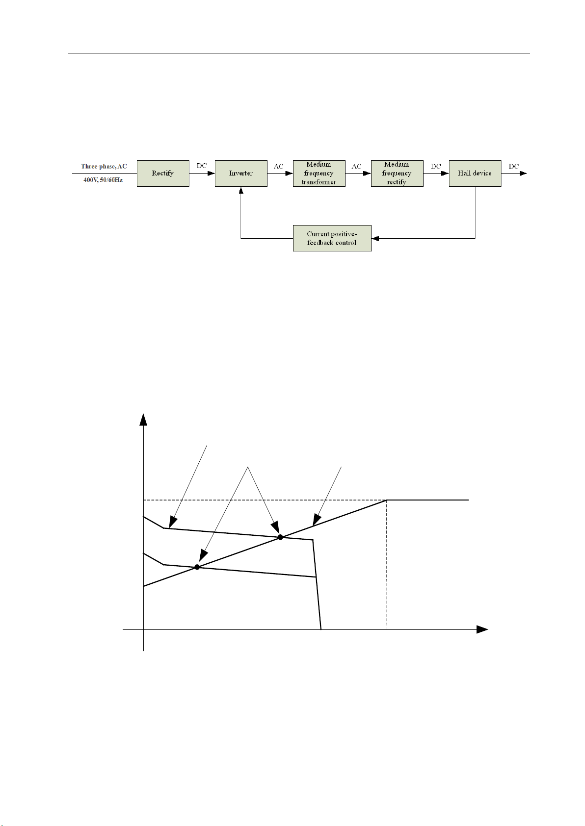
§2.5 Working Principle
The working principle of MULTIMIG F series welding machine is shown as the
following figure. Three-phase 400V work frequency AC is rectified into DC (530V), then
is converted to medium frequency AC (about 20KHz) by inverter device (IGBT), after
reducing voltage by medium transformer (the main transformer) and rectifying by
medium frequency rectifier (fast recovery diodes), and is outputted by inductance
Relation of the welding current and duty
cycle for MULTIMIG 400F SYN
OVERVIEW
12
filtering. The circuit adopts current feedback control technology to insure current output
stably when MMA or TIG. And adopts voltage feedback control technology to insure
voltage output stably when MIG. Meanwhile, the welding current parameter can be
adjusted continuously and infinitely to meet with the requirements of welding craft.
§2.6 Volt-Ampere Characteristic
MULTIMIG F series of welding machines has an excellent volt-ampere characteristic,
whose graph is shown as the following figure. The relation between the rated loading
voltage U2and welding current I2is as follows: U2=14+0.05I2(V).
44
14
0600 I
o
(A)
U
o
(V)
Working point
Volt-ampere characteristic The relation between the rated loading
voltage and welding current

PANEL FUNCTIONS & DESCRIPTIONS
13
§3 Panel Functions & Descriptions
§3.1 Machine Layout Description
§3.1.1 Front and rear panel layout of welding machine
1. On/Off switch: Turn on power supply clockwise and turn off power supply
counterclockwise.
2. Negative Output: When MIG mode, this polarity must connect the work piece.
3. Gas outlet: Connect the inlet of TIG gun.
4. TIG gun control connector.
5. Positive Output: When TIG mode, this polarity must connect the work piece.
6. Gas Inlet: Connect the gas conduit.
7. Output anode: Used to connect to the welding cable of wire feeder.
8. Water box connector: To connect water box.
9. Aviation plug: Used to connect to the control cable of wire feeder.
10. Power source input: To connect power source.
PANEL FUNCTIONS & DESCRIPTIONS
14
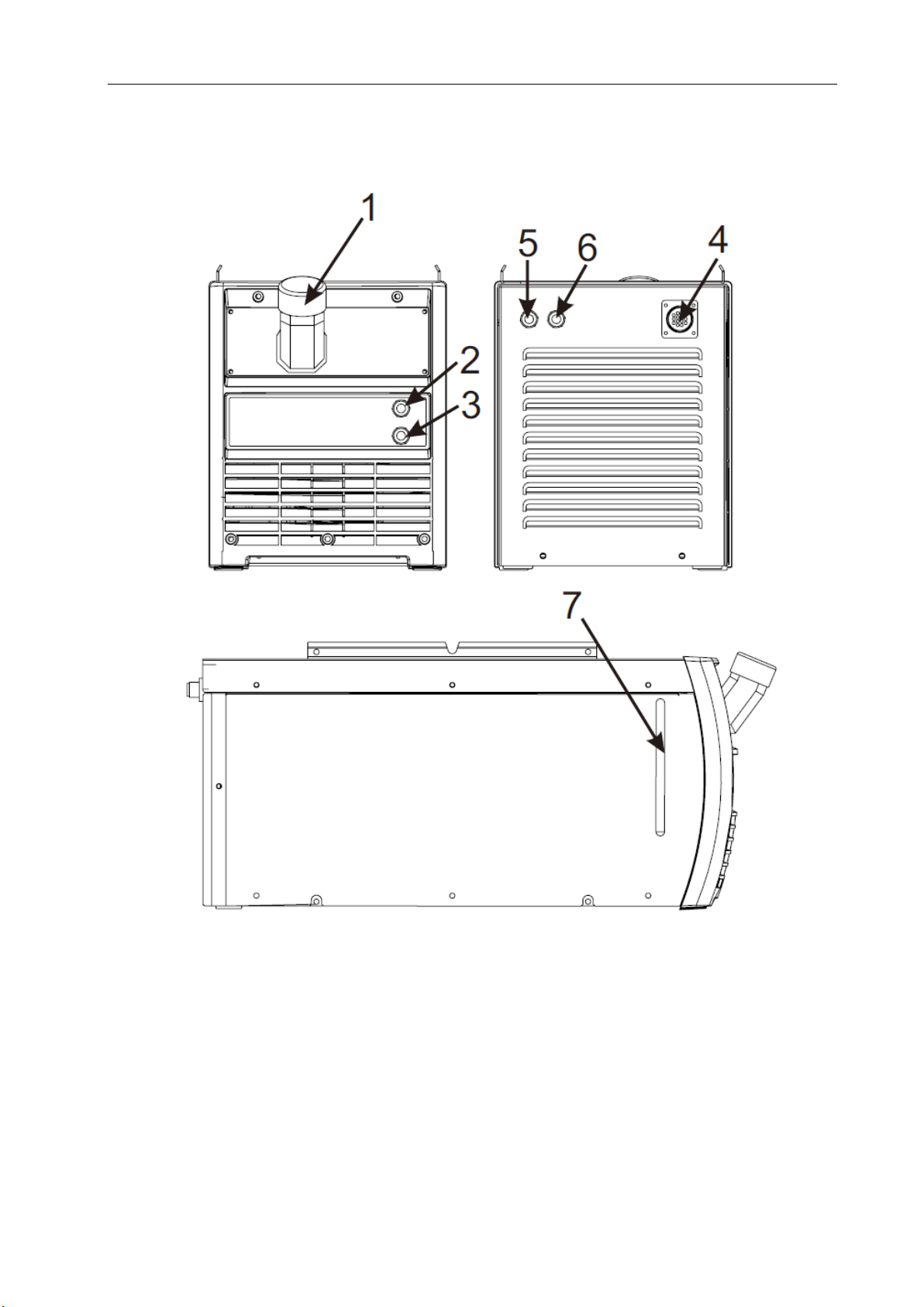
§3.1.2 Front and rear panel layout of water cooling
1. Water inlet: From here, water or coolant, antifreeze, etc. can be injected into tank.
2. Water outlet for TIG (blue).
3. Backwater inlet for TIG (red).
4. The water cooling control connector.
5. Water outlet for MIG (blue).
6. Backwater inlet for MIG (red).
7. Water level calibration.
PANEL FUNCTIONS & DESCRIPTIONS
15
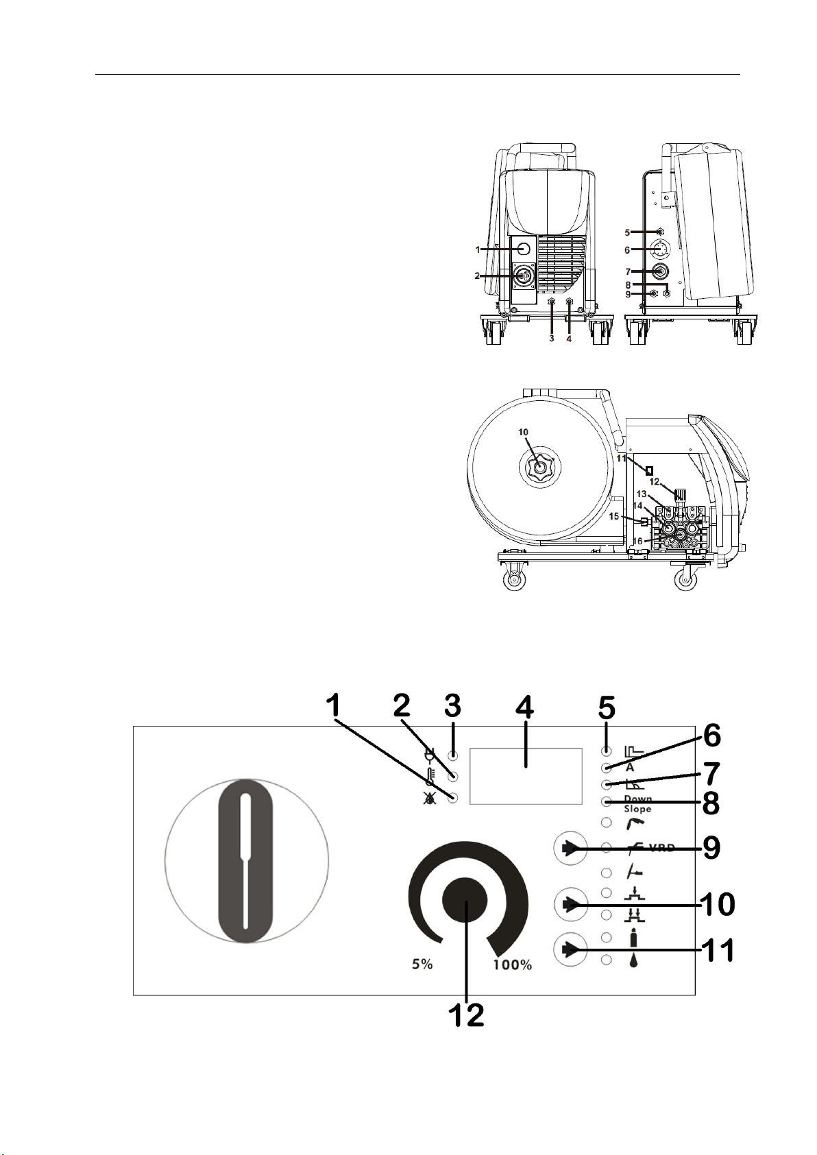
§3.1.3 Wire feeder
1. Spool Gun Power Supply Connection.
2. Mig Torch/Spool Gun connector.
3. Water outlet.
4. Backwater inlet.
5. Gas Inlet connector.
6. The wire feeder control connector.
7. “+” input terminal.
8. Backwater outlet.
9. Water inlet.
10. Spool holder assembly.
11. Spool gun button.
12. Wire feed tension adjustment.
13. Wire feed tension arm (2x).
14. Wire feed roller (2x).
15. Wire feeder inlet guide.
16. Wire drive roller.
§3.2 Front Panel Functions and Descriptions
§3.2.1 Front Panel Functions of welder
1. No water indicator: when the water cooling selected and no water flow, it light on.

PANEL FUNCTIONS & DESCRIPTIONS
16
2. Alarm indicator: When the abnormal conditions such as over-voltage, over-current,
over-heat occur, it light on.
3. Power indicator: When machine is powered on, it light on.
4. Digital display screen: Display voltage and current or other parameters.*
5. Hot Start indicator: When you adjust Hot Start, it light on.
6. Welding current indicator: When the welding current LED is on, it displays the
actual output welding current.
7. Arc Force indicator: When you adjust Arc Force, it light on.
8. Down Slope indicator: When you adjust Down Slope, it light on. Range: 0-10.0.
9. Welding mode key: Press it to select MIG/ MMA VRD /TIG welding mode.*
10. Trigger mode selecting key: Press it to select 2T or 4T mode.*
11. Cooling mode key: Press it to select water cooling or air cooling.
12. Parameter knob: Press down it to select parameters and rotate it to adjust
parameters.
*Denotes more detailed explanation of function to follow.
Further Controls Explained
Digital display screen (4)
When using MIG or spool gun mode, it will display the set voltage value or welding
voltage value; when choosing other mode, it will display the set current value or welding
current value; when choosing or calling parameters, it will display the selected
parameters and their value.
Welding mode key (9)
Four welding modes can be selected here: MIG, MMA VRD, and TIG.
MIG welding mode:
Metal inert-gas welding. Melting electrodes are used to protect metal droplets, weld
pools and high temperature metals in weld pools and high temperature metals in weld
zone with external gas as arc medium.
MMA welding mode:
MMA is an arc welding method using manual electrode. The high temperature
produced by burning between the end of the electrode and the workpiece melts the
electrode, and the melted electrode transits to the surface of the workpiece through the
arc column. Welding rod can not only provide filler metal, but also produce slag skin to

PANEL FUNCTIONS & DESCRIPTIONS
17
protect molten pool without auxiliary gas protection.
VRD welding mode:
VRD mode is designed for human safety. It can reduce the output voltage of no-load
and effectively prevent the danger of electric shock.
TIG welding mode:
Tungsten inert gas welding. Inert gas shielded arc welding using pure tungsten or
activated tungsten as non-melting electrodes, using the arc between tungsten pole and
workpiece as heat source to melt the added welding wire, thus forming the weld. The
tungsten pole does not melt in the welding process and only acts as the electrode. At the
same time, argon or helium is fed into the nozzle of the torch for protection.
Trigger mode selecting key (10)
2T Mode
The trigger is pulled and held on to activate the welding circuit, when the trigger is
released, the welding circuit stops.
This function without the adjustment of start current and crater current is suitable for the
Re-tack welding, transient welding, thin plate welding and so on.
Introduction:
(1) 0: Press the gun switch and hold it. Electromagnetic gas valve is turned on. The
shielding gas stars to flow.
(2) 0~t1: Pre-gas time (0.1~2.0s).
(3) t1~t2: Arc is ignited and the output current rises to the setting welding current (Iwor Ib)
from the min welding current.
(4) t2~t3: During the whole welding process, the gun switch is pressed and held without
Table of contents
Popular Welding System manuals by other brands

Lincoln Global
Lincoln Global BIG RED 600 Operator's manual

Lincoln Electric
Lincoln Electric RANGER 3 PHASE 11079 Operator's manual

SincoSald
SincoSald NOVATIG 203 DC instruction manual

ESAB
ESAB A6 Slide manual

Lincoln Electric
Lincoln Electric Wire Feed Module 12207 Operator's manual

Lincoln Electric
Lincoln Electric SA-400I Operator's manual

ESAB
ESAB PT-31XL instruction manual

Gude
Gude GIS 140 Translation of the original instructions

Lincoln Electric
Lincoln Electric Vantage 300 Operator's manual

Parkside
Parkside PFDS 33 B3 Assembly, operating and safety instructions

HTP
HTP Invertig 301 manual

Alfa Network
Alfa Network PEGAS 160 T PULSE HF Service manual


