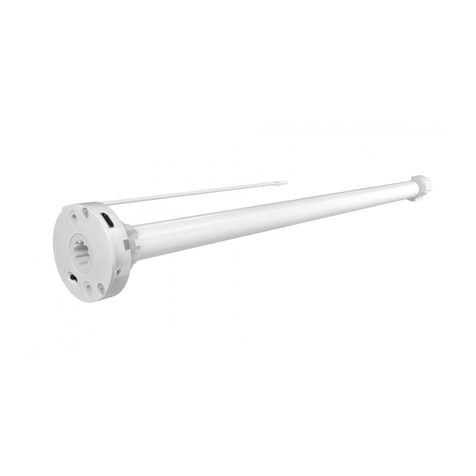
Crestron Electronics CSM-QMTDC Series User manual

The CSM(I)-QMTDC-163 series, CSM(I)-QMTDC-250 series, and CSM
(I)-QMTDC-275 series Crestron® shade motors can be easily removed and
replaced. The CSM(I)-QMTDC series replacement motors are used to
replace an existing shade motor.
In the Box
1 CSM(I)-QMTDCSeries Motor, Replacement Motor
Motor Replacement
CAUTION: Roll up the fabric to prevent damage while replacing the
motor.
NOTES:
lA soft and clean work surface is required to perform this
procedure.
lRemove the fascia and disconnect the motor cable before
performing this procedure.
Remove the Roller Shade Assembly from the
Mounting Brackets
1. Remove the old motor from the motor mounting bracket.
lFor a CSM(I)-QMTDC-163 series motor, press the release button
on the bottom of the shade motor.
lFor a CSM(I)-QMTDC-250 series or CSM(I)-QMTDC-275 series
motor, squeeze the two metal release clips next to the shade
motor.
2. Push the roller shade assembly towards the idler bracket to separate
the motor from the bracket. The idler pin compresses to allow the
motor end to swing out of the bracket.
3. Lift the idler end of the roller shade assembly and remove the idler pin
from the keyhole in the idler bracket.
4. Place the roller shade on a soft, clean surface where it will not be
damaged.
Remove the Old Motor from the Roller Tube
CAUTION: Do not remove the motor by pulling on the control wire.
Remove a CSM(I)-QMTDC-163 or CSM(I)-QMTDC-250
Series Motor
Pull the motor head to remove it from the tube.
NOTES: For CSM(I)-QMTDC-250 series motors:
lRemoving the motor may require a firm, hard pull.
lIf the motor is difficult to remove from the tube, reinstall the
motor latch and use it to help pull the motor from the tube.
1
CSM(I)-QMTDC Series Motor Replacement QuickStart
Replacement Motor

Remove a CSM(I)-QMTDC-275 Series Motor
1. Remove the motor latch from the motor. Save the motor latch for
reassembly.
2. Roll the fabric around the hembar to expose the tube.
3. Reinstall the motor latch.
4. Remove the four screws from the tube.
5. Pull the motor head to remove it from the tube. If the motor is difficult
to remove from the tube, reinstall the motor latch and use it to help
pull the motor from the tube.
Install the New Motor in the Roller Tube
CSM(I)-QMTDC-163 Series or CSM(I)-QMTDC-250 Series
Motors:
1. Fully insert the new motor into the tube. The tube is designed so that
the motor can be easily inserted in only one orientation.
NOTES:
lIf the motor does not easily slide into the tube, rotate the motor
180-degrees and then insert the motor into the tube.
lThe CSM(I)-QMTDC-250 series motors will snap in place. Gently
pull to ensure that the motor is properly secured in the motor
tube.
2. Install the shade assembly according to the mounting bracket’s
installation guide.
CSM(I)-QMTDC-275 Series Motors:
1. Insert the motor into the tube.
2. Ensure that a cusp on the motor crown aligns with the first screw hole
in the roller tube. The cusp should be no further than 1/4 in. (7 mm) off
center of the screw hole. Ensure that the motor head is flush with the
roller tube.
3. Rotate the motor head so that the groove in the motor is shown
through the second screw hole in the roller tube and then use a Phillips
tip screwdriver and two supplied screws to secure the motor head to
the tube. Do not overtighten.
4. Use a Phillips tip screwdriver and two supplied screws to secure the
motor crown to the tube. Do not overtighten.
2
CSM(I)-QMTDC Series Motor Replacement QuickStart
Replacement Motor

Reinstall the Roller Shade Assembly
After the motor has been fully installed, roll the fabric back onto the tube
(if applicable), and then install the shade assembly according to the
mounting bracket’s installation guide.
NOTE: Limits need to be set after installation. Refer to Motor
Programming for details.
Motor Wiring
Routing the Cables
To ensure proper functionality and a clean look, consider the following
when routing cables and making connections:
lThe cables should exit the wall near the motor end of the shade
assembly.
lRoute the cables so that they remain out of sight.
lThe brackets provide a cutout in the upper corner, which allows wiring
to be easily run to the motor.
lA 2-pin connector may be required for shades with a large roll-up
diameter.
lUse cable ties to secure the cables to the loop on the bracket.
lEnsure that the cables and connectors do not make contact with the
shade fabric.
Making the Connections
NOTES:
lWhen making the connections, do not use CRESNET-HP cable with
the small connector. When using CRESNET-HP cable, replace the
connector on the motor pigtail with the larger connector that is
supplied with the shade.
lAll shades should be home run from the power supply (sold
separately).
Cresnet QMT® Shade Motor with the Power and Control Coming from the Same
Source
Cresnet QMT Shade Motor with the Power and Control Coming from Separate
Sources
3
CSM(I)-QMTDC Series Motor Replacement QuickStart
Replacement Motor

Wire the inNET EX® Wireless QMT Shade Motor
Motor Programming
The Crestron® digital CSM(I)-QMTDC shade motors are programmed
locally using the buttons on the motor. The information in this guide
serves as a detailed programming overview of the Crestron CSM
(I)-QMTDC shade motors.
NOTE: The procedures described in this document can also be
performed remotely using a control system. The timeout and LED
indicators are the same as described in this document.
Controls and Indicators
The Crestron CSM(I)-QMTDC shade motors have UP,SET, and DN
(down) push buttons that are used to program the shade. The shade
motors have a multicolor LED that lights red, amber, green, blue, or white
to provide confirmation, operating mode, and error state feedback. The
UP button is located closest to the LED, the SET button is the second
button from the LED, and the DN button is the third button from the
LED.
Crestron CSM-QMTDC Motor Multicolor LED and Push Button Orientation
4
CSM(I)-QMTDC Series Motor Replacement QuickStart
Replacement Motor

Test the Shade
Before the shade is operated, test the motor to ensure that the shade
travels in the correct direction when being operated.
NOTE: Before using the CSM(I)-QMTDC shade motor, ensure the
device is using the latest firmware. Check for the latest firmware for
the CSM(I)-QMTDC shade motor at www.crestron.com/firmware.
Firmware is loaded onto the device using Crestron Toolbox™ software.
Test the Motor Direction
Press the DN button to lower the shade about 1 inch. If the shade travels
up, reverse the motor direction.
NOTE: Reversing the motor direction resets all previously set limits.
After either the upper or lower limit is set, the motor automatically
enters Limit Setup mode for the opposite limit. Follow the procedure in
Set the Shade Limits to reassign limits.
To reverse the shade direction, press and hold the SET button for 10
seconds. The red LED lights for 3 seconds.
Test the Shade Travel
Test the travel of the shade fabric to ensure that it does not come in
contact with building materials and that the upper and lower shade limits
are properly set.
WARNING: Care has been taken to ensure that the shade is properly
balanced. Prior to initial operation, confirm that the brackets are
adjusted so that the shade hangs level and plumb. Upon startup, run
the shade all the way down and check for plumb. Observe the shade
closely as it rolls up. If the shade begins to telescope, stop immediately
and take the appropriate action to ensure the shade tracks properly.
To prevent damage to the fabric from telescoping, do not leave the
shade unattended during the first few cycles of operation. Failure to
follow these instructions may result in damage to the edge of the
fabric, which is not covered by the warranty.
NOTE: For Crestron Horizontal Sheers, the lower limit is defined as the
point before the hem bar tilts.
To test the lower limit:
1. Using the DN button, lower the shade until it reaches its lower limit.
Stop and adjust the mounting brackets if the fabric contacts any
building materials.
2. Verify that the shade stops at the desired lower limit. If the shade does
not travel to the desired lower limit, adjust the shade limits. For details,
refer to Set the Shade Limits.
To test the upper limit:
1. Using the UP button, raise the shade until it reaches its upper limit.
Stop and adjust the mounting brackets if the fabric contacts any
building materials.
2. Verify that the shade stops at the desired upper limit. If the shade does
not travel to the desired upper limit, adjust the shade limits. For
details, refer to Set the Shade Limits.
5
CSM(I)-QMTDC Series Motor Replacement QuickStart
Replacement Motor

Set the Shade Limits
If necessary, set the lower and upper shade limits. If the shade limits are
not set, the red LED flashes three times, pauses for 1 second, flashes
once, pauses for 5 seconds, and then repeats this code until the limits are
set.
NOTES:
lLimit Setup mode exits after 8 seconds of inactivity.
lIf a limit is not set after the upper or lower limit is saved, the motor
automatically enters Limit Setup mode for the opposite limit. This
typically occurs after the motor direction has been reversed and
both limits are erased.
lFor Crestron Horizontal Sheers, the lower limit is defined as the
point before the hem bar tilts.
Set the lower limit for the shade:
1. Press and hold the SET button for 4 seconds to enter Limit Setup
mode. The LED alternates between amber and green.
2. Press and release the DN button to begin lower limit setup. The green
LED flashes.
3. Use the UP and DN buttons to set the shade to its desired position.
4. Press and hold SET for 4 seconds. The LED turns solid red to confirm
that the lower limit was successfully set.
Set the upper limit for the shade:
1. Press and hold SET for 4 seconds to enter Limit Setup mode. The LED
alternates between amber and green.
2. Press and release the UP button to begin upper limit setup. The amber
LED flashes.
3. Use the UP and DN buttons to set the shade to its desired position.
4. Press and hold SET for 4 seconds. The LED turns solid red to confirm
that the upper limit was successfully set.
Joining an infiNET EX® Network (infiNET EX
Interfaces Only)
The device connects to the Crestron network via the infiNET EX
communications protocol. Use the procedures outlined below to join or
leave an infiNET EX network and to verify communications between the
device and the control system.
Joining an infiNET EX Network
Before a device can be used in a lighting system, it must first join an
infiNET EX network by being acquired by an infiNET EX gateway.
NOTE: A device can be acquired by only one gateway.
1. Put the infiNET EX gateway into Acquire mode from the unit itself or
from Crestron Toolbox, as described in its manual at
www.crestron.com/manuals.
NOTE: In an environment where multiple gateways are installed,
only one gateway should be in Acquire mode at any time.
2. Place the device into Acquire mode.
a. Press the SET button three times, and then press and hold it down
(tap-tap-tap-press+hold) until the white LED on the device flashes
once (this can take up to 10 seconds).
b. Release the button to start the acquire process. The LED flashes
slowly to show that the device is actively scanning the infiNET EX
network.
lThe LED turns on for 5 seconds to show that the device has
been successfully acquired to the infiNET EX network.
lThe LED flashes quickly to indicate that the device was not
successfully acquired by the infiNET EX network. Press the SET
button to acknowledge failure to acquire the infiNET EX
network. Ensure the gateway is in Acquire mode and within
range before attempting the acquire process again.
6
CSM(I)-QMTDC Series Motor Replacement QuickStart
Replacement Motor

3. Once all devices have been acquired, take the gateway out of Acquire
mode. Refer to the gateway’s manual for details.
Leaving an infiNET EX Network
To leave an infiNET EX network, put the device into Acquire mode, as
described in Joining an infiNET EX Network when no gateway is in Acquire
mode.
Verifying Communications Status
To check the communications status of the device, tap the SET button
three times and then press and hold it down (tap-tap-tap-press+hold) for
up to 2 seconds. The LED flashes to indicate the communications status.
Refer to the following table for details.
LED CommunicationsStatus
Turns on for 5
seconds
The device is communicating with the control system.
Flashes twice The device was previously joined to the network but is not
communicating with the gateway.
Flashes once The device is not joined to the network.
LED Diagnostics
The LED flashes to provide a visual reference that the motor is operating
normally or if it is in an error state.
Normal Operation
The following table provides a list of possible LED patterns encountered
during normal operation. All LEDs extinguish after 1 minute of inactivity if
there are no errors to report.
LED Patterns
LED Pattern LED
Color Operating Mode
Two fast flashes, then pause
(1/8-second on, 1/8-second off,
1/8-second on, 5/8-second off)
Blue A firmware upgrade over
the Cresnet® network is
in progress.
Slow flash (1/2-second on, 1/2-second
off)
Blue The motor’s internal
firmware upgrade is in
progress.
Solid Blue The motor is in
Bootloader mode.
Fast flash (1/4-second on, 1/4-second
off)
White The motor is in Identify
mode.
Slow flash (1/2-second on, 1/2-second
off)
Green The motor is moving
from a local button
press.
Solid Green The motor is
communicating with the
control system program.
Slow flash (1/2-second on, 1/2-second
off)
Red The motor is not
communicating with the
control system.
7
CSM(I)-QMTDC Series Motor Replacement QuickStart
Replacement Motor

Error State
Crestron CSM(I)-QMTDC motors display error codes using the red LED
on the interface. The LED flashes a pattern to indicate the error.
For example, when a 3-3 LED flash pattern occurs, the LED flashes three
times, pauses for 1 second, flashes three times, pauses for 5 seconds, and
then repeats until the error is corrected. When a 2-1 LED flash pattern
occurs, the LED flashes two times, pauses for 1 second, flashes once,
pauses for 5 seconds, and then repeats this code until the error is
corrected.
The flash patterns are listed in the following table. Refer to
Troubleshooting for possible corrections.
LED Blinking Patterns
LED
ErrorCode Error State
3-1 The motor limits are not set.
3-3 An obstruction is blocking the shade fabric from moving freely.
3-4 A motor over-current error exists. Check for obstacles or any
sources of excessive friction.
3-5 A motor duty-cycle error exists. Reduce the operating duty cycle
of the motor to correct the error.
3-6 There is a communications error between the motor and Cresnet
or infiNET EX control board.
2-1 There is no traffic on the network. Check to ensure that proper
Cresnet wiring is maintained, or for infiNET EX devices, ensure
that the motor is connected to a gateway.
2-2 The motor is not being polled by the control system. Ensure that
the Net ID matches the control system program and that the
program is running on the control system.
Troubleshooting
The following table provides corrective action for possible trouble
situations. If further assistance is required, please contact a Crestron
customer service representative.
Crestron CSM(I)-QMTDC Motor Troubleshooting
Trouble Possible Cause(s) Action
The motor cannot
be controlled, and
all of the LEDs
are off.
There is no power provided
to the motor.
Check the power
connections between the
power supply and motor.
The power connection is
reversed between the
motor and the power
supply.
Ensure that the power
connection to the motor
is not reversed.
The motor moves
in the opposite
direction.
The motor direction is
reversed.
Reverse the direction of
the motor.
The motor
intermittently
stops working.
The motor is exceeding its
maximum duty cycle.
Reduce the duty cycle of
the motor operation.
The motor is encountering
an obstacle or excessive
friction, which is causing it
to stop.
Verify that all
components are aligned
and running smoothly.
The load on the motor is
exceeding its maximum
rating.
Verify that the fabric
weight and tube size do
not exceed the rating for
the motor.
The LED is blue. The motor is stuck in the
bootloader.
Reload firmware to the
motor.
8
CSM(I)-QMTDC Series Motor Replacement QuickStart
Replacement Motor

Additional Information
Original Instructions
The U.S. English version of this document is the original instructions.
All other languages are a translation of the original instructions.
Crestron product development software is licensed to Crestron dealers and Crestron
Service Providers (CSPs) under a limited nonexclusive, nontransferable Software
Development Tools License Agreement. Crestron product operating system software is
licensed to Crestron dealers, CSPs, and end-users under a separate End-User License
Agreement. Both of these Agreements can be found on the Crestron website at
www.crestron.com/legal/software_license_agreement.
The product warranty can be found at www.crestron.com/warranty.
The specific patents that cover Crestron products are listed at
www.crestron.com/legal/patents.
Certain Crestron products contain open source software. For specific information, visit
www.crestron.com/opensource.
Crestron, the Crestron logo, Cresnet, infiNET EX, QMT, and Quiet Motor Technology
are either trademarks or registered trademarks of Crestron Electronics, Inc. in the
United States and/or other countries. Other trademarks, registered trademarks, and
trade names may be used in this document to refer to either the entities claiming the
marks and names or their products. Crestron disclaims any proprietary interest in the
marks and names of others. Crestron is not responsible for errors in typography or
photography.
©2020 Crestron Electronics, Inc.
Doc. 7747D
05/01/20
9
CSM(I)-QMTDC Series Motor Replacement QuickStart
Replacement Motor
This manual suits for next models
7
Table of contents

