crosscontrol CrossLink TG User manual

Product revision: 1.0
2019-03-19
CrossLink TG
Technical Manual
www.crosscontrol.com

CrossLink TG Product revision: 1.0
Technical Manual 2019-03-19
www.crosscontrol.com 2
Contents
Revision history ...............................................................................................................................3
1.Safety and other precautions...................................................................................................4
1.1.General ..................................................................................................................................4
1.2.CrossLink TG connections ....................................................................................................4
1.3.EMC Instructions....................................................................................................................4
1.4.Exposure to RF Energy ..........................................................................................................5
1.5.Antenna care and replacement........................................................................................5
1.6.Electronic devices ................................................................................................................5
1.7.Blasting areas ........................................................................................................................5
1.8.Children..................................................................................................................................5
1.9.Explosive atmospheres.........................................................................................................5
1.10.Handling the device.....................................................................................................6
1.11.CrossLink TG with Battery..............................................................................................6
2.Basic Features............................................................................................................................6
3.Getting Started with the UDK ....................................................................................................7
3.1.Layout ....................................................................................................................................7
3.2.Developer’s Board................................................................................................................8
3.3.Connecting the CrossLink TG Development Kit..............................................................13
3.4.Connecting to a PC ...........................................................................................................13
4.Main Features ..........................................................................................................................14
4.1.Microprocessor and Memory............................................................................................15
4.2.GSM/GPRS System ..............................................................................................................15
4.3.GNSS.....................................................................................................................................15
4.4.Battery Back-Up ..................................................................................................................15
4.5.RTC and GNSS Data Battery..............................................................................................16
4.6.Optional HC Battery ...........................................................................................................16
4.7.USB Interfaces......................................................................................................................16
4.8.Machine Connectors .........................................................................................................16
4.9.Power Supply.......................................................................................................................18
4.10.Digital I/O .....................................................................................................................18
4.11.Analog Inputs...............................................................................................................19
4.12.RS485.............................................................................................................................20
4.13.CAN ..............................................................................................................................20
4.14.Ground .........................................................................................................................20
4.15.Speaker Connection ..................................................................................................20
4.16.Microphone connection............................................................................................21
4.17.SIM Card.......................................................................................................................21
4.18.Antennas ......................................................................................................................21
4.19.LEDs ...............................................................................................................................21
4.20.RJ45...............................................................................................................................22
4.21.uSD Card ......................................................................................................................23
4.22.Internal Temperature ..................................................................................................23

CrossLink TG Product revision: 1.0
Technical Manual 2019-03-19
www.crosscontrol.com 3
4.23.System Time and HW Time .........................................................................................23
4.24.Accelerometer ............................................................................................................23
4.25.Ethernet ........................................................................................................................24
5.Functional States .....................................................................................................................24
6.Firmware...................................................................................................................................25
6.1.Boot Loader.........................................................................................................................25
6.2.Linux Kernel..........................................................................................................................25
6.3.Application Development.................................................................................................26
7.Updating CrossLink TG Firmware............................................................................................27
7.1.uSD........................................................................................................................................27
7.2.TFTP Server............................................................................................................................28
7.3.Creating a Customized UBIFS............................................................................................30
7.4.Creating a Customised UBIFS Image using the current FIrmWare................................30
7.5.Starting the Recovery Image ............................................................................................31
8.U-Boot Environment.................................................................................................................31
8.1.System Boot Protection ......................................................................................................31
9.Systemd - system and service manager...............................................................................32
9.1.Boot Process ........................................................................................................................32
9.2.Unit Files................................................................................................................................33
9.3.System Logging...................................................................................................................33
10.Installation................................................................................................................................34
10.1.Antenna Tuning ...........................................................................................................34
10.2.Antenna Cable Routing .............................................................................................34
10.3.Power Connection......................................................................................................34
10.4.Location .......................................................................................................................35
10.5.Opening the Unit.........................................................................................................35
10.6.Mounting and Fixing the Unit .....................................................................................35
11.Technical Information .............................................................................................................36
11.1.Mechanical Information.............................................................................................36
11.2.Power Interfaces .........................................................................................................37
11.3.GSM/GPRS UMTS/HSPA+ Specifications ...................................................................37
11.4.GNSS Specifications ....................................................................................................37
11.5.Environmental Specifications ....................................................................................38
11.6.Battery Backup ............................................................................................................38
12.References ...............................................................................................................................38
Revision history
Rev Date Author Comments
1.0 2019-04-01 Finn Mc Guirk 0

CrossLink TG Product revision: 1.0
Technical Manual 2019-03-19
www.crosscontrol.com 4
1. Safety and other precautions
1.1. General
IMPORTANT: FOR THE EFFICIENT AND SAFE OPERATION OF YOUR CROSSLINK TG, READ
THE INFORMATION BELOW BEFORE USE.
Care must be taken when handling the unit. It should not be dropped or exposed to excessive heat.
Only authorized staff can disassemble the product. In the case that the product was disassembled
by un-authorized personnel, the warranty will be void.
Do not push foreign objects into the openings of your device. Doing so can cause fire or electric
shock by shorting out interior components.
The product can withstand harsh conditions. But if the product is exposed to severe conditions
beyond the limits specified in Environmental Specifications, the product could be damaged.
Keep the device away from radiators and extreme heat sources. Do not use the CrossLink TG
submerged in wet or very humid environments.
The device may become hot during normal operation, to avoid burns, switch it off and wait for it to
cool before handling it.
Do not clean the device when it is powered. Clean it with a soft cloth. Do not use liquid or aerosol
cleaners, which may contain flammable substances.
1.2. CrossLink TG connections
The highest internal voltage applied to the CrossLink TG unit can be 48Vdc and complies with the
low voltage European directive.
The power supply can be made with a battery or continuous voltage supply with reinforced
isolation, and limited in power to a maximum of 8A and 100VA.
Before you connect the device to a power supply, check the voltage and current rating to ensure that
the required current range matches the available power source. Exceeding the specified input range
may cause unexpected operation and/or irreversible damage to the CrossLink TG.
When you wish to remove the device from all power sources it is advisable to first turn the device
off and then disconnect it from the power supply.
For added safety be sure that nothing rests on the connected cables and that the cables are not
located where they can be tripped over or stepped on.
Applying loads outside of the range specified may result in unintended operation and/or possible
permanent damage to the CrossLink TG. If there is any uncertainty, please visit
https://support.crosscontrol.com/
1.3. EMC Instructions
Use shielded signal cables to ensure that you maintain the appropriate EMC classification for the
intended environment.
Keep cables as short as possible for your application, ideally not longer than 3 meters.

CrossLink TG Product revision: 1.0
Technical Manual 2019-03-19
www.crosscontrol.com 5
1.4. Exposure to RF Energy
Minimize RF energy exposure by limiting the duration of GSM calls and operating the unit in an
efficient manner.
The antenna must be mounted in such a position that no part of the human body rests close to any
part of the antenna. The product is intended to be used with an external GSM antenna, located at
least 20 cm away from any part of the human body. Those installations not complying with this
statement are responsible for providing SAR measurement reports and a corresponding
declaration.
Do not hold the antenna during a call since it affects call quality and may cause the module to
operate at a higher power level than is normally required.
1.5. Antenna care and replacement
Do not use the product with a damaged antenna because an exposed antenna can come into contact
with skin, and a minor burn may result. Therefore, replace the antenna immediately.
Use only antennas that are rated in accordance with the technical specifications. Antennas that do
not fulfil the specifications could damage the product and may contravene local RF emission
regulations or invalidate system approval.
1.6. Electronic devices
Most electronic devices are shielded from RF energy. However RF energy may cause some
malfunctioning of improperly shielded electronic devices.
When the product is mounted in a vehicle, check your vehicle to determine that all on board
electronic equipment is adequately shielded from radio waves.
In the same way, when the product is in the proximity of medical devices (such as in hospitals, etc.)
check with the manufacturer of medical equipment to determine if they are properly shielded.
This equipment should never be operated on an aircraft.
1.7. Blasting areas
To avoid interfering with blasting operations, turn the unit OFF in these situations or in areas
ordered to “turn off your two way radio”.
Similarly construction crew often uses remote control RF devices to set off explosives so proper
care should be taken in proximity to these areas as well.
1.8. Children
Do not allow children to play with CrossLink TG. It is not a toy and they could hurt themselves or
others. Children could also damage the unit.
1.9. Explosive atmospheres
Do not operate this product in environments containing explosive materials or vapour. This
includes petrol vapour at service stations.
The unit accessories could generate sparks that can cause an explosion or fire resulting in bodily
injury or even death.

CrossLink TG Product revision: 1.0
Technical Manual 2019-03-19
www.crosscontrol.com 6
To avoid interfering with blasting operations, turn the unit off in areas posted as such.
Do not transport or store flammable gas, liquid or explosives, in the compartment of your vehicle
which contains the CrossLink TG or its accessories.
1.10. Handling the device
Observe the following safe-handling guidelines to prevent damage to CrossLink TG:
When setting up the device for work, place it on a flat level surface.
Protect the device from environmental hazards such as dirt, dust, food, liquids,
temperature extremes, and overexposure to sunlight.
When you move your device between environments with very different temperature and/or
humidity ranges, condensation may form on or within the device. To avoid damaging it,
allow sufficient time for the moisture to evaporate before using the device.
When taking the device from low-temperature conditions into a warmer environment or
from high-temperature conditions into a cooler environment, allow the device to acclimate
to room temperature before turning on power.
When disconnecting a cable, pull on its connector or on its strain-relief loop, not on the
cable itself. As you pull out the connector, keep it evenly aligned to avoid bending any
connector pins. Also, before you connect a cable make sure both connectors are correctly
oriented and aligned.
1.11. CrossLink TG with Battery
Some models include the optional lithium-ion battery backup. Do not dispose of the battery along
with household waste. Contact your local waste disposal agency for the address of the nearest
battery disposal site.
The battery poses a burn hazard if handled improperly. Do not disassemble or handle a damaged
battery. If the battery is damaged, electrolytes may leak and can cause personal injury.
Keep the battery away from children.
When the battery is heated to excessive temperatures, its cells could explode, posing a risk of fire.
2. Basic Features
The basic features of this product include:
Cortex A8 with 512MB DDR3 and 1GB NAND Flash
Linux Kernel 4.4.19
Debian Filesystem
LinX Software Suite
UMTS/HSPA+: Five Band 800/850/900/1900/2100MHz
GSM/GPRS/EDGE: Quad Band GSM 850/ EGSM900 / GSM1800/ GSM1900.
GNSS Receiver 56-channel with -167dBm tracking and navigation sensitivity
Extensive range of external interfaces (RS-232, digital and analog I/Os…).

CrossLink TG Product revision: 1.0
Technical Manual 2019-03-19
www.crosscontrol.com 7
CAN interface.
Programmable 3 axis accelerometer.
MicroSD card holder.
Please check the datasheet and product variants for the exact features available in your device.
3. Getting Started with the UDK
This section explains the steps to install and configure the UDK development kit to begin the set-up
of the customer applications.
3.1. Layout
The standard unit has GSM and GNSS external antenna connectors, while Bluetooth and Wi-Fi
antennas are internal, as shown in the following image.
When using either Wi-Fi or Bluetooth functionality, try to make sure that the installation exposes
this side of the unit. The “UP” mark shows the side that should be exposeed, and the front should
also not be in direct contact with metallic surfaces.

CrossLink TG Product revision: 1.0
Technical Manual 2019-03-19
www.crosscontrol.com 8
Pin-out for an M12 Connector
M12
RJ45 (Ethernet)
1 TD+ 1TX+
2 RD+ 3RX+
3TD- 2TX-
4RD- 6 RX-
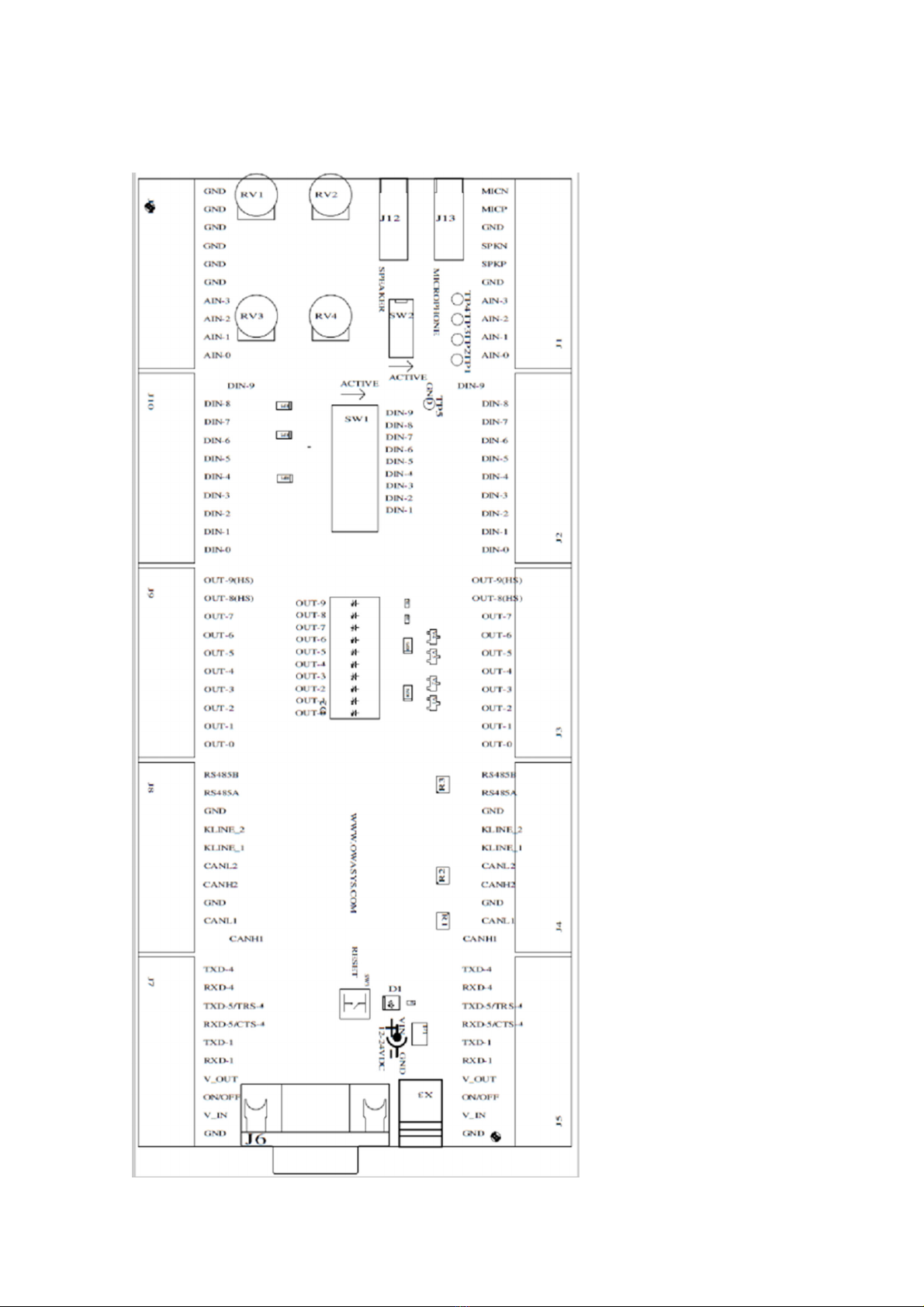
3.2. Developer’s Board
The following figure shows a descriptive and detailed layout of the Development Board and its
associated connectors.
CrossLink TG Product revision: 1.0
Technical Manual 2019-03-19
www.crosscontrol.com 9

CrossLink TG Product revision: 1.0
Technical Manual 2019-03-19
www.crosscontrol.com 10
Number Connector
J1 Connector for audio and analog inputs from CrossLink TG
J2 Connector for digital inputs from CrossLink TG
J3 Connector for digital outputs from CrossLink TG

CrossLink TG Product revision: 1.0
Technical Manual 2019-03-19
www.crosscontrol.com 11
J4 Connector for CAN KLINE and RS485 from CrossLink TG
J5 Connector for power, and RS232 interfaces from CrossLink TG
X3 Jack for DC power supply, 12V or 24V.
J6 DB9 for main uart, UART4
J7 Connector for external devices
J8 Connector for external devices
J9 Connector for external devices
J10 Connector for external devices
J11 Connector for external devices
J12 Jack speaker
J13 Jack microphone
Power may be connected to either X3 or J7. The power input range is 7V – 48V, a fuse F1 is
internally mounted to help prevent damage to other components in case of over-voltage.
Connectors J1 to J5 connections for required signals must be connected to the CrossLink TG. All
the signals are available in the connectors mounted in the front in the case that they have to be
connected to additional external devices.
In order to test the analog inputs, potentiometers are provided. The switch may select the
potentiometer or leave the signal open for an external signal source to be connected.
Digital inputs have switches to change the default status, in order to test the behaviour of all them.
Digital outputs have led indicators, to indicate when they have been activated.
Pin Signal
J1-1 MICN
J1-2 MICP
J1-3 GND
J1-4 SPKN
J1-5 SPKP
J1-6 GND
J1-7 AIN-3
J1-8 AIN-2
J1-9 AIN-1
Analog inputs are connected to potentiometers through switches. The switches should be in the
OFF position if additional external signal sources are to be applied.
Pin Signal
J2-1 DIN-9
J2-2 DIN-8
J2-3 DIN-7
J2-4 DIN-6
J2-5 DIN-5
J2-6 DIN-4
J2-7 DIN-3
J2-8 DIN-2
J2-9 DIN-1

CrossLink TG Product revision: 1.0
Technical Manual 2019-03-19
www.crosscontrol.com 12
Digital inputs have pull downs in the Development kit and a switch to connect to a high level for
input testing.
Digital input 6 is inverted, so it has a pull up by default, and the switch connects the input to GND.
If external signal sources are to be connected the switches should be set in the OFF state.
Pin Signal
J3-1 OUT-9(HS)
J3-2 OUT-8(HS)
J3-3 OUT-7
J3-4 OUT-6
J3-5 OUT-5
J3-6 OUT-4
J3-7 OUT-3
J3-8 OUT-2
J3-9 OUT-1
J3-10 OUT-0
Digital outputs 0 to 7 are open drain, so they give a low value when active. Digital outputs 8 and 9
are High side so they provide a high value (V_IN) when active. All the signals have LEDs to provide
a visual indication of the status of the output. The LED will be on when the output is activated.
Pin Signal
J4-1 RS485B
J4-2 RS485A
J4-3 GND
J4-4 KLINE_2
J4-5 KLINE_1
J4-6 CANL2
J4-7 CANH2
J4-8 GND
J4-9 CANL1
J4-10 CANH1
Note that to use RS485 or CAN, a 120Ωtermination resistor must be placed at each end of the
network. In the development kit there is a termination resistor of 120 ohms soldered for each bus.
Pin Signal Function
J5-1 TXD-4 TX UART4 (Main uart)
J5-2 RXD-4 RX UART4 (Main uart)
J5-3 TXD-5/RTS-4 TX UART 5
J5-4 RXD-5/CTS-4 RX UART 5
J5-5 TXD-1 TX UART1
J5-6 RXD-1 RX UART1
J5-7 V_OUT +5V voltage output 500mA MAX
J5-8 ON/OFF Connect to ground to power down
J5-9 V_IN Powerinput
J5-10 GND Ground

CrossLink TG Product revision: 1.0
Technical Manual 2019-03-19
www.crosscontrol.com 13
RS232 interface signals of the UART4 go to J6 DB9 connector too.
J7, J8, J9, J10, J11 connectors are directly connected to signals coming from the CrossLink TG
connectors in order to connect external devices or signal sources.
3.3. Connecting the CrossLink TG Development Kit
The steps for mounting the components in the device are as follows:
Antennas: Connect the antennas used for the application, 3G, GNSS etc.
DB9 RS-232 Serial connector: Connect a RS232 connector, or USB to RS232 connetor to the PC to
debug the unit.
Signals: Connect the signals needed to the development kit in the connectors J1 to J5. The
development kit has specific use for each of the signal in each of the connections. DIOs should be
connected to the DIN or DOUT depending on which feature is to be tested.
RJ11 cable:
microSIM card: The microSIM card should be introduced in the SIM card compartment. The SIM
card contacts should be faced upwards. Push the SIM card until hearing a click and then lock it with
the flap.
AC/DC Power supply: Provided AC/DC power supply adaptor can be connected to developers
board, connector X3, and to a suitable AC main outlet. Alternatively a laboratory power supply can
be connected to V_IN and GND at J7 connector.
3.4. Connecting to a PC
3.4.1. Serial Connection
Either Linux OS or Windows OS can be used to connect to the device from a Personal Computer
(PC) through the serial port. The required configuration parameters are the following:
• Bit Rate: 115200 bps
• Data Bits: 8
• Parity: none
• Bit Stop: 1
• Flow Control: None
3.4.2. Windows HyperTerminal
Use Windows HyperTerminal to connect the device to the PC configuring the serial port
parameters to the values indicated in previous section.
Switch on the CrossLink TG. Once the Kernel is loaded in RAM memory and the system is running,
the device waits for the user to enter a valid user name to log in. The default user name is root and
the password is root. There is an additional user, debian and password temppwd.

CrossLink TG Product revision: 1.0
Technical Manual 2019-03-19
www.crosscontrol.com 14
Once logged in, the user is in the CrossLink TG file system which has the directory structure of a
usual Linux distro, in this case Debian Jessie.
To transfer a file from the PC to the CrossLink TG, change to /home directory or to the directory
where the file is to be stored (cd /home or cd /directory_name), type rz command and choose the
Transfer-> Send File… option from the HyperTerminal.
To transfer a file from the device to the PC, change to the directory where the file is, then type sz
command indicating the name of the file (sz file_name) and choose the Transfer -> Receive File…
option of the HyperTerminal. In both cases the file transfer protocol is zmodem.
3.4.3. Linux Minicom
Run the minicom program and configure the serial port parameters to the values indicated in
previous section. Minicom help is showed by typing Ctrl-A Z.
Serial port device files (/dev/ttyS0, /dev/ttyS1…) must have reading and writing permissions for all
users. Log in as root and type chmod a+rw /dev/ttySx in order to change permissions.
Switch on the CrossLink TG and wait until a login prompt appears. Log in as root user with
password root to enter into the device operating system.
To transfer a file from the local PC to the device, change to /home directory (or to the directory
where the file is to be stored), type rz command in CrossLink TG OS, type Control-A S so that the
minicom knows the file that is to be transferred. The file transfer protocol is zmodem.
To transfer a file from the device to the local PC, change to the directory where the file to be
transferred is stored, type sz command indicating the name of the file (sz file_name) and type
Control-A R so that the minicom starts to receive the file. The file transfer protocol is also zmodem.
3.4.4. Ethernet Connections
To communicate with the CrossLink TG using an SSH connection can be stablished too using the
Ethernet interface, if the unit features this option. The system sets the SSH daemon up by default,
and its configuration is:
IP: 192.168.10.1
Port: 22 (default port of SSH)
In order to use this connection, connect to this IP using these credentials:
• user: debian
• password: temppwd
The root user can not login to the system by default for security reasons, and it is nenot
recommended to do so. In order to be able to change any configuration, edit the file
/etc/ssh/sshd_config.
4. Main Features

CrossLink TG Product revision: 1.0
Technical Manual 2019-03-19
www.crosscontrol.com 15
4.1. Microprocessor and Memory
CORTEX A8 at 800MHz clock speed with 512 MB of DDR3 and 1GB of non-volatile NAND FLASH.
These provide, in terms of available user space, 468 MB free RAM and 834 MB free Flash for the
default configuration, with a basic Debian running in the system.
4.2. GSM/GPRS System
The CrossLink TG provides GSM communication (Quad band GSM 850/900+1800/1900 as the
default configuration). Audio calls, data calls and Short Message Service are the features supported
by GSM.
GPRS is a widely deployed value added service of the cellular infrastructure that enables direct
access to public and private data networks (Internet, corporate networks, private networks...).
Using the CrossLink TG GPRS service instead of a simple GSM service significantly reduces traffic
cost since resources are only allocated when data is to be sent/received.
GPRS service is class B and class 12. Four time-slots for the downlink and one for the uplink are
available.
HSPA is also available as option with HSDPA Cat.8 / HSUPA Cat.6 data rates: DL 7.2Mbps and UL
5.7Mbps.
4.3. GNSS
GNSS (Global Navigation Satellite System) includes most of the available regional systems
composed of a constellation of satellites orbiting the Earth, such as GPS, GLONASS, Galileo and
Beidou, transmitting signals that allow the GNSS receivers to determine the receiver position
(longitude, latitude and height) and time (Universal Time Coordinated, UTC).
With the GNSS module included in CrossLink TG, accurate position and time information is
provided for Location Based Applications. The default datum used by the GNSS is WGS-84.
The GNSS can work in 2D navigation (viewing 3 satellites) or 3D navigation (viewing at least 4
satellites). When the GNSS starts up, it gives a valid position as soon as it sees 3 satellites, but it can
only know the altitude once it sees 4 satellites. This is the reason why in the starting process, there
is the possibility of a position jump. This position jump is more likely to happen the greater the
altitude is.
The GNSS outputs the altitude as HAE (“Height Above Ellipsoid”) ( i.e. WGS-84). But since an
ellipsoid cannot model the shape of the earth perfectly, one can see some deviation from the so-
called “Mean Sea Level” altitude. MSL refers to the actual sea level. The difference between these
two altitudes can exceed 100m.
The supported GNSS receiver is Ublox NEO-M8N.
4.4. Battery Back-Up
The CrossLink TG is provided with a small dedicated internal battery for RTC and GNSS data
retention. In addition to this it is possible to install a high capacity battery to allow continuous
operation of the CrossLink TG without external power. Units that have this option fitted in the
factory have the “/b” suffix.

CrossLink TG Product revision: 1.0
Technical Manual 2019-03-19
www.crosscontrol.com 16
4.5. RTC and GNSS Data Battery
This is a small dedicated non-rechargeable battery which is supplied with all CrossLink TG units to
provide backup of the RTC and GNSS data. The RTC will be maintained for 10 years. The GNSS
data is continuously backed-up.
4.6. Optional HC Battery
Optional Li-ion batteries are available for the device. 3350mAh and 13400mAh high capacity
battery back-ups can be installed, which allows continuous operation when the main power is lost.
This enables the CrossLink TG/b to, for example, make a final call before going into low power
mode, or a similar procedure, as defined by the customer application software.
4.7. USB Interfaces
USB connector with mass storage functionality.
Pin Signal Function
1 VBUS +5 V
2 D- Data -
3 D+ Data +
4 GND Ground
Connector Type USB Type A
Mating Connector Male Tyoe A
Location Back Panel
4.8. Machine Connectors
To provide maximum flexibility, a 35 pin TE automotive connector is provided with power input,
several RS232 interfaces, digital and analog I/Os and a CAN bus connection.
123456789101112
V_OUT
(5V)
ON/OF
F AIN2 AIN3 CANH1 CANL1 CAN2H CAN2L RS485A RS485B MICN MICP
1314151617181920212223
GND GNDAIN0 DIO-0
DIO-1 /
AIN1
DIO-2
/CAN3L
DIO-3 /
CAN3H
DIO-4/
CANL4
DIO-5 /
CANH4
DIO-6
(iButton
DIO-
7/KLINE

CrossLink TG Product revision: 1.0
Technical Manual 2019-03-19
www.crosscontrol.com 17
) 2
242526272829303132333435
V_IN
DIO-8
(high
side)
DIO-9
(high
side)
TXD-4 RXD-4 TXD-5 /
RTS-4
RXD-5 /
CTS-4 TXD-1 RXD-1 KLINE1 SPKN SPKP
Pin Signal Type Low Level Max Range
1 V_OUT 5V Power output
2 ON/OFF Input OFF 0V ON Open
3 AIN2 Input 0V 5.12V or 30.72V
4 AIN3 Input 0V 5.12V or 30.72V
5 CANH1 BUS
6 CANL1 BUS
7 CANH2 BUS
8 CANL2 BUS
9 RS485A BUS
10 RS485B BUS
11 MICN AUDIO
12 MICP AUDIO
13 GND POWER
14 GND POWER
15 AIN0 Analog Input 0 5.12V or 30.72V
16 DIO-0 Digital Input 0-6V 9V -50V
DIO-0 Open Drain
Output
0,6V@200mA
17 DIO-1 Digital Input 0-2V 3.3V -50V
DIO-1 Open Drain
Output
0,6V@200mA
AIN1 Input 0 5.12V or 30.72V
18 DIO-2 Digital Input 0-2V 3.3V -50V
DIO-2 Open Drain
Output
0,6V@200mA
CAN3L BUS
19 DIO-3 Digital Input 0-2V 3.3V -50V
DIO-3 Open Drain
Output
0,6V@200mA
CAN3H BUS
20 DIO-4 Digital Input 0-2V 3.3V -50V
DIO-4 Open Drain
Output
0,6V@200mA
CANL4 BUS
21 DIO-5 Digital Input 0-2V 3.3V -50V
DIO-5 Open Drain
Output
0,6V@200mA
CANH4 BUS
22 DIO-6 Digital Input 0-1V 1.6V -50V
Open Drain
Output
0,6V@200mA

CrossLink TG Product revision: 1.0
Technical Manual 2019-03-19
www.crosscontrol.com 18
iButton BUS
23 DIO-7 Digital Input 0-2V 3.3V -50V
Open Drain
Output
0,6V@200mA
KLINE 2 BUS
24 V_IN POWER
25 DIO-8(high side) Digital Input 0-2V 3.3V -50V
DIO-8(high side) High Side
Output 1A
VIN
26 DIO-9(high side) Digital Input 0-2V 3.3V -50V
DIO-9(high side) High Side
Output 1A
VIN
27 TXD-4 RS232
28 RXD-4 RS232
29 TXD-5 RS232
RTS-4 RS232
30 RXD-5 RS232
CTS-4 RS232
31 TXD-1 RS232
32 RXD-1 RS232
33 KLINE1 BUS
34 SPKN AUDIO
35 SPKP AUDIO
4.9. Power Supply
Power supply in pin 24 of the machine connector is used to supply power to CrossLink TG. Signals
used for this purpose are:
Pin Signal Type Low Level Max Range
24 Vin Power in 9v 48.0V
13 GND Ground - -
2 ON/OFF Input OFF= 0-0.5v On = Leave OPEN
Vin and GND should be connected to a clean, stable supply between 9.0 and 48.0 Vdc. A cable with
a current rating of more than 5A should be used.
The power supply can be maintained with a battery or continuous voltage supply with reinforced
isolation, and limited in power to a maximum of 8A and 100 VA.
ON/OFF: Power Control Input signal. Leave open for ON, Connect to ground for OFF. Use an open
collector transistor or switch to ground, but do not drive high. This input will turn the unit ON or
OFF. When running from battery back-up, this signal can only be used to turn the unit OFF. If the
signal is then released and there is no power on Vin, then the unit will remain OFF.
4.10. Digital I/O
The CrossLink TG provides up to 10 configurable digital Input/Outputs, from DIO0 to DIO9.
CrossLink TG Product revision: 1.0
Technical Manual 2019-03-19
www.crosscontrol.com 19
These pins can be configured as inputs or as outputs. Note that if the pin is configured as an output
it cannot be used as an input, and may be damaged if a voltage is applied while it is configured as
an output. Hence it is advisable to ensure that the corresponding output pin is OFF before using it
as an input. See the programming guide for more details.
The digital inputs are not TTL compatible, and they can withstand inputs up to 50V so that sensors
and switches with higher voltages can be used. For example, in an automotive application, a switch
may be connected to the positive supply giving an input of 14V or 28V. The input impedance is
68K.
All inputs are inverted except DIO6, which is ready to take a iButton on it, and the range is also
different when using this pin as input (see connector table).
If the digital output is set to 1 in the software it will be OFF and the transistor will pull the output
pin to ground giving a low level. If it is set to 0 in the software it will be ON and the transistor will
be open. Note that there are no pull-ups on these pins so to obtain a high level when the output is
ON requires an external pull-up to a positive supply.
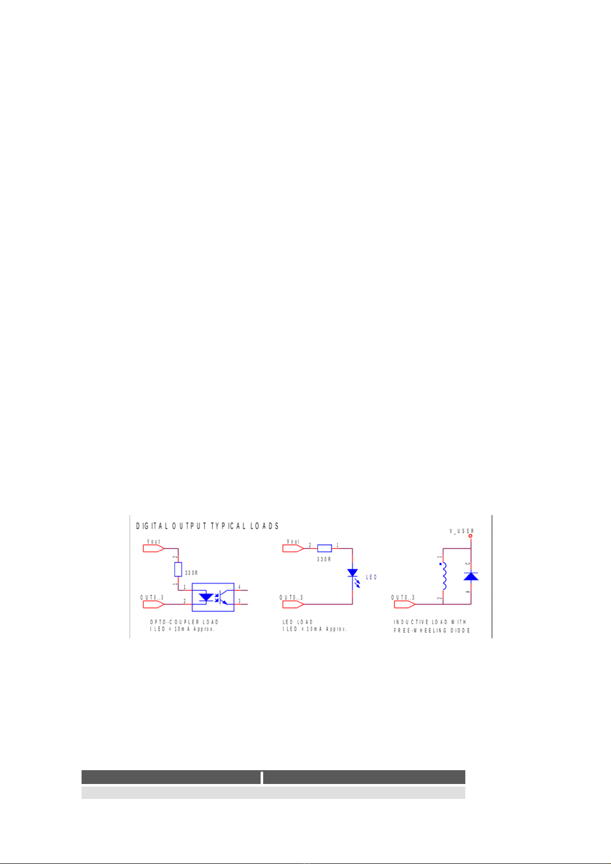
The DIO0to DIO7outputs are open collector transistor type capable of switching up to 50V and
sinking up to 100mA. Do not place a load that will draw more than 200mA or as it may result in
damage to the unit.
With these open collector outputs the load should be connected between the output pin and a
positive supply. The positive supply could be provided by the user, or from the pin Vout (pin 23).
The maximum output current from Vout is 500mA, which should be sufficient to drive up to 8
LEDs, Opto-couplers or Solid State Relays at 10-12mA each. A typical connection for one output is
shown below.
For an inductive load (such as a relay or motor) it is necessary to connect a free-wheeling diode to
provide a return path to the supply for the inductive energy, as shown below. Otherwise the
resulting voltage spikes during switch off could damage the output circuitry.
DIO9 are high side switched digital outputs with Vin as input voltage and with which a maximum
of 1A current can be drawn from them. If loads with higher power are required, the user can
connect them to these outputs. The maximum inductive load is 100 mH.
4.11. Analog Inputs
The 4 analog inputs AIN0 to AIN3 present the following characteristics:
Input Value
Resolution 12 bits

CrossLink TG Product revision: 1.0
Technical Manual 2019-03-19
www.crosscontrol.com 20
Input range 0-5.12V (1.25mV per bit) or 0-30.72V
(7.5mV per bit)
Accuracy ±1% typ. @ 25ºC
Input impedance 68K
4.12. RS485
The CrossLink TG provides an RS485 bus driver.
The 32 devices can be connected in parallel to this interface.
In the following diagram an example of a set of devices connected to the device through a RS485
bus is shown.
The first and last devices in the bus should be equipped with terminating resistors of 120 ohms.
CrossLink TG does not have this terminating resistor internally so it must be added externally as
depicted in this diagram.
4.13. CAN
The CrossLink TG includes two CAN transceivers V2.0B at 1 Mbaud. For more detailed information
see the Programmers and Software Manual.
4.14. Ground
CrossLink TG provides a ground connection for all interfaces, digital I/Os, RS485, CAN and analog
inputs.
4.15. Speaker Connection
Audio output is of BTL type (Bridge Tied Load). That means none of the speaker signals are
internally connected to ground.
Never connect any terminal of the loudspeaker output to ground or power supply as it may damage
either the speaker or the CrossLink TG.
The recommended external loudspeaker has the following features:
• Impedance higher than 3 Ω
• Required power handling: 1.5 W over 8 Ωand 2.5 W over 4 Ω
• Frequency responser between 300 Hz – 3.4 Khz (recommended)
CrossLink TG
CrossLink TG connected using RS485
Other manuals for CrossLink TG
1
Table of contents
Other crosscontrol Industrial Electrical manuals

Popular Industrial Electrical manuals by other brands

BC Northern Lights
BC Northern Lights BloomBox Technical manual

Alpha IP
Alpha IP FSM 26001 instruction manual

Fitel
Fitel S326B operating instructions

Murata
Murata GRT31CR61A476ME13 Series Reference sheet

Murata
Murata GRT155R60J475ME13 Series Reference sheet

Cooper Power Systems
Cooper Power Systems RVE Maintenance instructions

Murata
Murata GRM0335C1H1R5CA01 Series Reference sheet

Siemens
Siemens SIMATIC RTLS operating instructions

Sensorex
Sensorex SD7500CD Product Instruction Sheet

Murata
Murata GQM1555C2DR70WB01 Series Reference sheet

Murata
Murata GRM033C80G104KE19 Series Reference sheet

Murata
Murata GRM033R61A225KE47 Series Reference sheet


