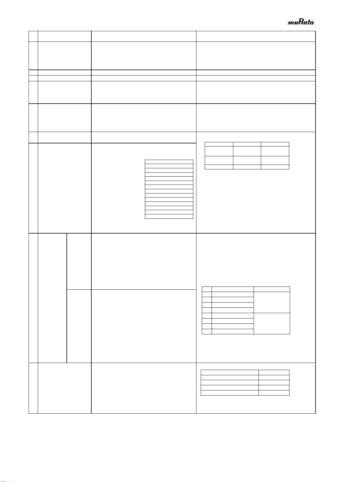
■Specifications and Test Methods (Only for mobile devices)
1 Rated Voltage Shown in Rated value. The rated voltage is defined as the maximum voltage which may be
applied continuously to the capacitor.
When AC voltage is superimposed on DC voltage, VP-P or VO-P,
whichever is larger, should be maintained within the rated voltage
range.
2 Appearance No defects or abnormalities. Visual inspection.
3 Dimension Within the specified dimensions. Using calipers. (GRM02 size is based on Microscope)
4 Voltage proof No defects or abnormalities.
250% of the rated voltage
Charge/discharge current :
5 Insulation Resistance(I.R.)
Measurement Point : Between the terminations
Charge/discharge current :
Measurement Temperature :
6 Capacitance Shown in Rated value.
Measurement Temperature :
7 Dissipation Factor (D.F.) B1,R1,B3,R6,R7,C6,C7,C8,E7,D7 : 0.1 max.
D8,GRM31CR60J107 : 0.15 max
GRM31CR71E106 : 0.125 max
*1 For items listed in Table 1 on the left, the capacitance should
be measured using a voltage of 0.5+/-0.1Vrms instead of
1.0+/-0.2Vrms.
*2 For item GRM188R70J105, the capacitance should be measured
using a voltage of 1.0+/-0.2Vrms instead of 0.5+/-0.1Vrms.
6.Capacitance
Perform a heat treatment at 150+0/-10°C for 1h and then
let sit for 24+/-2h at room temperature,then measure.
8
Temperature No bias B1,B3 : Within +/-10% (-25°C to +85°C) The capacitance change should be measured after 5 min.
Characteristics R1,R7 : Within +/-15% (-55°C to +125°C) at each specified temp. stage.
of Capacitance R6 : Within +/-15% (-55°C to +85°C) In case of applying voltage, the capacitance change should be
C6 : Within +/-22% (-55°C to +85°C) measured after 1 min. with applying voltage in equilibration of
C7 : Within+/-22% (-55°C to +125°C) each temp. stage.
C8 : Within +/-22% (-55°C to +105°C) Capacitance value as a reference is the value in step 3.
E7 : Within +22/-56% (-55°C to +125°C)
D7 : Within +22/-33% (-55°C to +125°C) · Measurement Voltage : 0.20+/-0.03Vrms
D8 : Within +22/-33% (-55°C to +105°C)
50% of B1: Within +10/-30%
the rated R1: Within +15/-40%
・Initial measurement
Perform a heat treatment at 150+0/-10°C for 1h and then
let sit for 24+/-2h at room temperature,then measure.
9 Adhesive Strength No removal of the terminations or other defect Solder the capacitor on the test substrate shown in Fig.3.
of Termination should occur.
Holding Time : 10+/-1s
Applied Direction : In parallel with the test substrate and vertical with the
capacitor side.
Test Method
(Ref. Standard:JIS C 5101, IEC60384)
Type Applied Force(N)
GRM02 1
GRM03 2
GRM15/GRM18 5
GRM21/GRM31/GRM32 10
These Part Numbers are designed for use in the circuits where
continuous applied voltage to the capacitor is derated than rated
voltage, and guarantee Durability Test with 100% × rated voltage
as testing voltage at the maximumoperating temperature.
The voltage and temperature derating conditions on the left are
recommended for use to ensure the same reliability level as
These MLCC products are designed for use in devices with a typicallifetime of less than 5 years.
(Examples: Cellular phone, Smartphone, Tablet PC, Digitalcamera, Watch, Electronics dictionary,
Small-scale server, IPC-9592Bclass1 equipment, etc.)
These MLCC products are designed so that the useful lifetime can be extended longer than 5 years
under the following conditions:
「80% of the rated voltage or less, Maximumoperating temperature -20 degree Cor less」
Extended useful lifetime, under specific operating conditions, can be estimated from
the chart on the left.
※The useful lifetime is the time when cumulative failure rate becomes 1%.
※Please note that the useful lifetime data is for reference only and not guaranteed.
0.1
1
10
100
40 50 60 70 80 90 100 110 120 130
at rated voltage x 80%
85℃Type 105℃Type
50% of
the rated voltage
(For B1,R1)
GRM033 B3/R6 1A 123 to 823
GRM155 B3/R6 1A124 to 105


