Crosslee PLC BG 44A Quick guide
Gas Tumble dryer BG 44A_
2
3
ON/OFF

4

5
Note that gas is not lit when
the
drum
is turning Anti-clockwise.

6
SERVICE INSTRUCTIONS
PROGRAMME
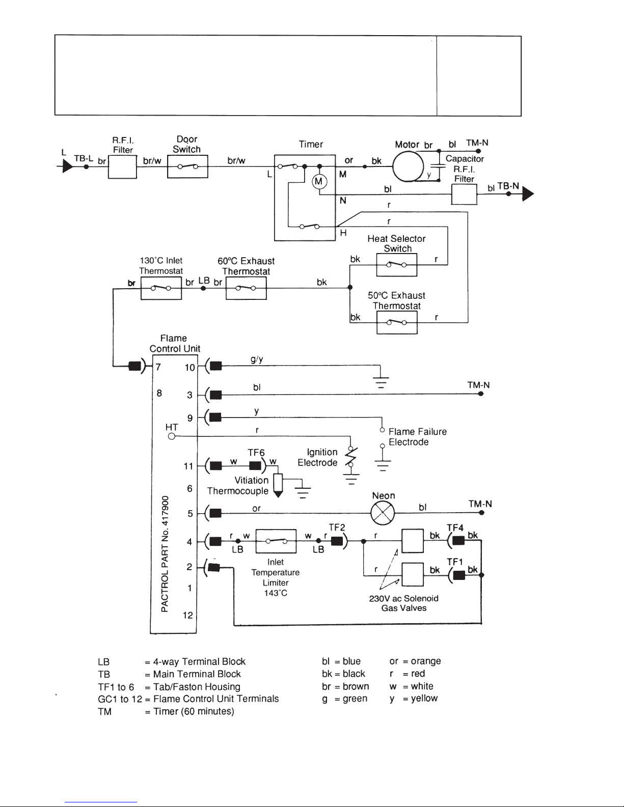
Clockwise rotation of the control knob closes switch
contacts within the timer to: a) energise the drive motor,
and b) energise the full sequence flame controller.
The timer switch controlling the drive motor and the timer
motor, remains closed until the timer motor mechanism
returns the control knob to the ‘O’ position. The timer
switch controlling the full sequence flame controller opens
12 minutes earlier to provide a cool-down period.
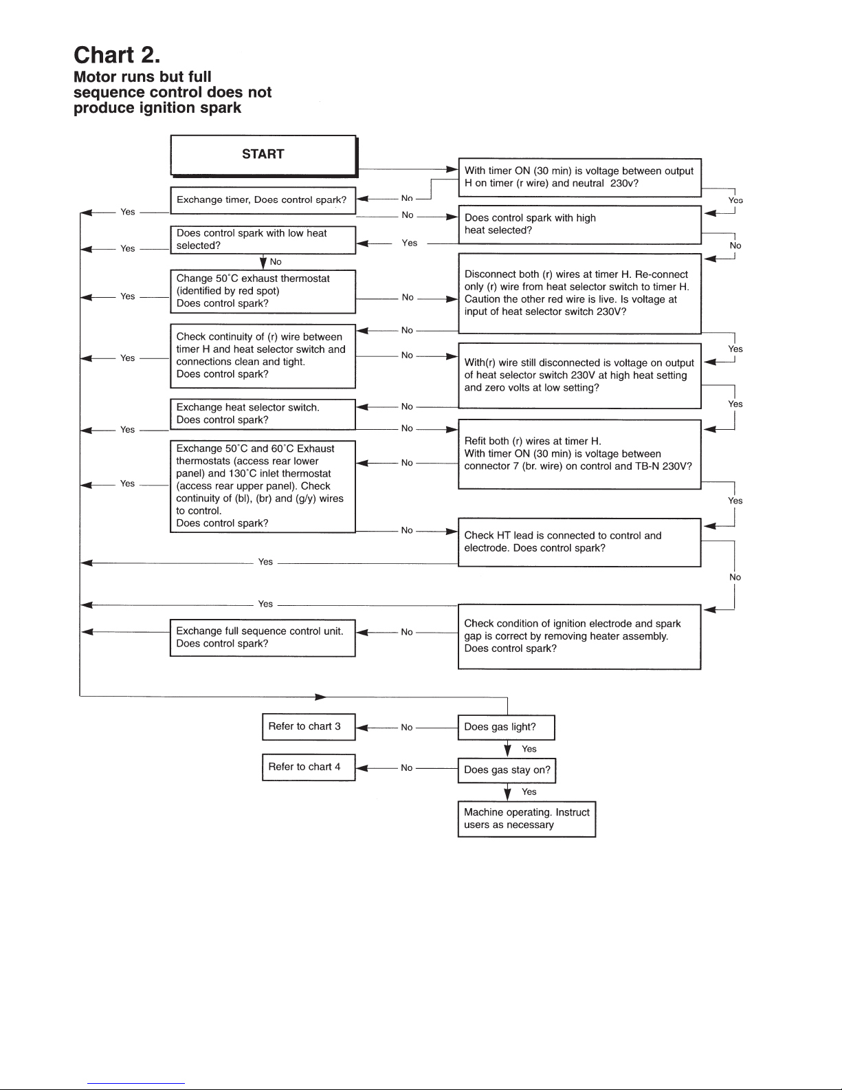
The full sequence flame controller opens the tandem
solenoid gas valves after a delay time of about 8 seconds
and operates the pulsing spark ignition. If the flame is not
detected by the flame failure electrode within 10 seconds
then the valves are closed. The system must then be re-
set by switching the machine off and re-starting.
The heat selector switch provides options for either 60°C,
or 50°C, exhaust thermostat control. This results in the
burner cycling on and off giving longer than anticipated
drying times. Drying times vary depending on the weight
and size of the articles, type of fabric, dampness etc.
These thermostats turn off the heating towards the end of
the cycle and so avoid waste of energy. The lower
temperature thermostat prevents delicate fabrics from
getting too hot with possible risk of damage.
An inlet thermostat is fitted in the ducting at the back of
the dryer. It may operate under certain conditions of
restriction of the air-flow, for example, an overloaded drum
or blocked lint filter. This thermostat switches off the
Flame Controller. This will result in the burner cycling on
and off giving longer than anticipated drying times. Drying
times vary depending on the weight and size of the
articles, type of fabric, dampness etc. Should the
thermostat fail there is an inlet cut-out connected in circuit
with the gas valves. After operation, the cut-out must be
re-set to restore heating but a service call may be
required to correct the initial fault.
The conditions of failure of the air flow, blow-back, or of
gas interruption are detected by the flame failure
electrode and the system is shut-down.
Both drum rotation and heater control are switched off
when the door is opened and switched on when the door
is reclosed.
For programme times see chart on dryer control panel.
Note:
Drying times depend on the weight and size of the
articles, the type of fabric, how damp they are and how
dry they are required.
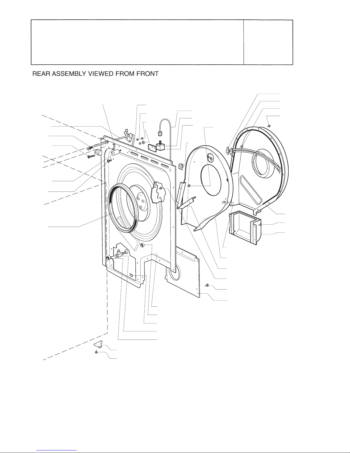
RECOMMENDATIONS FOR DISMANTLING
Note: Re-assembly should be done in reverse
sequence to these instructions.
TOP ACCESS
Terminal Block (28), Control Unit (10), Timer (211),
Heat Switch (235), Neon (213), Micro-Switch
Assembly (248), Control Panel (353).
Withdraw 3 screws from the back flange of the Table Top
Assy. (386) and lift and move it forwards for removal.
This gives access to the 2-screws securing the Control
Unit Bracket (11) to the top flange of the Cabinet.
Pull off the Timer Knob (352) by means of a loop of thin
insulating wire inserted behind it, to expose the 2-screws
securing the Timer (221) to the control Panel (353).
To remove the Neon (213) disconnect the faston
connectors and push the neon out of the Control Panel.
To remove the Control Panel (353), disconnect the faston
connectors from the Timer, Neon, and Heat Switch.
Withdraw 3-screws securing the Control Panel lugs to the
Cabinet top rail. Tilt the Control Panel so that the bottom
lugs can be freed from the top flange of the Front Panel
(376).
To remove the door Micro-Switch Assy. (248), withdraw
the 3-screws securing the Control Panel lugs to the
Cabinet top rail and free the Control Panel Assy. from the
top flange of the Front Panel. Open the door and
withdraw 2 screws securing the Micro-switch Assy, to the
Front Panel, unclip the wires from the top flange of the
Front Panel, lift out the Assy, and disconnect the faston
connectors.
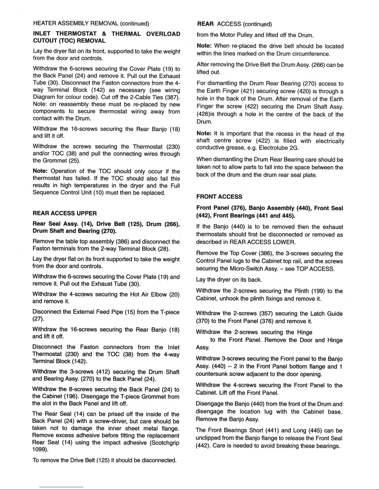
REAR ACCESS LOWER
Exhaust Thermostats (229, 250), Motor Assembly
(101), Fan Assembly (446), Capacitor (112).
Withdraw the 6 screws securing the Cover Plate (19) to
the Back Panel (24) and remove it. Pull out the Exhaust
Tube (30).
This gives access to the Exhaust Thermostats (229, 250),
which are each secured to the Banjo (440) by a screw.
Note: The 50°C thermostat is identified by a red spot on
the face.
7
8
Assembly
(359)

9

10
11

12

13
14
BG 44A_
CROSSLEE P.L.C.

15
BG 44A_
CROSSLEE P.L.C.
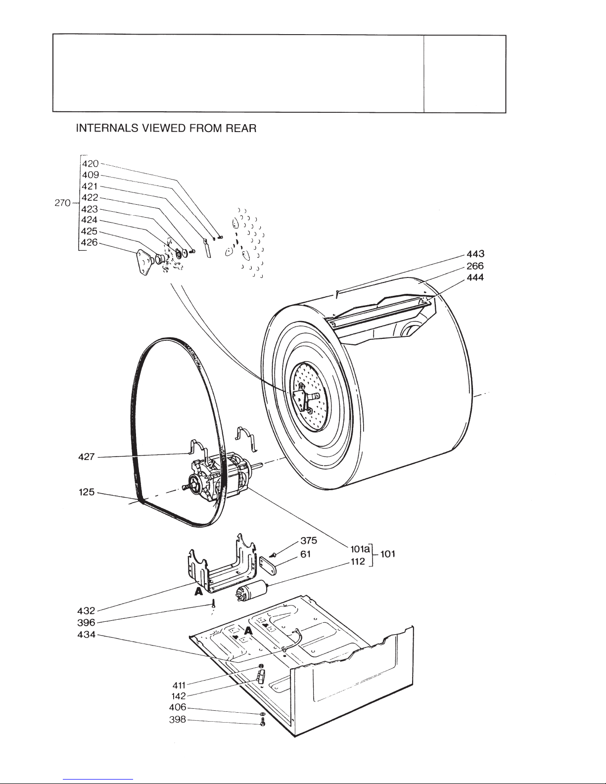
EXPLODED VIEW 1
16
15
16
17
393
375
230
38
389
375
18
375
20
23
21
22
412
375
19
403
396
24
25
26
27
25
14
13
143
398
28
141
408
409
410
411
144
BG 44A_
CROSSLEE P.L.C.
EXPLODED VIEW 2
17
BG 44A_
CROSSLEE P.L.C.
EXPLODED VIEW 3

18
BG 44A_
CROSSLEE P.L.C.
EXPLODED VIEW 4

19
BG 44A_
CROSSLEE P.L.C.
EXPLODED VIEW 5
BG 44A_ Installation/Service Book 4213 094 67121
Manufactured by: Crosslee plc. Lightcliffe Factory, Hipperholme, Halifax, West Yorkshire HX3 8DE.
BG44A_ Parts List
Item Description Part Number Expl. View
10 Control Unit 4213 092 19541 1
11 Control Unit Bracket Assembly 4213 070 08623 1
12 Screw M4 x 20 8213 130 27691 1
13 Screw M4 x 10 8213 130 37161 2, 4 & 5
14 Rear Seal Assembly 4213 092 08511 2
15 External Feed Pipe 4213 089 07883 2
16 Gas Inlet Connector 4213 078 49504 2
17 Restrainer Plate 4213 070 08741 2
18 Rear Banjo 4213 070 08361 2
19 Cover Plate (access) 4213 070 08603 2
20 Hot Air Elbow Assembly 4213 089 09241 2
21 Air Channel/Insulating Plate Assembly 4213 089 07901 2
22 Air Guide 4213 070 08551 2
23 Cable Clip 4213 078 26231 2
24 Back Panel Assembly 4213 089 09232 2
25 Grommet 4213 077 08092 2
26 Captive Nut No 6 'U' Type 8213 130 26301 2
27 Tee Piece/Test Nipple/Plug Assembly 4213 092 08461 2
28 Terminal Block - 2 Way 4213 078 44621 2
29 Exhaust Elbow Assembly 4213 092 08521 5
30 Exhaust Tube 4213 077 48013 5
31 4 Way Housing Assembly 4213 092 08431 4 & 5
32 Burner Assembly 4213 092 09391 5
33 Flame Failure Electrode 4213 092 19801 4
34 Flame Tube Assembly 4213 089 07842 4
37 Test Nipple Plug 4213 078 49422 4
38 Inlet Temperature Limiter 143 Deg C 4213 092 24151 2
39 Ignition Electrode 4213 092 17581 4
41 M4 x 10 Pan Screw 2522 178 08082 4
45 Solenoid Coil (SCEM) 4213 092 08501 4
45a Not applicable for this machine n/a 4
52 Circlip n/a 4
53 Spring Coil n/a 4
57 Thermocouple Assembly 4213 092 09411 5
61 Capacitor Bracket 4213 070 09323 3
101 Motor and Capacitor Assembly 4213 092 35871 3
101a Motor Large 220/240v 50Hz n/a 3
112 Capacitor 8uf 4213 092 08091 3
125 Drive Belt 4213 092 19501 3
141 Mains Cable 4213 076 35122 2
142 Terminal Block 4213 078 44613 3
143 Interference Filter 4213 078 52551 2
196 Cabinet Assembly 4213 092 17761 1
199 Plinth Assembly 4213 089 12651 1
201 Door Seal 4213 077 08341 1
203 Door Frame Assembly 4213 092 21781 1
211 Timer 4213 078 50771 1
213 Neon Assembly 4213 092 09901 1
229 Exhaust Thermostat 60 Deg C 4213 078 53001 5
230 Inlet Thermostat 130 Deg C 4213 092 24161 2
235 Rold Switch (E1026) 4213 078 52401 1
248 Door Microswitch Assembly 4213 092 05251 5
250 Exhaust Thermostat 50 Deg C 4213 078 49453 5
266 Drum Assembly 4213 092 08451 3
270 Drum Shaft/Bearing Kit 4213 092 05591 3
352 Timer Knob Assembly 4213 092 42701 1
353 Control Panel Assembly 4213 092 45321 1
354 Cable Clip 4213 078 26231 1
355 Door Handle 4213 077 61623 1
356 Pan/W Screw St Zn 6 x 7/16 2513 139 03011 1 & 5
357 No 8 x 1 Fl Head S/Tap Screw MC 8213 130 28241 1
359 Door Hinge Assembly 4213 092 25361 1
362 Window 4213 077 44093 1
Item Description Part Number Expl. View
363 Door Frame 4213 077 62303 1
364 Latch Pivot 4213 075 13013 1
365 Latch Spring 4213 075 70833 1
366 Door Latch 4213 077 53413 1
367 Switch Strike 4213 077 53432 1
369 Loom Clip 4213 075 70941 1
370 Latch Guide 4213 077 40992 1
374 Pan Screw St M3 x 10 2522 178 25061 1
375 6 x 3/8 Earth Screw MZP 8213 130 28131 1, 2 & 4
376 Front Panel Assembly 4213 092 18271 1
386 Table Top Assembly - Ellipse 4213 092 42721 1
387 Cable Tie 4213 077 41772 1
389 Screw 6AB x 6.5 2522 163 80023 2
391 Centre Button - Ellipse 4213 077 89001 1
393 Flex Support Clip 4213 077 40982 1 & 2
394 Foot 4213 077 39832 1
396 Flb Ear Scr St Zn 8 x 3/8 2513 200 06166 1, 2 & 3
397 Inlet Filter 4213 081 09192 1
398 Screw M4 x 25 2522 178 25087 2 & 3
403 Roller Assembly 4213 089 00621 2
405 Screw M5 x 16 Hex 4213 078 25872 2
406 M5 Toothed Lockwasher 2522 616 15042 2, 3 & 5
407 Hex Nut DC St Zn M5 2522 401 55012 1 & 2
408 Cable Clamp 4213 077 47303 2
409 Washer M5 Form A 2522 600 65029 2
409 M5 Form A Washer 2522 600 65029 3
410 Fln Tap Scr St Zn 6 x 5/8 2513 154 0602 2
411 M4 Hex Nut 2522 401 55011 2, 3 & 4
412 Screw No 10-24 UNC x 3/8" 8213 130 31051 2
420 Incorporated in 270 3
421 Incorporated in 270 3
422 Incorporated in 270 3
423 Incorporated in 270 3
424 Incorporated in 270 3
425 Incorporated in 270 3
426 Incorporated in 270 3
427 Motor Retaining Clips 4213 078 45361 3
432 Motor Mounting Bracket 4213 070 06756 3
434 Loom Strap 4213 078 46311 3
435 M8 Shakeproof Washer 8213 130 28961 3
436 M8 Hex Nut 8213 130 30651 3
440 Banjo Assembly 4213 092 09441 5
441 Front Bearing (short) 4213 077 40952 5
442 Front Seal 4213 077 61701 5
443 8 x 5/8 Recessed Pan Head Screw 8213 130 28641 3
444 Lifter 4213 077 41009 3
445 Front Bearing (long) 4213 077 40962 5
446 Fan 4213 092 18901 5
447 Access Cover (fan) n/a 5
447/1 Access Cover Assembly 4213 092 18081 5
451 Fln Tap Scr St Zn 8 x 1/2 2513 152 02001 1
454 Filter 4213 092 17821 5
455 Screw 6 x 1/2 2522 164 26009 5
456 Banjo Seal 4213 077 07991 5
458 Banjo Insert No 2 4213 077 53502 5
459 Banjo Insert No 1 4213 077 53492 5
482 M4 Toothed Lockwasher 2522 616 15007 4
537 W' Button (access cover) 4213 078 26311 5
555 Rear Panels Seal Kit 4213 092 28001 2
Bearing Pads & Brush Seal Kit 4213 092 21171
Loom Assembly 4213 076 54892
User Instruction Booklet 4213 094 56167
Table of contents
Other Crosslee PLC Dryer manuals


