Crow PowerWave-16 Operating instructions

P/N 7121240 Rev.B N.A10 December 2003
ELECTRONIC ENGINEERINGLTD
.
PowerWave-16
16 zoneControlpanel Communicator
Users’ Operating and
ProgrammingGuide
Version6.31 / 6.32
CoversVersions6.20and Above

2
Contents
Introduction.....................................................................................................4
Meet the Crow AlarmControl System.........................................................4
Typical AlarmSystemConfiguration...........................................................4
Keypad Description..........................................................................................5
Function Keys..................................................................................................5
AlphanumericKeys.........................................................................................5
Audible Signals...............................................................................................6
Indicators........................................................................................................6
Zone and StatusindicatorsLEDs1-16......................................................6
PartitionsindicatorsLEDsA,B ,C.............................................................6
Armed indicator,Memory indicator,Bypassindicator........................6
Programindicator,Auxindicator,Mainsindicator..................................6
Tamperindicator,Batteryindicator,Lineindicator,Control
indicator..........................................................................................................6
Summary of Functions...................................................................................6
Operation..........................................................................................................8
How to Armthe Systembefore Exit..........................................................8
How to Armthe Systemwhen Staying Home.............................................9
How to ArmPartitions...................................................................................9
How to BypassZones....................................................................................10
How to use Chime (If enable by Installer)...............................................11
Emergency Alerts..........................................................................................10
Generate Threat orDuress.........................................................................11
How to Read SystemMessages...................................................................11
How to Read Trouble Messages...................................................................12

3
How to DisplayEventsfromMemory..........................................................12
How to Control Outputsand Devices..........................................................14
How to Get into to UserProgram/Client Mode.........................................14
How to Change orAdd Codes.......................................................................15
How to Change MasterCode........................................................................15
How to Add orChange UserCode...............................................................15
How to Delete UserCode.............................................................................16
How to Add orChange Telephone Numbers...............................................16
How to set Time and Date............................................................................16
How to operate the access control output.................................................17
How to start Walktest Mode......................................................................17
Warranty.......................................................................................................20

4
Introduction
Meet the CrowAlarmControl System
Thankyou forchoosingtoprotectyourpremiseswith aPowerWave-16 (PW16) of Crow
ElectronicEngineeringLtd.
PowerWaveofCrowElectronicEngineering Ltd.isahighlyadvanced, multifunction
alarm control system,designed toflawlesslymanageyoursecuritysystemat homeorat
business,protects you against burglaryand supportstheoperation ofelectronic devices.
The PW16 hasmanyincredibleprogramoptionsandadditionalaccessoriesthatcan
enhancethestandard featuresof thepanel fromsimple“HomeAutomation” to“Wireless
control” and VoicePrompted Telephonecontrol”. Pleaseaskyourinstaller tofindout
moreabout these powerful features.
You can phoneyour hometocheckorchangethestatus ofanyoutput usingthekeyson
yourphone. Armor disarmthewholehouseorjustonearea, allwith yourown voice
confirmingyour selections.
Imagineturning on thespabeforeleaving worksoit is hotwhen you getinthedoor.The
under-floor heating hasjustautomaticallyswitched on using theon board timerandyou
havejustopened therollerdoor anddisarmed thegaragefromyourcellphonesothe
whiteware repairman can workon yourwasher.
Thecontroller will support a16LED keypad orthemoresophisticated LCD (liquid
Crystal Display)keypad.
It alsohasacomprehensivealarmeventmemorythat storesallofthecontrolleractivity
withthe timeanddate.
Typical Alarm System Configuration
The protected premisescan bedivided upto16zones,asdefinedbytheinstallation
scheme. Theprotected area can begrouped into3separatepartitions(A,B, C). The
system can begrouped for User ‘s conveniencetoseparate, inabusiness environment,
theofficesfromthewarehousearea, or inaprivateresidence,thedifferent areasin the
home, e.g.,separatedownstairslivingarea,detached garage, etc.Eachzonecan react
differentlytovarious events, togeneratean alarmor activatea device.
The systemcan bearmedintwo differentmodes:
1) Arm –theprotected areas areentirelyvacated
2) Stay –peopleandpetspopulate the protected areas.
The Userwho hasaccess to thekeypad'scontrol features, can changethe settings.
Thesystemcanbeaccessed viamultiplekeypads(eachlocated at adifferentsite). Up
to8keypadscan beintegrated intothesystem.Access levelsand Users’access codes
aredetailed below.

5
KeypadDescription
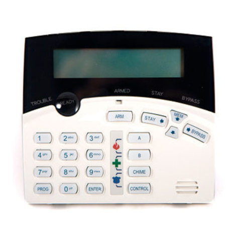
The LEDKeypadshowsalltheinformationrequired tooperatethe system.TheUser
communicateswith thealarmsystemviathekeypad.TheKeypad displayscontinuous
information about thestatusofthealarmsystem,andenablestheUsertooperatethe
systemindifferentmodes, change settings and programUsers'access codes.
Thekeypad alsocollectsandrecordseventstobedisplayed afterward on request, to
overview system activities,andtoanalyze systemperformancefordiagnostics.
Function Keys
Thesekeysareusedtoarmthe system,enter Telephonestoalter systemsettings,or
scroll through the historyevents.
ARM, STAY,BYPASS, PROGRAM, CONTROL, MEMORY, PANIC, ENTER
Alphanumeric Keys
Thesekeysareusedtoenter codes,Initiate Emergencyorforprogramming.

6
Audible Signals
Thekeypademitssignals(beeps)inresponsetoUser activities.Thesesignalsare
listed in Table. Table: List of Audible Signals
Sound Sequence Description
Short beep OnceonlyA keyin thekeypad has beenpressed
3 short beepsOnceonlyOperationcarried out successfully
Long beepOnceonlyIllegal operation,or wrong keypressed
Slowbeeping Through the Exitor
Entrydelaytime Exitor entrydelaywarningwhen arming
the systemindicatesthat you must exitthe
protected area,
alsoEntrydelaywarning when entering
via theentryzone,to disarmthe system.
Indicators
Thereare 30LEDsindicatorsshow thestatus ofthe system.
Zoneand StatusindicatorsLEDs1- 16
Partitions indicators LEDsA, B, C
Armed indicator,Memoryindicator,Bypass indicator
Programindicator, Aux indicator, Mains indicator
Tamper indicator,Battery indicator, Line indicator, Control indicator
Summaryof Functions
The system'smain functions arelisted in table
Function Keys Description Notes
Full
or Partition ArmCC OD E C
ENTER
Initiatesfullarm
Full Arm C
ARM
InitiatesfullarmOnlyif enabledby
installer
Disarmduring
exit C
ARM
Disarmsthe
systemduring
exitdelay
Onlywhenslow beeping
is emitted
Disarm CC OD E C
ENTER
Disarmsthe
system Stopping Alarms

7
Function Keys Description Notes
ArmStay C
STAY
CC OD E
C
ENTER
Initiates partial
alarm whenthe
user is home
Onlyif enabledby
installer
ArmStay C
STAY
Initiates partial
alarm whenthe
user is home
DisarmStay CC OD E C
ENTER
Disarmsthe
system
DisarmStay C
STAY
Disarmsthe
system
Bypass C
BYPASS
C
Zone#
C
ENTER
Bypasses a
zone(s) Repeats theprocedureto
un-bypass zones
InitiatePanic C
PANIC
Activates panic
alert
InitiatePanic C1+ 3Activates
emergencyalert Onlyif enabledby
installer
InitiateMedical
C7+9Activates
emergencyalert Onlyif enabledby
installer
InitiateFire
Alarm C4+6Activates
emergencyalert Onlyif enabledby
installer
Memory CMEMORY Initiates display
of eventsfrom
memory.
<ENTER>
cancels memory
readout
Displays events,and
automaticallyscrollsto
the next event every2.5
sec.
(Use <MEMORY> keyto
scrollup manually)
Chime
Enable/disable CCONTROL CPROGRAM Enableor
disable chime
function
Onlyif enabledby
installer
Control C
CONTROL
CDevice#
C
ENTER
Activates or
deactivates
outputs and
devices
Press <Control> for2
seconds
Changeor Add
Users' code CPROGRAM CMCODE
C
ENTER
Activates
programmode to
addor change
Users' codes
Fordetailssee
page12
Note:Ifyou started anoperationincorrectly,press <ENTER>toexit and
return totheprevious mode.

8
Operation
Howto Arm the System beforeExit
• Preparingthe System for Arming
Verifythatall zoneindicatorsareoff,when allzonesareclosed (all doors,exitsand
windowsareclosed and motion intheprotected area isrestricted orbypassed),the
systemisreadytobearmed. Ifoneor morezoneindicatorsareilluminated,itdisplays
theopen zones.
Closeopen zones, or bypassthem.Bypass anyzoneyou cannot close,<Bypass>
indicator flashesindicatingbypassed zone(s).For detailssee page9.
Note:Bypassed zones are not protected.
• Armingthe System
Beforeleaving premisesthesystemhastobearmed.
Arming thealarmsystem will turnon alldetectors inthepartition /s beingarmed.
Enter user code and then <ENTER>toarmthe system.
Thereisaexitdelayprior tothesystembeingarmed.Duringthisdelaytime, aslow
beepingisheard toindicatethat thesystemisnotarmed yet andremindsyou toleave
the protected area.
The A,Bor Cindicator lights up to indicate that the systemis armed.
(Theindicatorsmaygooutfew secondsafterexit delayexpired, dependingon the
installer'ssetting).
Ifyou mustdisarmthe systemduring theexitdelay,press <ARM>.
• Quick Arm (When enabled bythe installer)
Press <ARM> toarmthe system.
The A,B or C indicator lights up to indicate that the systemis armed.
During exitdelaytime, a slow beepingisheard reminds youtoleavethe protected area.
• Disarmingthe System
Enter User’s code andpress <ENTER>. The A,Bor Cindicatorgoes off toindicatethat
the systemisdisarmed.
• StoppingResettingAlarms
In caseof an alarmcondition
Enter User’scode and press <ENTER>tostop alarmanytime, and turnoff anyaudible
sirens.

9
Howto Arm the System when StayingHome
• Armingthe System in Stay Mode
Thistypeofarmingisusedwhenpeoplearepresentwithinthe protectedarea.At
nighttime,when thefamilyisabout toretire, perimeter zonesareprotected,but not the
interior zones. Consequently,interior movements will be ignored bythesystem.
ToarmStaymodepress <STAY>, enter user code, and then <ENTER>.
The A,Bor Cindicator flashestoindicatethat the systemis armedin staymode.
• Quick Stay
Whenenabled bytheinstaller,press <STAY>toarmthe system.
During exitdelayyou can leavethepremises.Ifyou wishtostayor that noonewill
enter theprotected premises,youmaycancel theEntry/exitdelaybypressingthe
<ENTER>key.Theslow beeping stops and thesystemisimmediatelyarmed.
The A,B or C indicator flashesto indicate that the systemis armed in staymode.
(Theindicatorsmaygooutafewsecondsafter exit delayexpired,dependingon the
installer'ssetting).
• Disarmingthe System
Enter user’s code andpress <ENTER>, or press <STAY>if enabledbyinstaller.
The A,B or C indicatorgoes off to indicate thatthe systemis disarmed.
Howto Arm Partitions
Theprotected area can begrouped into3separatepartitions(A, B,C). Thesystemcan
begrouped forUser‘sconveniencetoseparate, inabusiness environment,theoffices
fromthewarehousearea, or inaprivateresidence, thedifferent areasin thehome, e.g.,
separate downstairsliving area,detached garage, etc.
To arm partitionAenter usercodefor partitionA
To arm partitionBenter usercodefor partitionB
To arm partition C enter usercodefor partition C
Note:toarming partition with code see page8 “How toarmthesystembeforeexit”
During exitdelayyoucanleavepremises.At theendoftheprocedurethe A,B or C
indicator lightsup to indicate that the partition Aor/andB or Cis armed .
(Theindicators maygooutafter a fewseconds, depending on theinstaller'ssetting).
Todisarmpartition,see"Disarmingthe System".

10
Howto Bypass Zones
Bypass anyzonethat cannotbe closed. Youcan bypass selected zonespriortoarming.
It is also used to temporarilyexcludea faultyzone fromservice, which requires repair.
Tobypass aselected zone, press <BYPASS>, Bypass indicator lights up toindicatethat
the systemisin bypass mode.
Enter the zone number (e.g. 01, 05, 12) oneor morezones,thezoneLED indicators
lightsuptoindicatethatthezoneisbypassed,followingpress <ENTER>,theBypass
LED flashesto indicatezone(s) bypassed.
Whilein theBypass modeit ispossibletobypass morethanonezone,press
<BYPASS>,Bypass indicator lights upto indicate thatthesystemisin bypass mode,
Add the zonenumber (e.g. 03) oneor morezones,thezoneLED indicatorslights upto
indicatethat thezoneisbypassed,followingpress <ENTER>,theBypass LEDflashes
toindicatezone(s) bypassed.
Toun-bypass zones, press <BYPASS>,enter zonenumber (e.g.07,13) ,thezoneLED
indicators goes off to indicate that thezone is unbypassed and<ENTER>.
Note:Disarmingautomaticallyun-bypasses all zones.
EmergencyAlerts
Thisthree special key’sfunctionisbest programmed byyourinstaller tosuityour
individual situation.Most commonlyit isused in apanicsituation.
Thesearea“PANIC”,“FIRE”, and“MEDICAL”alarm.When usingtheLED keypadthe
Panicalarmcan begenerated byeither thesingle“Panic”button or bythesimultaneous
operation oftwo buttons.Pressing two buttonssimultaneouslygeneratestheFireand
Medical alarms
• Howto initiatePanic
Press the<PANIC>or Press simultaneously<1>and<3>.
• Howto initiateMedical Alarm
Press simultaneously<7>and<9>.
• Howto initiate Fire Alarm
Press simultaneously<4> and <6>.

11
Howto use Chime(If enable by Installer)
AChime(Dayzone) isadetector thatcanbepartarmed whileyou areathomebut
workingin another part of thebuilding. It canbeprogrammed tooperateabuzzer orlight
tolet youknow youhaveavisitor.
Todisablethe Day(chime)zone,press <CONTROL>and<PROGRAM> ,ControlLED
indicator lights upto indicate thatChimeisdisabled .
ToenableChimemodepress <CONTROL>and<PROGRAM>ControlLED goesoff to
indicate that Chime is active.
Generate Threat or Duress
Ifyouarecompelledtodisarmthesystemunder threat,youmustentertheduress digit
beforetheuser’scodetoactivatetheautomaticdialer.Theduress digitshiftsupyour
usual codebyonedigit. Ifyour codeis345and8isyour duressdigit, than entering
8345 will modifyyour code. Themodified duress codewill disarmthesystemin a
normal way,butat thesametimewillactivatethedialersilentlytoreport a“duress
event” without arousing suspicion. (Fordetails askinstaller.)
Howto Read SystemMessages
Whenviewingthememoryevents at thekeypadbypressing the<MEMORY>,the first
thingthat willalways bedisplayed isthesystemmessages.
Ifthe systemledturnsONbut noother Zone LED’s are ON at the same time, thismeans
that therearenocurrent systemalarms.IfazoneLED andLED’s areON then this
indicatessystemalarmsthathavenot yet cleared. TheLED’s1-8arepre-defined asto
whatsystemalarmtheywill display.Thesesystemalarmindicationsareshowninthe
table below.
Following thedisplayof current systemalarms thepanelwillthen sequencethrough the
255historicalmemoryevents startingat themostrecentevent. Thesecond tableshows
thealarmevents thatcan bedisplayed inmemorymodeandwhat indicatorsareused to
showthem.
LED # 1 BatteryLow LED #5
Wireless Keyfob BatteryLow
LED #2Mains FailureLED #6
Supervised DetectorFailure
LED #3 TelephoneLineFailure LED #7
ZoneInactivityTimeout
LED #4 Wireless DetectorBattery
Low LED #8
DialerKiss-off Failure

12
Howto Read Trouble Messages
Anyfailureor abnormal eventsthatmayoccurareindicated bytroublemessages,and
theTroubleindicator islit.Press <MEMORY>toreadoutmessagesandotherevents
stored inmemory.
Howto DisplayEvents from Memory
The systemmemorystoresthelastevents.Press <MEMORY>todisplaylistofevents.
Following the displayofcurrentsystemalarmsthepanel willthensequencethrough
the 255 historical memoryeventsstartingat themost recentevent. Thesecond table
showsthealarmeventsthat can bedisplayedinmemorymodeandwhatindicatorsare
usedto show them.
The systemwilldisplaythelasteventandautomaticallyscrolltothenextoneevery2.5
seconds, and abeepis emitted. Usethearrow keys toscroll upmanually.
Wait until allmessages are displayed,orpress <ENTER>to cancel memoryreadout.
EVENTTYPE DEVICE INDICATOR STATUS
ACTIVATION Zones1-16 LED's 1-16 On Steady
BYPASS Zones1-16 Bypass
LED's 1-16 On Steady
On Steady
DETECTORTAMPER
(SHORTCIRCUIT) Zones1-8 TAMPER
LED's 1-8 Flashing
On Steady
DETECTORTAMPER
(OPEN CIRCUIT) Zones9-16 TAMPER
LED's 9-16 Flashing
On Steady
WRONGCODEALARM Codeat Keypad # TAMPER
LED's 1-8 On Steady
On Steady
CABINETTAMPER Cabinet or Siren TAMPER Flashing
KEYPADTAMPER SWITCH Tamper alarm at
keypad TAMPER
LED's 1-8 On Steady
On Steady
LOW BATTERY ControllerBattery BATTERY Flashing
MAINSFAILURE ControllerMains
Supply MAINS Flashing
FUSE FAILURE F1or F2 Controller on-board
Fuses
MAINS Flashing

13
WIRELESS ZONELOW
BATTERY Wireless Zone1-16 BATTERY
LED's 1-16 Flashing
On Steady
KEYFOBLOW BATTERY
Wireless Keyfob User
1-20 BATTERY
LED's 1-16 Flashing
On Steady
PANIC BUTTON(or
BUTTONS1&3 PRESSED
TOGETHER)
Keypad Panic
At keypad # LINE
LED's 1-8 Flashing
Flashing
FIRE ALARM(BUTTONS4&6
PRESSED TOGETHER) Keypad Fire
LINE
CONTROL Flashing
Flashing
MEDICAL ALARM(BUTTONS
7&9 PRESSEDTOGETHER)
Keypad Medical LINE
BYPASS Flashing
Flashing
ARMEDA Area A isArmed AREA A On Steady
ARMEDB Area B isArmed AREA B On Steady
ARMEDC Area C is Armed AREA C On Steady
STAYMODEA Area A STAYMode
ON AREA A Flashing
STAYMODEB Area B STAYMode
ON AREA B Flashing
STAYMODE C Area C STAYMode
ON AREA C Flashing
DURESS ALARM Duress Alarm
At keypad #
TAMPER
LINE
LED’s 1-8
Flashing
Flashing
On Steady
SUPERVISEDWIRELESS
ALARM Supervised Wireless
Passive Infra-Red Bypass
TAMPER
LED’s 1-16
Flashing
Flashing
On Steady
ZONE INACTIVITY ALARM Zones1-16 LED’s 1-16
TAMPER
CONTROL
On Steady
Flashing
Flashing
TELEPHONE LINE FAILURE
Phone Line Failure LINE On Steady
EXCESSIVE RE-TRIES PanelDialler LINE
LED1
On Steady
On Steady

14
FAILURETOGET AKISSOFF
PanelDialler LINE
LED2
On Steady
On Steady
WALKTESTMODE Manual walk-test
mode MAINS
BATTERY
LINE
LED’s 1-16
On Steady
On Steady
On Steady
On Steady
Howto Control Outputs and Devices
Thekeypad enables controlofexternal devices,suchasanair-conditioneror heater. To
activateorhalt adevice, press <CONTROL>,Control LED lightsupsteady,press the
number of the device, up to8different devicescanbecontrolled viathekeypad,then
press <ENTER>toactivateor deactivatethe selecteddevice. Tocheckwhat outputsare
ON simplypress the<CONTROL>key,LED’scorrespondingtodeviceON lightsup
.Press <ENTER> to return tonormal mode.
Howto Get into to User Program/Client Mode
Thereare2levelsofprogrammode, CLIENT modeand INSTALLER mode. Normally
theinstallerwillgiveyou access tothe CLIENT modesoyou can add, delete, or change
theusercodes.Ifyou requestityour installer can provideyou with access tothe
INSTALLER modeaswell.Toget intoCLIENT modeprovided thesystemis NOT armed
Press <PROGRAM> enter Master code and <ENTER>.The Program indicator lights
up toindicate that the systemis in User programmingmode.
If you get asinglelongbeep at this point and theProgramLED doesn’t turn on, it means
your code cannot access Program mode.
• Howto exitprogram mode
Toexitoutofprogrammodepress <PROGRAM> and <ENTER>.The Program
indicator goes off toindicatethat the systemisnot inUserprogramming mode.

15
Howto Change or AddCodes
AboutMaster code and User code
Thefactorydefaultmaster code(123) isintended asapreliminarycontrol ofthealarm
system.AfterPowerWaveisinstalled and putintoservice,thecode can bechanged to
anycodeknown totheMaster user. TheMaster usercan defineup to49 usercodes.To
limit access rights,theholder oftheMastercodecan asktheinstaller todefineseveral
Userprofiles.
Access rights are listed below:
- UsercodehasArea A and/or B orCaccess
- Usercode can armand/ordisarmarman area
- Usercode can armand/ordisarmarman area in Staymode
- Usercode can change itscode
- Usercode can change user’scode
- Usercode can Operate control Functions
- Usercode can change dialler telephone numbers
- Usercode can alter the realtime clock
- Usercan answer anincoming call and start up/download
- Usercan allow access to installer programmode fromclientmode.
- InitiateWalk-test mode.
Howto Change MasterCode
Whilein CLIENT mode, Press <PROGRAM>and 1tochangeMaster codepress
<ENTER>, thecodedigitwill beflashed backtoyou.Usethenumeric keyboardtoenter
yournew Master code. Thecodecan holdanycombinationof 1to6 digits.It is
recommended using amulti-digitcode. .Press <ENTER>tosaveyournewcode, the
newcodewill beflashed toyou and3short beepstoindicatecorrectentryor 1long
beep ifnot accepted.Press <PROG> and<ENTER> exit user CodeProgram mode.
Howto Add or Change User Code
Whilein CLIENT mode, press <PROGRAM>andthe User number (2to 50)toaddor
changethecode, press <ENTER>.Ifthereisan existingcodealready,it will beflashed
back toyou.Usethenumerickeyboardtoenter thenew code. Thecodecanholdany
combination of 1to 6 digits.Enteringthenewcodewill deletetheold code.Press
<ENTER>to save your new code, thenewcodewillbeflashed toyou and 3short
beeps.
Repeattheprocedure for all users.
Press <PROG>and<ENTER> toexitLocal Program mode.

16
Howto Delete User Code
In clientmode, press <PROGRAM>and the User number (2to50)youintendto
delete, press <ENTER>. Thecodewill beflashed backtoyou.Press <BYPASS>to
delete Usercode. Press <ENTER> to save the change.
Press <PROG>and<ENTER>exit programmode.
Howto Add or Change Telephone Numbers
Your panel will accept upto6phonenumberswithatotal of 16 digits.Your panel can be
can beprogrammed todial all or anyofthesedepending on theeventwhichhas
occurred.(Thesixphonenumbersareat programaddress 331 through to 336).
While in CLIENT mode, keyinthe following sequence<PROGRAM> <331><ENTER>
(Theaddress for telephonenumber1), Theexisting number willbe flashed out atthe
Keypadthen enter <NEWTELEPHONE#> <ENTER> The new numbers will be
flashedbacktoconfirmacceptance.
At anytimeyoucanenter intheaddress for thetelephonenumberjusttoviewthe
currentlyprogrammed valuethen press the<PROGRAM> button tomoveon toanother
address.
Note:Address 331= PH #1, 332= PH#2 to 336= PH#6.
(Note:on the LED keypad “0”is indicatedby LED “A”and “9” by LED“B”)
Howto set Time and Date
The alarmsystemhas an internal clockthat maybe used toautomaticallyArmor Disarm
thealarmor turn OutputsOn or off. Itis alsoused to identifywhen events occurred in
memoryviatheLCD keypad. Shouldyou need tochange the Time &Date itmustbe
donefrom CLIENT mode.
Tochange theTime & Date press
Press <PROGRAM> <823> <ENTER> <1-7> <ENTER>
Where1-7 =the current day(1=Sun, 2 =Monto 7= Sat)
Press <PROGRAM> <824> <ENTER><HHMM> <ENTER>
WhereHH =Hour in24Hour Format and MM= Minutes
Press <PROGRAM> <825> <ENTER><1-31><ENTER>
Where1-31 = the currentdate
Press <PROGRAM> <826> <ENTER><1-12><ENTER>
Where1-12 = the currentmonth
Press <PROGRAM> <827> <ENTER><YY> <ENTER>
WhereYY = currentyear, e.g. 02=2002

17
Howto operate theaccess control output
Ifthealarmsystemhasbeen set up toallow control ofan electricdoorlock,you can
activate the doorrelease function asfollows;
Press <CONTROL> or Press <CONTROL>enter CODE then<ENTER>
The Control LED will lights up while thelock is activeandturnoff as soon as power is
removedfromthelock.
TheAccess Control function caneitherbeasinglebutton operationor restricted to
requiringavalidUser codeentry.Bothoptionsareshownabove.Pleaseconsult your
installer astowhat option maybe programmed.
Howto start Walk test Mode
While in CLIENT modeaUserwiththeproper authoritycanstartwalk-test mode.This
special modelatches thealarmsignals fromdetectorsat thekeypadinitiating thetestso
that oneperson can triggereverydetectorconnected tothealarmthen returntothe
keypadtoverifyoperation. OnterminatingWalk-testmodethetest resultsareput into
the memorybuffer so theycan beviewed at a later time.
Tostart Walk-testmodewhileinCLIENT mode press <PROGRAM><836> <ENTER>
The keypad buzzer will beep at1-second intervals
Next trigger everydetector connected to the panel thenreturn to thekeypad and all of
the zonesthat were triggered will be displayed at the keypad.
ToterminateWalk-testmodepress<ENTER>
The keypad will stop beepingandautomaticallyexitCLIENT mode.
Howto Answer an in-comingcall
Fromtimetotimeyourinstaller mayneed toaccess thealarmfromaremotePCto
makechangestoyour programmingand forsecurityreasonstheymayhaveconfigured
thealarmsothatan authorized person on-siteisrequired tomakethealarmsystem
answerthein-coming call.This option is onlyavailableinCLIENT mode.
Toanswer an In-coming Call press <PROGRAM> <835> <ENTER>
Providedtheline connectedto thealarmwasringing atthetime thepanel will now
answerthe call and allow aremotePC connection.

18
HowRemote Telephonecontrol works
Another powerful featureavailable fromyouralarmisTelephone Control. Thisfeatureis
a remote control facilitywhichallows validuserstoaccess thepanel viaa standard
touch tone telephoneand checkorchangethe Arm/Disarmstatus of each oftheareas,
operateeachoftheeightoutputs orturnon an optional Microphone.
The TelephoneControl featureis onlyavailableon panelsfitted with a Voiceor DTMF
board. TheVoiceboardprovides voice promptsto guideyou through Telephone control
operations whereasthe DTMFboardprovides tones(oneLong Tonefor ON or three
short beepsforOFF).
Please talktoyour installerto find out if all or anyoftheseoptions areavailableon your
alarm.
Toperformanyof the Telephone Control features you must first ringthephonenumber,
whichthepanel isconnected to.The panel maybe setup toanswer after a specific
number ofrings ofitmaybeset-up tousea faxdefeat option(ring once,hangup and
call backwithin 30sec). Either way,when youring the phone number and the panel
answers the call, the first thing you willhear over the phone is a burst ofmodemtone for
two seconds. Afterthistone hasstopped youmustenter theaccess code, whichis
associated with the Telephonemenuoption you wish toaccess.Remember,the code
you enter will determine which menu option you access. If youmiss thepause,the
panel will repeat the modemtoneand then againpausefor5 seconds looking foryour
access code. This process willbe repeated4timesbeforehangingup ifnovalid codeis
received.When entering codes or other information in Telephone Control the "#" key
acts as a "Clear"button.
Whenyou haveentered the required 4-digit access code thepanel will replywith the
status messageassociated with theTelephone Control function you haveaccessed. For
example, letssaywe havea codeof“2045” toallowArming &Disarming ofArea A.
Oncethe code “2045”hasbeenreceived the panelchecksthe current status ofArea A
and replies with thepre-programmed voicemessagerelating to that status e.g. ifArea A
isArmedthen theArmed messagewill be sent, ifDisarmedthentheDisarmed message
willbe sent. If onlythe DTMF board isfitted,thevoicemessage issubstituted witha long
beep ifArea A isArmed, andthree short beepsifit is disarmed.
Oncethe statusmessagehas informed you oftheactual state, youcan usethe "*" key
totoggle theoption on & off or Armand Disarm,e.g. inour exampleabove, code “2045”
accessesArea "A" armingor disarming.
Assumingthe status messagewe received was"Area A alarmis Armed" Ifwepress
the "*" key,Area "A" will be Disarmed andwe would receivea status message"Area A
alarm isDisarmed" (orwhatever message isprogrammedbytheinstaller)
While you areon-linewith thepanel youcan movebetween menuoptionsbyentering
the codeoftheoption you want to control. Assumingtherewas a codeof“4321”
programmed to control outputs.Afterhaving used code “2045” to controlthe Arm/Disarm
status ofArea A we firstpress the “#”button to reset all previousentries. Then we can
enter the digits“43215” (that is“4321” as the codeto control outputs and “5” to select
output #5).Thecurrent status of output #5will be given either bythevoicemessageor
theappropriatetoneand thenthe statuscan be changed with the “*” button on the

19
remote telephone (Note;For output control you must enter in the 4 digit codee.g. 4321
followedbytheoutputnumber you wish tocontrol, in thiscase 5).
At anystage, if you enter inan incorrect codeyoucan press the“#” button ontheremote
telephone to clear all codeentriesandthenstart again.
Toturnon theoptional Microphone (onlyavailableifthe Voice Boardisfitted) you must
enter in theappropriate codefollowedbythe “*” button.Toturn theMicrophoneoff you
simplypress the “*” button again.
Toenda Telephone Control sessionsimplyhangs upthephone. The panelis
monitoring thelineat all times and15 seconds afterthelastkeypressit will
automaticallyhangup the line. This15-second timer is active during thewhole
Telephone control process soaperiod of 15seconds withouta keypress will cause the
panel to hang-up.
HowLocal control works
Ifa Telephone controlcode foroutputsis programmed andtheoutput/s areallowedto
belocallycontrolled fromthekeypad,then enteringthe 4digit codeat akeypad will
blankthe displayandthezone LED’s will now indicate theoutput status e.g. if output 1 is
on zone 1LED will beon. Bynow pressingthe “1” button at thepanel keypad,output 1
can beturned off providedit is allowedtobelocallycontrolled. Toleavelocal Telephone
control mode simplypress the <ENTER> button and thekeypad willreturn tonormal
operation. Thisfeatureworksthe samewaythat“DirectlyControllingan Output” works
(see page14) onlyit requires a code toaccess the function.

20
Warranty
CROWLIMITED WARRANTY
(Crow)warrants thisproduct to be free fromdefectsin materialsand
workmanshipundernormaluseand service for aperiod ofone year
fromthe lastday of the week and year whosenumbersare printed on
the printedcircuit board inside hisproduct.
Crow’sobligation islimited to repairing or replacingthisproduct, at its
option, free ofcharge for materialsor labor, if itisproved to be
defectiveinmaterialsor workmanshipundernormaluseand service.
Crow shall have no obligation under thisLimited Warranty or otherwise
ifthe product isaltered or improperlyrepaired or serviced by anyone
other then Crow.
There are no warranties,expressedor implied, ofmerchantabilityor
fitnessfor aparticular purposeor otherwise, which extend beyondthe
description on the face hereof.In no caseshall Crowbe liableto
anyone for any consequentialor incidentaldamagesfor breach ofthis
or any other warranty, expressed or implied, or upon any other basisof
liability whatsoever,even ifthe loss or damage iscaused by Crow’s
own negligence or fault.
Crow doesnot represent that thisproduct cannot be compromised or
circumvented; thatthisproduct willpreventany person injury or
property loss or damage by burglary, robbery, fire or otherwise; or that
thisproduct willinallcasesprovide adequate warning or protection.
Purchaser understandsthat aproperlyinstalled and maintained
product can onlyreduce the riskofburglary,robbery or other events
occurring without providing an alarm, but itisnot insurance ora
guarantee that such will notoccur or that there willbe no personal
injuryor property loss or damage asa result. Consequently,Crowshall
haveno liabilityforany personalinjury,property damage or any other
loss based on claimthat thisproduct failed to give any warning.
However, if Crowisheldliable, whether directlyor indirectly, forany
loss or damage arising under thislimited warranty or otherwise,
regardlessof causeor origin, Crow’smaximumliability shall not inany
caseexceed the purchaseprice ofthisproduct, which shallbe the
completeandexclusive remedy against Crow.
Other manuals for PowerWave-16
1
Table of contents
Other Crow Cell Phone manuals
