Crutchfield 019 0021 User manual

2-4 Factory Radio Removal
5 Receiver Installation
6 Front Pillar Speakers
7 Center Dash Speaker
8-9 Door Speakers
10-11 Rear Deck Speakers
12 Trunk Subwoofer
13 Wire Splicing Guide
019 0021
Revision 05/08/18
Page
Small Flat Blade
Screwdriver
*0000190021*
2015-
Ford Mustang
Socket, Ratchet
& Extension
Panel Tool
Tools Required
D
Inside...
IMPORTANT
Although reasonable attempts are made to verify the accuracy of the information contained in this MasterSheet, it is presented without
warranties or guarantees of any type due to the constantly changing nature of this type of information and running changes in vehicle
production. Any person or entity using this information does so at his or its own risk. If you find our instructions are different from your
vehicle, or if you have questions, do not continue with your installation. Contact our toll-free technical support for assistance.
Before starting, compare items on your invoice with items received.
Carefully check through packaging material. If any item is missing,
please call Crutchfield Technical Support at 1-800-955-9094.
Note: At this time, no aftermarket antenna is available from Crutchfield.
A replacement antenna may be purchased from a local dealership.
D
D
D
D
D
D
D
Copyright 2018 Crutchfield Corporation
D
7mm 10mm Drill & 1/8” Bit
D
D
Needle-Nose
Pliers
DD
IMPORTANT: Disconnect negative battery cable before all operations
in order to avoid an electrical short or accidental airbag deployment.
D
8mm
D
Torx Driver
T40T20 Wire Strippers
& Crimp Caps
D
DD
D
1/2”
DD

2
1. Before proceeding, eject disc(s) from factory
unit if present.
2. Set parking brake and disconnect negative
battery cable to prevent any electrical short.
3. Pry off glove box right trimpanel to release
three (3) clips and remove trimpanel (Figure 1).
4. Pry out all edges of center vent panel to
release thirteen (13) clips and remove vent
panel (Figures 2 & 3).
5. Remove two (2) 7mm screws exposed by
removal of center vent panel (Figure 4).
6. Pry off lower receiver/climate trimpanel and
remove two (2) exposed 7mm screws
(Figure 5).
7. Remove rubber mat in forward console tray
(Figure 6).
Continued on the next page.
019 0021
Factory Radio Removal
Copyright 2018 Crutchfield Corporation
FIGURE 6
1-800-955-9094
TECHNICAL SUPPORT
FIGURE 1 FIGURE 2
FIGURE 3 FIGURE 4
FIGURE 5
Glove Box Right Trimpanel
Center Vent Panel
Center Vent Panel
Lower Receiver/Climate Trimpanel
Rubber Mat
Rubber Mat

8. Remove two (2) 7mm screws exposed by
removal of rubber mat (Figure 7).
9. Pry off console lower side panel to
release six (6) clips. Remove two (2)
exposed 7mm screws (Figures 8 & 9).
10. Repeat step 9 for the other side of the
console.
11. Open center console storage compartment
lid. Pry up top of center console trim to
release clips and pull back enough to
access console pocket tray and receiver
climate control panel (Figure 10).
12. Remove console pocket tray (Figure 11).
13. Pry out receiver/climate control panel to
release four (4) clips. Disconnect wiring
harnesses and remove control panel
(Figure 12).
Continued on the next page.
019 0021
Factory Radio Removal (continued)
Copyright 2018 Crutchfield Corporation
1-800-955-9094
TECHNICAL SUPPORT
3
FIGURE 7 FIGURE 8
FIGURE 9 FIGURE 10
FIGURE 11 FIGURE 12
Console Lower Side Panel
Console Pocket Tray
Console Pocket Tray
Center Console Trim
Center Console Trim
Receiver/Climate Control Panel

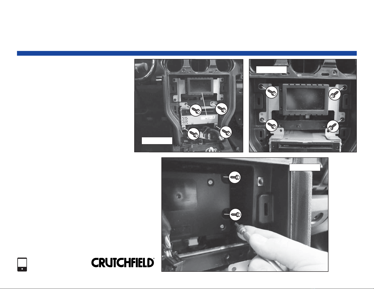
14. Remove four (4) 7mm screws securing
factory radio chassis (Figure 13).
Note: The removal of the display and
module is required to remove radio chassis.
The wiring harnesses are very short and are
difficult to disconnect. Use the following
steps to disconnect.
15. Remove four (4) 7mm screws securing
display to dash. Disconnect harness and
remove display (Figure 14).
16. Remove three (3) 7mm screws securing
module to sub-dash. Lift module,
disconnect harnesses on radio chassis and
remove chassis (Figure 15).
019 0021
Factory Radio Removal (continued)
4
FIGURE 13
FIGURE 15
Copyright 2018 Crutchfield Corporation
1-800-955-9094
TECHNICAL SUPPORT
Factory Radio Chassis
Display
Display
Module
Module
(2 of 3 screws shown)
FIGURE 14

019 0021
Receiver Installation
5
Copyright 2018 Crutchfield Corporation
1-800-955-9094
TECHNICAL SUPPORT
NOTES:
Please read first
• Check to make sure the Crutchfield receiver wiring
adaptor plugs into the vehicle receiver harness.
If the Crutchfield adaptor is incorrect, please call our
Technical Support Department at 1-800-955-9094.
1. Secure receiver to mounting bracket and make
wiring connections following instructions
supplied with the dash and wiring kit received
from Crutchfield.
2. Hold receiver assembly near dash. Connect
receiver wiring adaptor to vehicle harness.
Using the antenna adaptor, plug antenna lead
into rear of receiver. Plug in any other
accessories to be used with the receiver.
3. Slide assembly into dash and secure with
screws previously removed.
4. If installing a center dash speaker, proceed to
instructions on page 7 before reassembling dash.
5. Test receiver operation and reassemble dash by
reversing removal steps.
OEM Integration Dash Kit
Installation of an aftermarket receiver will require
modification to the dash. Please follow instructions
supplied with the dash kit to make modifications.

019 0021
Front Pillar Speakers
6
1. Starting at the top edge, pry out pillar
trimpanel to release two (2) retaining clips.
Twist panel retainer to release from panel
(Figures 1 & 2).
2. Pull bottom of trimpanel toward rear of vehicle.
Tilt trimpanel toward center of vehicle.
Disconnect wiring harness and remove panel.
3. Pry tweeter out to release three (3) clips and
remove tweeter (Figure 3).
4. Fabricate a speaker mounting bracket and
secure new speaker to bracket.
5. Make wiring connections following instructions
on page 13. Return to this page to complete
installation.
6. Secure speaker/bracket assembly to location.
7. Test speaker operation and reassemble pillar
area by reversing disassembly steps.
NOTES:
Please read first
• Instructions show factory size speakers or speakers
with adaptor brackets only. Cutting or fabrication (not
shown) will be required for other speaker sizes.
Copyright 2018 Crutchfield Corporation
1-800-955-9094
TECHNICAL SUPPORT
No speaker wiring adaptor is available at this time from
Crutchfield for this speaker location. It will be necessary to
splice wires in order to install an aftermarket speaker.
No speaker adaptor bracket is available at this time for this
location. A mounting bracket must be fabricated in order to
install an aftermarket speaker.
It is possible that the replacement speakers do not have
screws supplied. It may be necessary to acquire mounting
hardware.
IMPORTANT
!
FIGURE 1 FIGURE 2
FIGURE 3
Pillar Trimpanel
Pillar Trimpanel
Tweeter
Tweeter
Retainer
Retainer
Clips
Clips

019 0021
Center Dash Speaker
NOTES:
Please read first
• Instructions show factory size speakers or speakers
with adaptor brackets only. Cutting or fabrication (not
shown) will be required for other speaker sizes.
No speaker wiring adaptor is available at this time from
Crutchfield for this location. It will be necessary to splice
wires in order to install an aftermarket speaker.
IMPORTANT
!
1. Pry off glove box right trimpanel to release
three (3) clips and remove trimpanel (Figure 1).
2. Pry off center vent panel to release thirteen
(13) clips and remove vent panel (Figure 2).
3. Starting at the rear edge, pry up center dash
grille to release four (4) clips. Remove grille
(Figure 3).
4. Remove two (2) 7mm screws securing speaker.
Pull out speaker, disconnect and remove
(Figure 4).
5. Make wiring connections following instructions
on page 13. Return to this page to complete
installation.
6. Secure speaker to location with screws
previously removed.
7. Test speaker operation and reassemble by
reversing disassembly steps.
FIGURE 1
Center Vent Panel
Center Vent Panel
FIGURE 2
FIGURE 3
FIGURE 4
Copyright 2018 Crutchfield Corporation
1-800-955-9094
TECHNICAL SUPPORT 7
Center Dash Grille
Center Dash Grille
Glove Box Right Trimpanel

019 0021
Door Speakers
8
1. Starting at the front edge, pry out screw
cover behind door release to release one (1)
clip and remove screw cover. Remove one
(1) exposed 7mm screw (Figure 1).
2. Starting at the front edge, pry up power
options switch panel to release five (5) clips.
Disconnect wiring harness and remove panel
(Figure 2).
3. Remove one (1) 10mm screw exposed by
removal of power options switch panel
(Figure 3).
4. Remove two (2) 7mm screws along bottom
edge of door panel (Figure 4).
Continued on the next page.
Copyright 2018 Crutchfield Corporation
1-800-955-9094
TECHNICAL SUPPORT
NOTES:
Please read first
• Instructions show factory size speakers or speakers
with adaptor brackets only. Cutting or fabrication (not
shown) will be required for other speaker sizes.
FIGURE 1 FIGURE 2
FIGURE 3 FIGURE 4
Screw Cover
Screw Cover
Power Options Switch Panel
No speaker wiring adaptor is available at this time from
Crutchfield for the midrange location. It will be necessary to
splice wires in order to install an aftermarket speaker.
IMPORTANT
!

019 0021
Door Speakers (continued)
9
Check that wires do not interfere with window operation.
Test door lock and release operation.
SAFETY CHECK
!
Copyright 2018 Crutchfield Corporation
1-800-955-9094
TECHNICAL SUPPORT
5. Pry out sides of door panel to release seven
(7) clips. Lift panel, disconnect wiring
harnesses and door release cable. Remove
door panel (Figures 5 & 6).
6a. Midrange Removal & Installation:
Remove two (2) phillips screws securing
speaker to factory bracket. Cut wires
from speaker and remove (Figure 7).
Note: Bracket will be reused.
Make wiring connections to new speaker
following instructions on page 13.
Return to this page to complete
installation.
Secure speaker to bracket.
6b. Woofer Removal & Installation:
Remove three (3) 7mm screws securing
speaker. Pull out speaker, disconnect
and remove (Figure 8).
Secure new speaker to adaptor bracket.
Connect speaker wiring adaptor of
replacement speaker to vehicle speaker
harness.
Secure speaker/bracket assembly
to location.
7. Test speaker operation and reinstall door
panel by reversing removal steps.
FIGURE 5
FIGURE 6
FIGURE 7
Door Release Cable
Door Release Cable
(use needle-nose pliers for removal)
FIGURE 8

10
Rear Deck Speakers
1. Pry up door scuff plate to release seven (7)
clips and remove plate. Repeat this step on
the opposite side of vehicle (Figure 1).
2. Press in top of two (2) clips along front edge
of rear seat bottom cushion to release. Lift
cushion and pull toward the front of vehicle
to remove (Figure 2).
3. Fold down both rear seat back cushions.
4. Pry out rear side panel to release seven (7)
clips. Remove seat belt guide with seat belt
in place and remove rear side panel. Repeat
this step on the opposite side of vehicle
(Figures 3 & 4).
Continued on the next page.
019 0021
Rear Side Panel
Rear Side Panel
NOTES:
Please read first
• Instructions show factory size speakers or speakers
with adaptor brackets only. Cutting or fabrication (not
shown) will be required for other speaker sizes.
Copyright 2018 Crutchfield Corporation
1-800-955-9094
TECHNICAL SUPPORT
FIGURE 1
FIGURE 2
FIGURE 3
Door Scuff Plate
Door Scuff Plate
Clip
Clip
(1 of 2 shown)
(1 of 2 shown)
FIGURE 4

Rear Deck Speakers (continued)
019 0021
11
Copyright 2018 Crutchfield Corporation
1-800-955-9094
TECHNICAL SUPPORT
5. Pry out two (2) retaining clips along front
edge of rear deck panel (Figure 5).
6. Pull rear deck panel toward front of vehicle
to remove (Figure 6).
7. Remove three (3) 7mm screws securing
speaker. Pull out speaker, disconnect and
remove (Figure 7).
8. Secure new speaker to adaptor bracket.
9. Connect speaker wiring adaptor of
replacement speaker to vehicle speaker
harness. Secure speaker/bracket assembly
to location.
10. Test speaker operation and reassemble rear
of vehicle by reversing disassembly steps.
Make sure seats and seat belts are secured to
manufacturer’s specifications.
SAFETY CHECK
!
FIGURE 5
FIGURE 6
FIGURE 7
Rear Deck Panel
Rear Deck Panel
(1 of 2 clips shown)

Trunk Subwoofer
019 0021
NOTES:
Please read first
• Instructions show factory size speakers or speakers
with adaptor brackets only. Cutting or fabrication (not
shown) will be required for other speaker sizes.
1. Remove three (3) Torx T20 screws securing
enclosure cover panel. Remove panel
(Figure 1).
2. Remove one (1) Torx T40 screw and two (2)
1/2” bolts securing enclosure to body.
Disconnect wiring harness and remove
enclosure (Figures 2 & 3).
3. Remove one (1) 8mm screw inside cavity
on rear of enclosure and six (6) Torx T20
screws on front of enclosure (Figures 4 & 5).
4. Remove grille, then pry up subwoofer.
Disconnect wiring harnesses and remove.
5. Break off alignment pins on mounting
surface to allow proper fit of new speaker
(Figure 6).
6. Place new speaker in location and mark new
mounting holes. Remove speaker and drill
holes with a 1/8” bit.
7. Connect speaker wiring and secure speaker
to enclosure.
8. Test speaker operation and reassemble by
reversing disassembly steps.
12
FIGURE 3
FIGURE 1
FIGURE 2
FIGURE 5
FIGURE 4
Enclosure Cover Panel
Alignment Pin
Alignment Pin
(1 of 2 shown)
(1 of 2 shown)
FIGURE 6
(1 of 6 screws shown)
Copyright 2018 Crutchfield Corporation
1-800-955-9094
TECHNICAL SUPPORT
Always be careful when drilling or cutting in a vehicle. WEAR
EYE PROTECTION. Be aware of things such as wiring,
windows, fuel lines and safety devices. Check depth and
location to avoid damage to vehicle appearance.
CAUTION:
!

019 0021
Wire Splicing Guide
These methods can be used to make wiring connections if no receiver or speaker wiring adaptor is available.
Wire color information (if available) can be found on the next page.
13
Copyright 2018 Crutchfield Corporation
1-800-955-9094
TECHNICAL SUPPORT
- - - - - -
+ + ++ + + + + + + + + + + + + + + +
++ ++
++++
++
+
++
-
-
-
-
-
-
2. Twist wires from new
speaker to stripped
sections of factory wires
as shown making sure
polarity is correct.
- - - - - - - -
+ + + + + ++ + + + + + + + + + + + + + + +
+ ++
++ ++
++
++
++
-
-
-
-
-
-
Factory Wires
Factory Wires
Strip Out 1/2”
Strip Out 1/2”
New Wires
New Wires
Positive Wires
Positive Wires
Negative Wires
Negative Wires
First
First
Last
Last
CRIMP METHOD SOLDER METHOD
2. Strip end of each
wire back 1/2”.
1. Cut factory wires behind
factory speaker harness.
3. Twist each positive pair of
wires together and insert
in crimp cap. Repeat
step for negative wires.
4. Squeeze middle of cap
for tight connection.
5. Connect new wires to
speaker with spade
connectors.
1. Carefully strip out a 1/2”
section on each factory
speaker wire behind the
factory speaker harness.
3. Heat wires first with
soldering iron, then
touch solder to
wires for solid
connections.
4. Wrap wiring connections
with electrical tape.
5. Connect new wires to
speaker with spade
connectors.
Factory harness is removed. Save
harness if it is to be reconnected in
the future by this method.
New speaker wires are spliced into
factory wires behind harness.
Factory Wire
Factory Wire
New Speaker Wire
New Speaker Wire

14
Copyright 2018 Crutchfield Corporation
1-800-955-9094
TECHNICAL SUPPORT
019 0021
Wire Splicing Guide (continued)
Wire ColorWire Location
Left front door speaker positive (+): white or green, negative (-): white/brown or gray
Left front mid/tweeter (with amplifier) positive (+): green/blue, negative (-): gray/blue
Right front door speaker positive (+): white/violet or violet, negative (-): white/orange or yellow
Right front mid/tweeter (with amplifier) positive (+): violet/gray, negative (-): yellow/gray
Center dash speaker positive (+): green, negative (-): gray/yellow
Left rear door speaker positive (+): white/green or green/white negative (-): brown or brown/yellow
Right rear door speaker positive (+): brown/white or violet/white, negative (-): brown/blue or blue
Trunk subwoofer voice coil #1 positive (+): blue, negative (-): blue/white
Trunk subwoofer voice coil #2 positive (+): red, negative (-): red/white
Vehicle speed sense1(2.3L engine) PCM2, 95-pin plug, pin 12 or 26 - brown/green
(3.7L or 5.0L engine) - PCM2, 95-pin plug, pin 12 or 26 - yellow/orange
Reverse (+)1BCM3, 36-pin plug (J3), pin 11 - green/brown
Parking brake1Parking brake switch or BCM3, blue 52-pin plug (J5), pin 47 - white/violet
Foot brake Brake switch or BCM3, black 22-pin plug (J1), pin 1 - violet/white
Notes:
• If equipped with a factory amplifier, the amplifier will be located above the driver’s kick panel.
• ¹The radio replacement interface will also provide these signals.
• ²PCM (Power Control Module) is located under the hood next to the fuse box.
• ³BCM (Body Control Module) is located in the passenger’s kick panel.
NOTE: In most cases a speaker wiring adaptor is available from Crutchfield and splicing will
not be necessary. If no adaptor is available, use this chart as a guide to match and splice wires.
Table of contents
Other Crutchfield Car Stereo System manuals