Crysalli CR-1 User manual

Install Guide
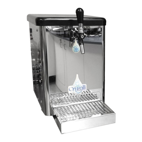
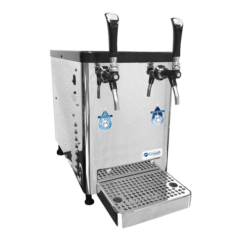
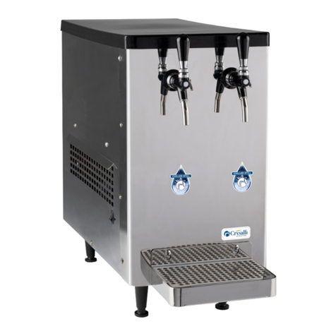
CT Sparkling & Still Countertop Chiller System
CR-1, CR-1PB & CR-2, CR-2PB
Crysalli Beverage Systems a division of WPD
1739 Sabre Street, Hayward, CA 94545
www.crysalli.com 510.732.0100
05132022
Register your
product online:

Crysalli Beverage Systems a division of WPD
1739 Sabre Street, Hayward, CA 94545
www.crysalli.com 510.732.0100
This page is intentionally le blank.

QTY Description Part Number Usage
1 3/8 Tube x 9/26-24 Female Adapter PSEI6012U9 Quick connect fitting adaptor to an anglestop
2 1/2” Tube to 3/4” NPT PSEI02026 Adaptor reducers for filter system inlet and outlet
2 5/8” (1/2”) Stem to 3/8” tube PP062012W Adaptor reducers for filter system inlet and outlet
8 JG 90 elbow 3/8” smooth to 3/8” PP221212W For trunkline outlet of unit and water inlet
12 JG 3/8 Locking Clips PIC1812R Collet locking clip for JG fittings
1 Splice Barb 1/4” to 1/4” 9001 Use this fitting for adding additional CO2 line
4 10.5 Oetiker Clamps 0105 Use with 9001 for 1/4” ID braded CO2 hose and barb
1 12’ Section of 3/8” OD tubing PE-12-EI Water inlet tubing, filter system to chiller
1 8’ sections of 1/4” ID braided hose 172-04804-00 Additional CO2 hose, if needed. Do not use in JG fittings
6 8” Zip Ties S-14041
Crysalli Beverage Systems a division of WPD
1739 Sabre Street, Hayward, CA 94545
www.crysalli.com 510.732.0100
CR-KIT-CT Install Kit
Ordered Separately
Install Kit for CR-1 & CR-2
Countertop Chiller Systems
This Kit is designed to supply you with
the fittings & parts you may need to
complete the install of an CR-24FC
Filter system with 3/4” inlet and outlet
fittings to a Crysalli CR-1 or CR-2 chiller
unit.
Reference the Crysalli Countertop
system Quick Install Guide for part
usage and install details.
Connections: The water inlet is
the 3/8” quick connect fitting on
the botton of the chiller. Use the
PP221212W.
The clear hose is the overflow drain
hose.
The 1/4” white braided hose with
fitting is the CO2 inlet. The CR-PC160
CO2 Regulator connects to this.
Water bath must be manaully filled
with water.
Always reference local plumbing codes
to determine if a backflow preventer is
required and to check the type/style of
backflow preventer that is accepted as
well as the plumbing location it needs
to be placed in.
Crysalli does not include backflow
preventers in the install kits because of
variability in requirements.
Backflow devices should be sourced
from local plumbing stores.
For questions or assistance with install
contact Crysalli 510-732-0100 or your
local Distributor.

1. Select a location for your chilled
water dispenser, keeping in mind
the unit needs air space behind it
and to the sides. Place unit within
6’ of water filter connection &
120-volt electrical outlet. Make
consideration for proximity of a
floor sink for the overflow drain
hose.
2. Locate the CR-KIT-CT install kit
and unpackage and take note of
the fittings, water regulator and
hose supplied to complete the
install.
3. Locate the CR-24FC water filter
system head and filter cartridges.
Mount the water filter system in
an accessible location with at
least 3” of space below the filters
for service. The filter system
has a 3/4” fpt inlet and outlet,
locate the adaptor fittings in the
install kit to reduce down to 3/8”
(PSEI02026 1/2” tube to 3/4” mpt,
and PP062012W reducer 5/8” stem
to 3/8” tube). Locate the PE-12-EI,
12’ role of 3/8” OD hose. This hose
should be used for the inlet and
outlet of the filter system and to
feed into the inlet of the chiller. Do
not use the 1/4” braided hose for
water connections or with John
Guest fittings, it will not hold. The
1/4” braided hose is for extra CO2
line only.
4. Locate the PSEI6012U9 3/8”
anglestop adaptor fitting from the
install kit. This fitting replaces the
compression nut and ferule ring
on the angle stop and is meant to
be hand tightened to the angle
stop outlet so you have a 3/8”
quick connect fitting outlet to the
filter system. Measure and cut a
length 3/8” OD hose to connect
from the angle stop to the inlet
of the filter system. Consult
local plumbing codes for use
and requirements of a backflow
device.
5. The water inlet for the chiller is
a 3/8” quick connect push-in
fitting, located on the bottom
base of the unit near the front
legs. Connect the end of 3/8”
hose from the water filter system
to the PP221212W elbow swivel
3/8” tube to 3/8” stem fitting and
connect that fitting into the inlet
of the chiller.
6. Locate the 8”x8” box for CR-PC160
High Pressure CO2 regulator.
Unbox this regulator and locate
the 1/4” nylon washer taped to the
packaging. The 8’ length of 1/4”
white braded hose extending out
the base of the chiller is the CO2
hose. It has a stainless-steel flare
nut on the end. Rout this hose to
the location of the CO2 tank. If
extra length is required locate the
6’ of 1/4” hose, 1/4” barb union
and 9.5 Oetiker clamps from the
install kit and splice the line in.
The 1/4” nylon washer should be
inserted into the SS flare nut fitting
at the end of the hose and then
connect to the CO2 Regulator.
7. The clear hose coming out the
bottom of the chiller is overflow
water bath drain hose. It is best
to run this hose to a floor drain
or other waste drain. You will get
some draining from this hose
during the install start-up of the
chiller as the water bath freezes an
ice bank.
8. Turn on water at the filter system
and flush the water filters of air via
the flush valve on the filter system.
Check for leaks.
9. Fill water bath: Remove lid and
fill water bath with non-filtered/
non-soened tap water, fill up
no less than 1/4” to top of white
standpipe. This is the vertical
white tube in the water bath that
is connected to the clear overflow
hose.
10. Plug unit power cord into 120-volt
outlet. Toggle the on/o rocker
switch to the “on” position. Fan
and compressor will turn on. Fan
and compressor will automatically
turn o when a complete ice bank
is made and cycle on and o to
maintain it.
11. Unit will take between 3-4 hours
to make a complete ice bank. 1/3
of the water bath should freeze
over the refrigeration coils to form
a block of ice. On the CR-1 models
the ice bank forms along the
right side of the bath. On the CR-2
models the ice bank forms an “n”
shape around the outside edges of
the bath.
12. Open CO2 at the CO2 tank
by turning knob on tank
counterclockwise. Adjust regulator
via the set screw on the front
between 75 PSI. And check for
leaks.
13. Pull open the still water and
sparkling water faucets to run
water through the system. You will
need to run the sparkling water
faucet for several minutes to cycle
the carbonation system before full
sparkling water will dispense.
14. Once unit has built the ice bank
you are ready to dispense chilled
still and sparkling water. Adjust
the flow control handles on the
faucets for your preferred flow
rate.
Crysalli Beverage Systems a division of WPD
1739 Sabre Street, Hayward, CA 94545
www.crysalli.com 510.732.0100
CR-1 & CR-2 Quick
Installation Guide
Instructions

Crysalli Beverage Systems a division of WPD
1739 Sabre Street, Hayward, CA 94545
www.crysalli.com 510.732.0100
Countertop Series
Start-up and Install
Check List
Start-up Sequence:
☐ Confirm the water bath is filled
☐ Turn water on to unit (confirm
flow from faucets)
☐ Plug unit in and toggle on/o
switch to the on position.
☐ Turn CO2 on at tank (carb tank
may need to be bled).
Water Filters, CR-24FC and
CR-24FCP:
☐ Water on. Filters flushed via the
flush valve and flowing water.
☐ Water pressure at/through
water filter system above 50 PSI
and not dropping o.
☐ All connections leak-free.
CO2:
☐ CO2 hose from unit: flare nut
connection on end of CO2
hose tight to CR-PC160 CO2
Regulator (be sure to use nylon
washer supplied with reg in
fitting).
☐ CO2 reg connected to CO2 tank
(card board/plastic washer
used) tight and leak-free.
☐ CO2 tank full, opened all the
way and set to 75 PSI.
Countertop Chiller:
☐ Faucets tight and positioned vertically. Handles tight and positioned
front facing.
☐ Water bath filled with water up to the top of the WHITE stand pipe.
☐ Unit on and plugged into a dedicated 120V outlet.
☐ Ice bank formed/forming on refrigeration coils in water bath. Unit
cycling on and o properly to maintain ice bank. Unit will take 2 hours
to form full ice bank aer initial start-up.
☐ Sparkling water; cold, carbonated. Tastes clean and pure. Adjust flow
control on faucet to slow flow rate.
☐ Run a few liters of sparkling water, is carb pump cycling on and flow
consistent without gassing out. Carb pump will cycle on aer 1.5 liters
of sparking water is poured. Carb pump should run for 7-14 seconds.
☐ Still water: cold and consistent flow. Tastes clean and pure. Adjust flow
control on faucet to needs.
☐ Check clearances; Unit should be able to ventilate hot air out sides
and breath fresh air in the back. Unit free of obstructions around it and
can vent.
☐ Air filter in rear of machine is accessible
☐ Water inlet connection to unit leak free and not pinched o anywhere
☐ Agitator pump agitating bath water.

Crysalli Beverage Systems a division of WPD
1739 Sabre Street, Hayward, CA 94545
www.crysalli.com 510.732.0100
Countertop Chilled
Water Dispenser Quick
Installation Guide
Cylinder pressure. If needle drops into
“red area” cylinder is empty. Change
CO2 cyllinder.
To adjust high pressure regulator:
Loosen the locking nut using a regular
screwdriver, turn adjustment screw
clockwise to increase pressure;
counterclockwise to decrease. When
needle is positioned at the right pressure,
tighten locking nut.
Set gauge
75 PSI
CO2 Pressure to
carbonator tank in unit
Plastic
washer
Secure line to regulator by
tightening nut
Lock nut
Adjusting screw
CO2 Line from regulator to
carbonator tank inside unit
Remove lid & fill
water bath to top of
stand pipe
Trunk line to dra tower
Drain hose to floor drain
Condensation will build inside unit &
must drain or unit will overflow
Note: Carbonation levels will be low until the
machine has developed a suicient ice bank to
reduce temperature of dispensed drink.
This can take up to 4 hours.

Crysalli Beverage Systems a division of WPD
1739 Sabre Street, Hayward, CA 94545
www.crysalli.com 510.732.0100
Installing the Water Filter System
& Angle Stop Adaptor
Locate the 2 PSEI012026 1/2” to 3/4” MPT fittings and
PP062012W 5/8” stem to 3/8” tube adaptor fittings from the
UCM Install Kit, along with 2 red locking clips. These are your
inlet and outlet fittings for the twin water filter system. Wrap
some Teflon tape around the threads of the 3/4” MPT fitting,
attach them to the two ends of the filter manifold. Push the
smaller adaptor fittings on to the larger fittings and twist lock
the larger fittings collet. Push the blue 3/8” hose ends into
these fittings and apply the red locking clip.
The UCM Install Kit comes with 12’ of the blue or black
PE-12-EI tubing. Cut this to appropriate length for inlet and
outlet plumbing needs.
Locate the PSEI6012U9 angle stop adaptor in the UCM
Install Kit. Locate the angles stop water source feeding the
system, remove the compression nut and ferule ring from it
and replace with the PSEI6012U9 fitting.
PSEI012026
PP062012W
Note: The Install Kit comes with a 1/4” white braided hose
as well, this is not for the water connections. It is for the
CO2 only and cannot be used with John Guest fittings.
Using the braided hose in a JG fitting can result in leaks
and flooding.
Note: Crysalli does not provide
external backflow preventers. Always
reference local plumbing codes for
the use requirement of a backflow
preventer, as well as type and location
within the system.
To UCM
Chiller unit
Mount the filter manifold on the
wall with at least 3” of clearance
at the bottom of the filters.

Crysalli Beverage Systems a division of WPD
1739 Sabre Street, Hayward, CA 94545
www.crysalli.com 510.732.0100
Water Inlet connection
CR-1 and CR-1PB
Locate the PP221212W elbow 3/8”
hose to tube fitting and a red locking
clip. Connect this fitting to the end of
3/8” hose from the filter system and
water reg. Then connect this to the
water inlet on the chiller.
Water inlet connection: 3/8” push-in
hose connection.
Located at the base of the chiller, near
the front, next to the 1/4” braided CO2
hose, 3/8” clear overflow drain hose
and 9’ electrical cord.
Push tube end of fitting into water inlet
connection on the chiller.

Crysalli Beverage Systems a division of WPD
1739 Sabre Street, Hayward, CA 94545
www.crysalli.com 510.732.0100
Water Inlet connection
CR-2 and CR-2PB
Locate the PP221212W elbow 3/8”
hose to tube fitting and a red locking
clip. Connect this fitting to the end of
3/8” hose from the filter system and
water reg. Then connect this to the
water inlet on the chiller.
Connections found on back side of
CR-2 and CR-2PB model
• 120 Volt electrical cord and plug,
NEMA 5-15
• CO2 inlet connection: 1/4” braided
hose (8’) with flare nut end
connection
• Water inlet connection: 3/8” push
in hose connection.
• On/o Switch
• Safety LED light
• Air filter
Water Inlet hose connection made
with PP221212W elbow swivel fitting
and 3/8” hose from the water filter
system.

Crysalli Beverage Systems a division of WPD
1739 Sabre Street, Hayward, CA 94545
www.crysalli.com 510.732.0100
Connecting CO2 and
Filling Water Bath
Step 1: The hose for the CO2 connection is 6’ long, 1/4” braided hose with a 1/4”
flare nut on the end extending out from the chiller near the water inlet. Route
this hose to the location of the CO2 tank. If additional hose is required, the UCM
Install Kit comes with an additional 8’ of 1/4” braided hose*, a 1/4” barb union
and 10.5 oetiker clamps to extend it.
*WARNING: Do not use this extra 1/4” braided hose with John Guest fittings for
the water inlet or water filter connection, it is not the correct OD or tube type to
work with these fittings and will result in leaks.
If using dedicate CO2 tank, locate the CR-PC160 primary high pressure CO2
regulator. Unbox it and be careful to locate the 1/4” nylon washer taped to the
packaging. Insert this washer into the flare nut on the end of the hose and thread
it on to the 1/4” mpt flare on the CO2 reg. Locate paper washer with CO2 tank
and thread CO2 reg to tank, making sure its tight.
For bulk CO2 tank use or shared CO2 systems, use the CR-S115
secondary high pressure CO2 regulator to regulate.
Step 2: Route the clear over flow water
bath drain hose from the back of the
unit to a floor sink or floor drain.
The water bath must be filled with
water for the system to work and build
an ice bank. This water is not used for
consumption, it is only used to form an
ice bank around the refrigeration coils
and chill the water flowing through the
water cooling coils. Water will drain
from the over flow hose upon initial
start up as the ice bank forms. Aer
that only periodic condensation may
drip from the over flow hose.
Remove the lid of the chiller to expose
the water bath area. Fill this area with
water (preferably non-filtered) up to
the white stand pipe, covering the carb
tank, water coils and refrigeration coils.
CR-PC160
CR-S115
Flare nut
with nylon
washer in it
CR-UCM1
Fill with 4 gallons of water
or up to the white stand pipe
CR-UCM2
Fill with 6 gallons of water
or up to the white stand pipe
CR-UCM2 ice formation
around ref coils

Crysalli Beverage Systems a division of WPD
1739 Sabre Street, Hayward, CA 94545
www.crysalli.com 510.732.0100
Exploded View of
X0101 Faucet Handle
Pivoting
handle nut Bonet nut. Loosens with use. Check and tighten daily.
Friction washer
Ball washer
Stainless lever arm
Body gasket Spring
Nozzle
Shank
Shank sleeve
Coupling nut.
Holds faucet to
shank.
Flow control bullet
with 2 clear gaskets
Plunger with air vent holes and rear gasket.
If water leaks from nozzle, check rear gasket.
Adjustment arm assembly holds
plunger in place and moves it to
adjust flow rate
The faucet handle is self-closing when released. The internal spring creates
this tension to close the valve and shut o flow. The spring can be removed if
self-closing is not desired.
Coupling nut holds faucet body
to shank. Use faucet wrench to
loosen and tighten.
Flow control
X0102 Rear nut fitting
1/4” barb. Used on
CR-1, CR-2 and other
countertop models.
Horizontal position is full
open. Downward or upward
position, quarter turn restricts
or slows flow from the faucet.
Flow can be completely shut
o if turned too far back.
Handle:
10-2055-90
Pivoting handle
nut 10-2220-80
Air vent
Nozzle
bent or straight
Flow control adjuster
Outer ring
Adjustable hex fitting
Using a 2.5 hex wrench to
adjust flow rate

Crysalli Beverage Systems a division of WPD
1739 Sabre Street, Hayward, CA 94545
www.crysalli.com 510.732.0100
Push Button Series Flow Control
Adjustment, CR-1PB & CR-2PB
The push button (PB) models have a flow control set screw
that can be found on the top of the Solenoid valve for each
valve. Flow rate adjustments should be made with the unit
on, cold, CO2 set to 74 PSI and filling into a glass.
To access, remove the lid of the chiller to expose Solenoid
valves. The set screw is the taller notched screw betweenthe
two Philips screws for the bracket.
Flow control adjustment screw.
Use a flat head screw driver to turn.
Right to tighten and slow
the flow.
Le to loosen and speed
the flow up.

Crysalli Beverage Systems a division of WPD
1739 Sabre Street, Hayward, CA 94545
www.crysalli.com 510.732.0100
CO2 Information CO2 tanks can be sourced and
refilled from local beverage CO2
companies (both bulk and/or tank)
and welding supply companies.
On average, 1lb of CO2 will
be used for every 5 gallons of
sparkling water. A 20lb tank should
carbonate 100 gallons (12,800oz or
378 liters) of sparkling water.
WARNING: CO2 can be dangerous. CO2 cylinders contain high pressure
gas which can be hazardous if not handled properly. Follow all CO2
regulator instructors (found with CO2 regulator) and other handling
instructions from the CO2 tank supplier.
CR-PC160 High
Pressure CO2
Regulator 0-160 PSI
Attaches to 5-100lb CO2 tanks. Set at 75 PSI as a starting point.
Note: Low-pressure beer regulators 0-60 PSI will not work properly
with Crysalli.
Fill level gauge: Volume of CO2 in
tank. Tank is empty when needle is
in the red zone or zero.
1/4” Male flare connection to
Crysalli chiller. Use nylon washer
supplied with regulator in fitting.
Output pressure gauge: Shows CO2
output pressure settig.
Set to 75 PSI.
Threaded connection
to CO2 tank.
Pressure adjustment screw and
locking nut.

Model Number:
Install Date:
Serial Number:
Installer/Servicer:
CR-1 & CR-2 Countertop Cleaning and
Maintenance Recommendations
Crysalli Beverage Systems a division of WPD
1739 Sabre Street, Hayward, CA 94545
www.crysalli.com 510.732.0100
Daily:
☐ Wipe down the unit or dra tower, cleaning and
drying all surfaces. (Use window cleaner on
mirrored and chrome finishes).
☐ Clean and dry drain pan and drain grate. Check
that water is draining, pour warm water down
drain if necessary.
☐ Check over faucets for action and hand tighten
any loosened handles or nuts on them. A
wobling faucet indicates the faucet body is
loosening from the shank which can result in
a leak, faucet coming o or stripping the teeth.
Use a shank wrench to tighten the shank nut to
the faucet.
☐ Check flow from faucet, loosen, readjust, and
tighten flow control knob as needed.
☐ Check that flow, temperature and carbonation
of water poured from the unit are consistent to
average use.
Weekly:
☐ Clean the faucets by wiping them down. If there
is any scale or slime submerge them in cleaners/
sanitizer and use a brush on them.
☐ Check CO2 level at CO2 tank.
Monthly:
☐ Clean the air filter. Remove it to brush down and
wash o dust and dirt, then reattach.
☐ Check for good water pressure at the water filter
system by running water from flush valve on
filter.
☐ Visually check pre-filter in clear bowl on water
filter system (if applicable) to determine if it
needs replacing. Use only EPC5-10 replacement
pre-filter cartridge.
Quarterly:
☐ Check the water bath level, either top o or
drain, clean and refill.
Semianually:
☐ Change the water filters. Use only 4FC
replacement filter cartridges.
☐ Drain water bath, clean and refill with new water.
☐ Remove and disassemble faucets for cleaning
and inspection.
Annually:
☐ Inspect internal water bath components such as
agitator/re-circ pump and blade, check valves
for CO2 and water, and all hose connections.
☐ Flush and rinse system with food safe sanitizer
(this work should be performed by a certified
service tech).

Crysalli Beverage Systems a division of WPD
1739 Sabre Street, Hayward, CA 94545
www.crysalli.com 510.732.0100
This page is intentionally le blank.

Distributor/Dealer:
Model Number:
Install Date:
Serial Number:
Install Company:
Or register online:
Crysalli Beverage Systems
1739 Sabre Street, Hayward, CA 94545
Phone: 510-732-0100 Fax: 510-732-0155
Website: www.crysalli.com
Name of Customer/Business & Address:
Phone:
Limited Express Warranty
Crysalli Beverage Systems (herinaer referred to as Crysalli) warrants for a period of 12 months from
installation date (except as limited below) that new Crysalli water systems, towers and faucets (herinaer referred to
as Product) manufactured by ICI for Crysalli shall be free of defects in material or workmanship under normal and
proper use and maintenance as specified by Crysalli and upon proper installation and start-up in accordance with the
Quick Install Guide and Owners Manuals. Any accompanying water filtration system is warranted by the Manufacture
of that product only, not by Crysalli, ICI or WPD.
The obligation of Crysalli under this limited express warranty is limited to the repair or replacement of parts,
components, or assemblies that in the opinion of Crysalli are defective. This warranty is further limited to the cost of
parts, components or assemblies and standard straight time labor charges at the servicing location. Replacement
parts are warranted for 90 days or the balance of the original warranty period, whichever is longer. The foregoing
constitutes Crysalli’s sole obligation and the consumer’s exclusive remedy for any breach of this warranty. Crysalli’s
liability under this warranty shall in no event be greater than the actual purchase price paid by the consumer for the
Product. Additional expenses including, without limitation, service travel time, overtime or premium labor charges,
accessing or removing the Product, or shipping are the responsibility of the consumer.
The foregoing limited express warranty shall not apply to costs for: (1) periodic or routine maintenance
including water filter change outs, (2) repair or replacement of the Product or parts due to normal wear and tear, (3)
defects or damage to the Product or parts resulting from clogged water filters, misuse, abuse, neglect or accidents,
(4) defects or damage to the Product or parts resulting from improper or unathorized alterations, modifications, or
changes; (5) defects or damage to any Product that has not been installed and/or maintained in accordance with the
Owners Manual, Quick Install Guide or technical instruction provided by Crysalli, ICI or WPD; and (6) any work being
performed by non-authorized service agents.
THIS LIMITED EXPRESS WARRANTY IS IN LIEU OF ALL OTHER WARRANTIES OR GUARANTEES OF ANY KIND,
EXPRESSED OR IMPLIED, INCLUDING ANY IMPLIED WARRANTY OF MERCHANTABILITY OR FITNESS FOR A PARTICULAR
PURPOSE. IN NO EVENT SHALL CRYSALLI, WPD, OR ICI BE LIABLE FOR ANY SPECIAL, INDIRECT, INCIDENTAL OR
CONSEQUENTIAL DAMAGES. Upon the expiration of the warranty period, Crysalli’s liability under this limited express
warranty shall be terminated. The foregoing limited express warranty shall constitute the sole liability of Crysalli, WPD
and ICI and the exclusive remedy of the customer or user.
To secure prompt and continuing warranty service, the warranty registration card or online form must be
completed and sent to Crysalli within thirty (30) days from install date. Complete the following registration card and
send to Crysalli/WPD to below address. Retain a copy for your record.
Other manuals for CR-1
1
This manual suits for next models
3
Table of contents
Other Crysalli Chiller manuals
Popular Chiller manuals by other brands

AERMEC
AERMEC FHX Technical manual

Koolatron
Koolatron BKC5L owner's manual

Haier
Haier CA0065EANR Service manual

York
York YCAV0267E Installation operation & maintenance

Aircold
Aircold WLA Compact 230/1/50 TRANSLATION OF ORIGINAL INSTRUCTIONS

Daikin
Daikin EWAQ~G-SS Installation, operation and maintenance manual

Trane
Trane CXAJ065 Installation, operation and maintenance

AERMEC
AERMEC WRL 200 installation manual

Daikin
Daikin WGZ030DW Installation and maintenance manual

Mueller
Mueller PMC 40/50 Installation and operation manual

Samsung
Samsung AG010KSV Series installation manual

Pfannenberg
Pfannenberg CCE 6101 Operating and maintenance instructions