DESCRIZIONE DEI COMPONENTI
• COMPONENTI CIRCUITO FRIGORIFERO
COMPRESSORE
Compressori ermetici, con protezione termica incorporata,
di tipo scroll.
CONDENSATORE
Del tipo a piastre in acciaio inox AISI 316, isolato ester-
namente nelle versioni a pompa di calore per ridurre le
dispersioni termiche.
Non presente sulla versione NBW E.
EVAPORATORE
Del tipo a piastre in acciaio inox AISI 316, isolato esterna-
mente per ridurre le dispersioni termiche ed evitare la for-
mazione di condensa.
VALVOLA TERMOSTATICA
La valvola, con equalizzatore esterno posto all’uscita del-
l’evaporatore, modula l’afflusso di gas all’evaporatore in
funzione del carico termico in modo da assicurare un suffi-
ciente grado di surriscaldamento al gas di aspirazione.
FILTRO LINEA LIQUIDO
Di tipo meccanico realizzato in ceramica e materiale igro-
scopico, in grado di trattenere le impurità e le eventuali
tracce di umidità presenti nel circuito frigorifero.
RUBINETTI (solo per NBW E)
Rubinetti sulla linea del liquido e sul premente.
VALVOLA SOLENOIDE (solo per NBW E)
Organo d’intercettazione inserito sulla linea del liquido.
SEPARATORE DI LIQUIDO (solo per NBW E)
Posto in aspirazione al compressore a protezione da even-
tuali ritorni di liquido, partenze allagate, funzionamento
con presenza di liquido.
•TELAIO
STRUTTURA PORTANTE
Realizzata in lamiera di acciaio zincato a caldo, di adegua-
to spessore, è verniciata con polveri poliestere.
• COMPONENTI ELETTRICI
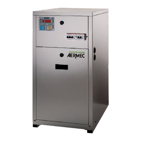
TASTIERA DI COMANDO
Consente il controllo completo dell’apparecchio. Per una
più dettagliata descrizione si faccia riferimento al manuale
d’uso.
SEZIONATORE BLOCCAPORTA
Per sicurezza è possibile accedere al quadro elettrico solo
togliendo tensione agendo sulla leva di apertura del quadro
stesso. E’ possibile bloccare tale leva con uno o più lucchetti
durante interventi di manutenzione per impedire una indeside-
rata messa in tensione della macchina.
QUADRO ELETTRICO
Contiene la sezione di potenza e la gestione dei controlli e
delle sicurezze (standard IP 20). È conforme alle norme EN
60335-2-40
• COMPONENTI DI SICUREZZA E CONTROLLO
PRESSOSTATO DI BASSA
A taratura fissa, posto sul lato a bassa pressione del circuito
frigorifero, arresta il funzionamento del compressore in caso
di pressioni anomale di lavoro.
SPIA DEL LIQUIDO (di serie su tutte le versioni E, oltre che i
modelli 307 - 407 sia standard che pompa di calore)
Serve per verificare la carica di gas frigorifero e l’eventuale
presenza d’umidità nel circuito frigorifero.
PRESSOSTATO DI ALTA
A taratura fissa, posto sul lato ad alta pressione del circuito
frigorifero, arresta il funzionamento del compressore in caso
di pressioni anomale di lavoro.
PRESSOSTATO DIFFERENZIALE
È montato tra l’entrata e l’uscita dello scambiatore e, in caso
di portata d’acqua troppo bassa, ferma il compressore.
DESCRIPTION OF COMPONENTS
•COMPONENTS OF REFRIGERANT CIRCUIT
COMPRESSOR
Hermetic compressors (scroll type) with incorporated ther-
mal cut-out device.
CONDENSER
Plate type condenser made from stainless steel AISI 316,
featuring external insulation in heat pump versions to redu-
ce heat loss.
Not present on the NBW E version.
EVAPORATOR
Plate type evaporator made from stainless steel AISI 316,
featuring external insulation to reduce heat loss and to pre-
vent the formation of condensate.
THERMOSTATIC VALVE
Valve with external equaliser at the evaporator outlet; regu-
lates gas flow to the evaporator according to the heat load,
thereby ensuring sufficient heating of suction gas.
LIQUID REFRIGERANT FILTER
Mechanical filter made from ceramic and hygroscopic mate-
rial, designed to capture impurities and all residual moisture
in the cooling circuit.
COCKS (only for NBW E version)
Cocks on liquid line and on compressor outlet line.
SOLENOID VALVE (Only for NBW E version)
Intercepting part on liquid line.
LIQUID SEPARATOR (Only for NBW E version)
Fitted before the compressor in the suction line to protect
the compressor from wet operation, liquid slugging and floo-
ded start.
•FRAME
CHANNEL FRAME
Constructed from sturdy, hot-galvanised sheet metal, painted
with stoved polyester powed.
• COMPONENTI ELETTRICI
CONTROL KEYBOARD
For complete control of unit functions. For more detailed
information, refer to the instruction manual.
DOOR LOCK DISCONNECTOR
For safety's sake it is only possible to access the electric panel
after cutting off the power supply using the lever that opens the
panel itself. This lever can be fastened with one or more locks
during maintenance operations, to prevent power from being
restored to the machine accidentally.
SWITCHBOARD
Contains the power supply and management of controls and
safety devices (standard IP20). Made to EN standard 60335-
2-40.
• SAFETY AND CONTROL DEVICES
LOW PRESSURE SWITCH
Fixed setting switch, installed on the low pressure side of the
cooling circuit; stops compressor in the event of anomalous
operating pressure values.
SPY GLASS (di serie su tutte le versioni E, oltre che i model-
li 307 - 407 sia standard che pompa di calore)
For checking the refrigerant gas load and the presence of
moisture in the cooling circuit.
HIGH PRESSURE SWITCH
Fixed setting switch, installed on the high pressure side of
the cooling circuit; stops compressor in the event of anoma-
lous operating pressure values.
DIFFERENTIAL PRESSURE SWITCH
Installed between the heat exchanger inlet and outlet, this
switch stops the compressor in the event of too low water
supply.
NBW Cod. 6611410 7
