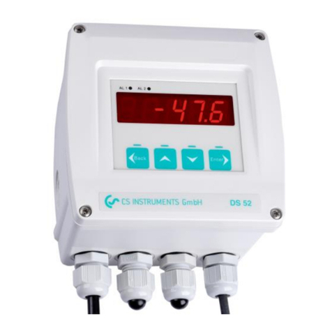
CS Instruments DS 52 User manual

V1.06 EN
1
Instruction Manual
Digital Display DS 52
in wall housing
Order-no: 0500.0009
for 0/4…20 mA sensors

V1.06 EN
2
Table of content Page
Introduction 2
Safety instructions 3
Short-form instruction DS 52 with 0/4…20 mA sensors 4
Menu with all functions 7
Lock operation menu, enter code, lock alarm values 8
Calibration/adjustment 9
Warranty 9
Technical data 10
Order information 10
Contact 11
Introduction
Dear customer,
Thousands of customers buy our high standard products every year. There are a few
good reasons for doing so:
•The cost-performance ratio - reliable quality at a fair price.
•We have the ideal solutions for your measuring tasks based on our
expert experience gained over 20 years.
•Our high-quality standard.
•Of course, our instruments carry the CE symbol required by the EU.
•We issue calibration certificates and hold seminars.
•Also after the purchase we do not leave you out in the cold - we offer
a good after sales service.
Our service grants you a fast help.
Measuring instrument conforms with DIN EN 61326

V1.06 EN
3
9. Safety instructions
Observe measuring ranges of the sensors!
Observe the admissible storage and transportation temperature as well as the
permitted operating temperature (e. g. protect the instrument from direct insolation)
Adjustments and calibrations should only be carried out by qualified employees from
the measurement and control technology branch.
We offer you to take back the instruments DS 52, which you would like to dispose of.
The manufacturer cannot be held liable for any damage which occurs as a
result of non-observance or non-compliance with these instructions. Should the
device be tampered with in any matter other than a procedure which is
described and specified in the manual, the warranty is cancelled, and the
manufacturer is exempt from liability.
CS Instruments GmbH offers no guarantee for the suitability for any other
purpose and is not liable for errors which may have slipped into this operation
manual. CS Instruments GmbH is also not liable for consequential damage
resulting from the delivery, capability or use of this device.
Initiation (electrical connection)
When operating electrical instruments it is unavoidable that certain components
are energised dangerously. Work at electrical installations or equipment is only
allowed to be carried out by electrical technicians or instructed staff under the
guidance and suvervision of an electrical technician according to the electrical
regulations.
Warning
Any non-observance of the warning notes may cause grievous bodily harm or
property damages. Qualified staff has to be well familiar with all warnings
according to this instruction manual. The correct and safe operation is subject
to a proper transport, professional installation and accurate initiation. The
following notes on safety are applied in order to stress safety relevant
procedures in this instruction manual - every note is marked by a corresponding
icon.
This symbol means: Note!
"Note" marks activities or procedures which have a fundamental influence
on correct operation. Any non-observance may possibly lead to subsequent
damages.
This symbol means: Warning!
"Warning" indicates activities or procedures which may lead to a safety
risk for persons and property damages in case of non-observance.

V1.06 EN
4
10. Short-form instruction DS 52 with 0/4…20 mA sensors
Power supply and alarm connection:
Pinning
Supply
13
14
15
110 VAC / 230 VAC
PE
N
L
24V dc
(-)
+24 V
10.1 Connection of CS Instruments sensors
Supply
110VAC / 230 VAC (50/60 Hz)
24 V DC
Attention!
Mains voltage!
NC und COM are closed
in case of:
- alarm exceeding
- voltage drop
- sensor break
Supply
Supply
Supply

V1.06 EN
5
7 8 9 101112131415
1 2 3 4 5 6
Sensor SupplyA1 - 2 A1 - 1
PE
N
L
V+
GND
I
I+
I-
SIG
1
2
3
4
5
FA 510
Braun / brown
Blau / blue
Grau / grey
CS Sensor
Terminal connector M12
7 8 9 101112131415
1 2 3 4 5 6
Sensor SupplyA1 - 2 A1 - 1
PE
N
L
V+
GND
I
I+
I-
SIG
1
2
3
4
5
FA 515
Braun / brown
Blau / blue
*
*
CS Sensor
Terminal connector M12
* A bridge circuit is inserted ex factory. For signal transfer please remove the
bridge circuit and attach the connection cables. Attention: Current loop has to
be closed!

V1.06 EN
6
10.2 Connection of third party sensors
DS 52 has one analogue sensor input for connection of sensors with 0/4…20
mA signal. The sensor input is configured on our premises (according to the
customer’s specification in the order).
Sensors with 0/4…20 mA-current signal are connected as follows:
2.3 Connection option alarm unit
7 8 9 101112131415
1 2 3 4 5 6
Sensor 230 VACA1 - 2 A1 - 1
PE
N
L
V+
GND
I
I+
I-
SIG
*
0
1
2
5
4
3
Netzanschlussleitung
Supply cable
grün-gelb / green-yellow
blau / blue
braun / brown
grau
grey
schwarz / black
Lampe / lamp
braun / brown
Summer / buzzer
Base Light Modul
DS 52
V+ max:
24 VDC
100 mA
* A bridge circuit is inserted ex factory . For signal transfer please remove the
bridge circuit and attach the connection cables. Attention: Current loop has
to be closed!
Supply
Supply

V1.06 EN
7
11. Menu with all functions
The operation is effected via 4 keys: and as well as ,
in order to access the menu/to confirm selection and
The operation in detail:
-45,0 currently measured value
press for the duration of 3 seconds
AL - 1
8.0
alters
At - 1
nOr
alters
press shortly
HY - 1
2.0
alters
press shortly
AL - 2
8.0
alters
At - 2
nOr
alters
press shortly
HY - 2
2.0
alters
press shortly
rEv
rEv
With alarm threshold 1 scaling up,
with scaling down
nOr = Normal - means Alarm 1
in case of "threshold exceeding"
rEv = Reverse - means Alarm 1
in case of "threshold undercut"
With Hysteresis 1 scaling up,
with scaling down
With alarm threshold 2 scaling up,
with scaling down
nOr = Normal - means Alarm 2
in case of "threshold exceeding"
rEv = Reverse - means Alarm 2
in case of "threshold undercut"
With Hysteresis 2 scaling up,
with scaling down
Back
Enter
Enter
Enter
Enter
Enter
Enter

V1.06 EN
8
12. Lock operation menu/alarm values - enter code - scale sensor signal
The instruments operation (adjustment of alarm values) can be locked by means of a
code.
+ + pressed at the same time for 3 seconds
In order to access the measuring menu please press the ENTER key for 3 seconds. For further
operation steps please see point 11. If you have entered a code please use this code in order
to set the alarm values (see point 11. "Menu with all functions", page 16).
Factory setting: UCode = 0.
The menu points are not protected by a
code and can be used by everybody.
UCODE
0
SCALE
0_ _ _ 20
4_ _ _ 20
Choose with and whether you want to connect
a sensor with 0…20 mA signal or with 4…20 mA signal.
4 mA
0
20 mA
500
With and you can set the lower scaling value
(4 mA resp. 0 mA) of your sensor
With and you set the upper scaling value
(20 mA) of your sensor
dEC-P
0.0
With and any code from 0 to 999 cab be set.
This locks the menu point "Set alarm thresholds", they
only can be changed if the correct code is entered at
the beginning of the menu.* If the menu should not be
locked please enter Ucode = 0 resp. keep the factory
settings without any changes. If the entered code has
been forgotten please enter the code = 978 then the
lastly entered code will occur.
Set decimal point with and (0…0.000)
Code was
stored
Decimal point setting
is stored
Scaling for 4 and 20 mA was stored
Enter
Enter
Enter
Enter
Enter
Enter

V1.06 EN
9
13. Calibration/adjustment
At CS Instruments
According to DIN ISO certification of the measuring instruments we recommend to
calibrate and if applicable to adjust the instruments regularly at the manufacturer.
The calibration intervals should comply with your internal specification. According to
DIN ISO we recommend a calibration interval of one year for the instrument DS 52
including probes.
14. Warranty
If you have reason for complaint, we will of course repair any faults free of charge if it
can be proven that they are manufacturing faults. The fault should be reported
immediately after it has been found and within the warranty time guaranteed by us.
Excluded from this warranty is damage caused by improper use and non adherence
to the instruction manual.
The warranty is also cancelled once the instrument has been opened - as far as this
has not been mentioned in the instruction manual for maintenance purposes - or if
the serial number in the instrument has been changed, damaged or removed.
The warranty time for DS 52 is 12 months; the warranty time of the accessories is 6
months. Warranty services do not extend the warranty time.
If in addition to the warranty service necessary repairs, adjustments or similar are
carried out the warranty services are free of charge but there is a charge for other
services such as transport and packaging costs. Other claims, especially those for
damage occurring outside the instrument, are not included unless responsibility is
legally binding.
After sales service after the warranty time has elapsed
We are of course there for you even after the warranty time has elapsed. In case of
malfunctions, please send us the instrument with a short-form description of the fault.
Please do not forget to indicate your telephone number so that we can call you in
case of any questions.

V1.06 EN
10
15. Technical data
Housing dimensions
118 mm x 92 mm x 133 mm
Display
LED red, 7 segments, height: 13 mm, 5 digits, 2 LED for
switching outputs (alarm relays)
Keypad
4 keys: Enter, Back, Up, Down
Sensor input
1 x analogue input for sensors with 0…20 mA or
0/4…20 mA signal. Connectable in 2-/3- or 4-wire-
technologie possible with 24 VDC supply
Burden analogue input
100 Ohm
Accuracy analogue
input
max. < ±20 µA, typical 10 µA
Sensor supply
24 VDC with Polyfuse max. 100 mA
Voltage supply
230 V, 50/60 Hz
Outputs
2 x relays output, changer, 250 VAC, max. 3 A
Operation temperature
-10 °C…+60 °C (storage temperature: -20 °C…+80°C)
Alarm thresholds
freeley adjustable
Hysteresis
2 °Ctd
16. Order information
Description
Order no.
DS 52 - LED display in wall housing (118 x 92 x 133 mm),
Supply: 230 V. Analogue sensor input for sensors with
4…20 mA or 0…20 mA signals. 2 alarm relays (change-over
contact 250 VAC, max. 3 A), alarm values freely adjustable
0500 0009
Options
Option for DS 52 LED display: Supply 24 VDC instead of
230 VAC, 50/60 Hz
Z500 0001
Option for DS 52 LED display: Supply 110 VAC instead of
230 VAC, 50/60 Hz
Z500 0002

V1.06 EN
11
17. Contact
Sales Office North
CS Instruments GmbH & Co.KG
Gewerbehof 14
24955 Harrislee
Tel. +49 (0) 461 –80 71 50-00
Fax +49 (0) 461 -80 71 50-15
E-Mail info@cs-instruments.com
www.cs-instruments.com
m
Sales Office South
CS Instruments GmbH & Co.KG
Zindelsteiner Straße 15
78052 VS-Tannheim
Tel. +49 (0) 7705 - 97899-00
Fax +49 (0) 7705 - 97899-20
E-Mail info@cs-instruments.com
www.cs-instruments.com
Other manuals for DS 52
1
This manual suits for next models
1
Table of contents
Other CS Instruments Monitor manuals
