Curtis DYNA-FOG MINI-PRO 8HP 3 Series Guide

DYNA-FOG
MINI-PRO 8HP
MODEL 2992 SERIES 3 (DIAPHRAGM PUMP)
ULV AEROSOL APPLICATOR
MANUFACTURED BY :
CURTIS DYNA-FOG, Ltd.
17335 U.S. Highway 31 North
WESTFIELD, INDIANA, U.S.A.
INNOVATORS OF SPRAYING AND FOGGING DEVICES
OPERATION, MAINTENANCE AND SPARE PARTS MANUAL
MACHINE SPECIFICATIONS
FOR MINI-PRO 8HPTM , MODEL 2992, SERIES 3
TM
®

TABLE OF CONTENTS
MACHINE SPECIFICATIONS………………………………………… 4
FOREWORD……………………………………………………………. 6
WORKING PRINCIPLES……………………………………………… 7
MAJOR COMP. DIAGRAM……………………………………………. 8
ASSEMBLY INSTRUCTIONS………………………………………… 9
CHARGING THE BATTERY………………………………………….. 9
MACHINE INSTALLATION…………………………………………… 11
SAFETY PRECAUTIONS……………………………………………... 12
MACHINE OPERATION……………………………………………….. 14
PRE-SPRAY CHECK-LIST……………………………………………. 15
ENGINE PREPARATION……………………………………………… 16
STARTING THE ENGINE……………………………………………… 17
BLOWER LUBRICATION……………………………………………… 18
MEASURING LIQUID FLOWABILITY………………………………. 19
COMMONLY USED CHEMICALS/VMD……………………………. 21
REMOTE CONTROL BOX FUNCTIONS……………………………. 22
FILTER-SILENCER……………………………………………………. 23
BLOWER FILTER ASSEMBLY……………………………………… 23
FORMULATION FILTER……………………………………………… 24
IN-LINE FILTER………………………………………………………... 24
HI-FLEX COUPLING INSTALLATION INSTRUCTIONS…………. 25
3-WAY VALVE…………………………………………………………. 28
2

DIAPHRAGM PUMPING SYSTEM…………………………………….. 30-36
DIAPHRAGM PUMP DIAGRAM…………………………………………….. 31
DIAPHRAGM PUMP CALIBRATION………………………………………. 32
DIAPHRAGM PUMP-BY PASS SYSTEM………………………………… 33-34
DIAPHRAGM PUMP………………………………………………………… 35
DIAPHRAGM PUMP ELECTRICAL DIAGRAM…………………………. 36
EXPLODED PARTS DIAGRAM…………………………………………… 37
ENGINE ASSEMBLY…………………………………………………... 38
COUPLING………………………………………………………………. 38
BLOWER ASSEMBLY…………………………………………………. 39
ULV NOZZLE ASSEMBLY……………………………………………. 40
BLOWER FILTER ASSEMBLY……………………………………….. 40
BOOM ASSEMBLY…………………………………………………….. 41
FORMULATION TANK ASSEMBLY…………………………………. 42
3-WAY VALVE ASSEMBLY…………………………………………… 43
PLUMBING DIAGRAM………….……………………………………… 44
PLUMBING DIAGRAM PARTS LIST…………………………………. 45
CONNECTIONS (STEEL & PLASTIC)……………………………….. 46
WHEEL KIT DIAGRAM………………………………………………… 47
WHEEL KIT PARTS LIST………………………………………………..48
ADJUSTABLE BOOM FOR MINI-PRO(OPTIONAL)………………. 49
3

TYPE : Aerosol Generator, Non Thermal, Insecticide, Ultra-Low-Volume (ULV)
ENGINE : Briggs & Stratton, 4-cycle, single cylinder, gasoline engine, 8 HP,
equipped with electric starter and alternator. The Intek engine feature an advanced
OHV design, offer more power per cubic inch displacement, and provide increased
fuel efficiency. These compact, powerful engines are easy to use and have a long life.
Equipped with a muffler that has a deflector and spark arrester, which is required by
law in some States. Fuel tank of 4 Quarts (3.8 L) capacity. Operating Speed of 2,500
RPM
BLOWER : Roots - Dresser Universal RAIRPositive displacement Blower, straight
lobe, rotary type, direct drive, size 24. Output Air Pressure : Rated at 0 - 7 PSI
Output Air Flow : Rated at 0 - 156 CFM
Exclusive gear box design, Figure 8" shape actually improves oil distribution for
longer gear and bearing life with smoother operation.
Taper mounted timing gears, carburized and ground alloy steel gears are precision
machined and taper fitted to alloy steel shaft, eliminating the need for unreliable
timing pins. Original Roots impeller design, dynamically balanced and center-
timed. Long-life anti-friction bearings. All bearing points are engineered for long
service life.
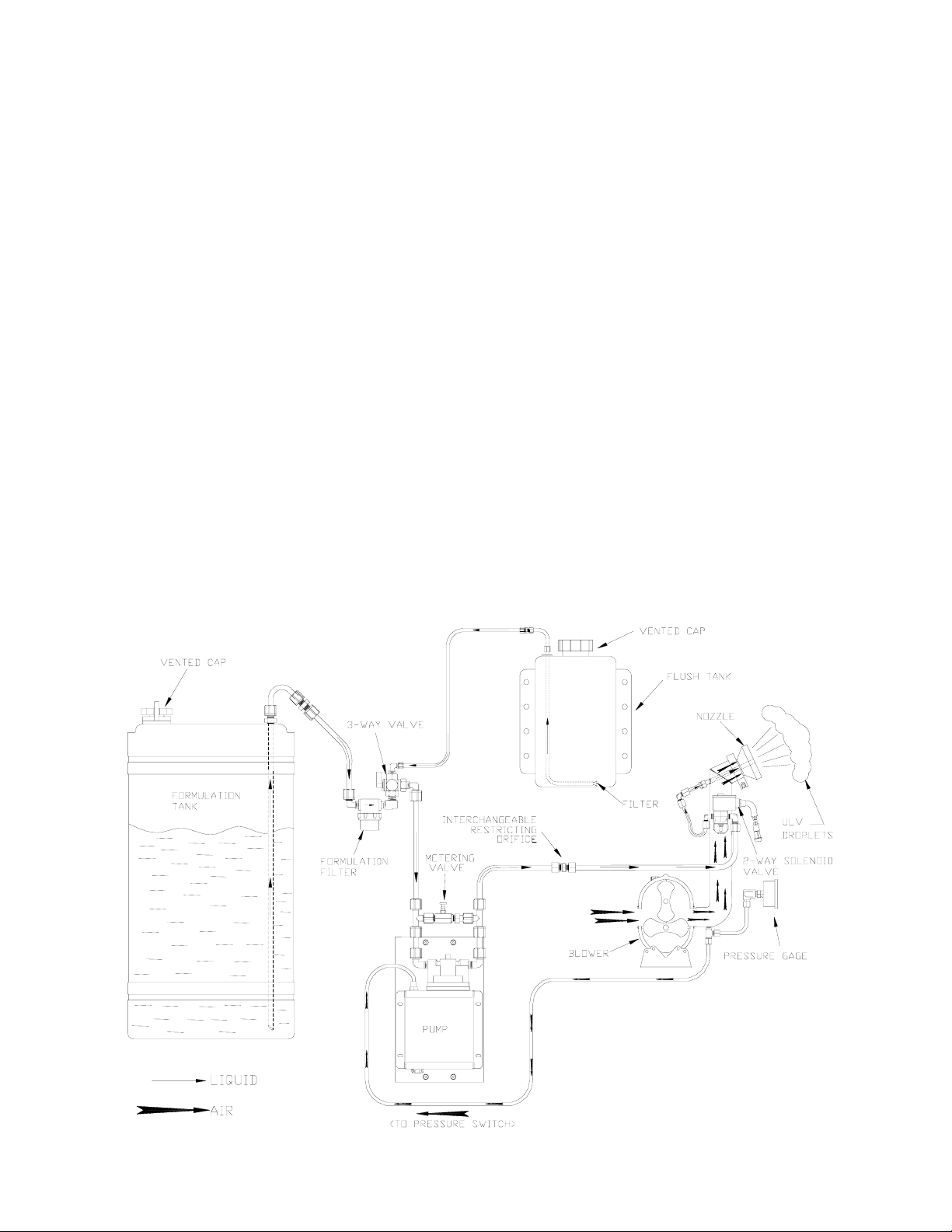
FORMULATION PUMP: Self-priming positive displacement Diaphragm Pump, Viton
elastomers, dry running capabilities, driven by a 12 VDC permanent magnet motor.
The pump head includes an internal pressure relief valve to allow the pump to
recirculate the liquid so it does not build up excess system pressure to protect the
pump. Adjustable output from 0 to 128 oz./min. (0 - 3840 ml./min).
NOZZLE SYSTEM: Boom mounted, cluster type with 360°horizontal adjustment
(azimuth) . Single nozzle.
2-WAY SOLENOID VALVE ( SHUT-OFF VALVE ): A corrosion resistant 2-way
solenoid valve is located at the Nozzle Boom assembly and is used for a positive and
instantaneous shut-off of the formulation flow. This is done by placing the SPRAY
switch located on the remote control box into either OFF (Pump stops and 2-way
valve closes) or ON position (Pump runs and 2-way valve opens).
PARTICLE SIZE: 5 - 20 Microns Volume Media Diameter (VMD) depending on flow
rate and viscosity. Bigger droplets can be obtained with higher flow rates and/or lower
boom pressure.
4

3-WAY VALVE: The manual 3-Way brass valve is used as a selector to route either
formulation or flushing solution from their respective tanks to the nozzle. The in line
formulation filter with stainless steel filtering element mesh # 80 is attached to the 3-
Way valve.
INSECTICIDE (FORMULATION) TANK: Corrosion and UV resistant, easily
removable, high density Polyethylene, with a label Formulation to avoid mistakes at
the filling operation. The tank capacity is 15 U.S. gallons (57 Lt). The tank includes a
3/8" stainless steel stand pipe and vented cap (swing style and lockable), secured to
the tank to prevent accidental loss. The formulation tank is translucent and has an
external volume scale (3 gal, 6 gal, 9 gal, 12 gal, and the top of the tank) to indicate
the formulation level.
FLUSH TANK: Corrosion and UV resistant, high density Polyethylene, with a label
FLUSH to avoid mistakes when filling. The tank capacity is 1 U.S. gallons (3.8 Lt). It
includes a vented cap, secured to the tank to prevent accidental loss. It also includes
a pick-up filter and stand pipe to deliver flush solution to the system.
REMOTE CONTROL: Machine ON/OFF, Spray ON/OFF, Engine Start. The remote
control can be removed from the machine by disconnecting an electrical quick
coupling at the end of the cable.
FRAME: High strength welded square tube frame, including cross members for
additional strength. The compact base dimensions permit easy handling and
mounting. Each machine includes four heavy duty rubber feet for even support and
higher friction coefficient with the vehicle bed. Each machine includes a heavy duty
engine/blower mounting plate with shock-absorbing pads to minimize machine
vibration.
INSTRUMENTATION: The control system is equipped with functions/switches as
indicated under Remote Control unit section. The insecticide will not flow through
lines in proximity to the operator/vehicle driver. The machine also include an air
pressure gauge (0-15 psi) glycerin filled for accuracy. The ON/OFF switch for
instantaneous shut down of the engine is located at the remote control unit (machine
switch), and on the engine itself (key switch) for safety purposes.
HI-FLEX COUPLING: To deliver the power from the engine to the blower with
maximum efficiency and reliability, the machine is equipped with a Heavy Duty direct
drive flexible coupling. The coupling, blower shaft and engine shaft are guarded for
safety.
5

FOREWORD
The application of insecticides is the predominant method by which man attempts to
control the size of insect populations. Due to environmental and economical reasons,
it is desirable to treat a given area with the least amount of insecticide that can be
made to be effective. The most efficient method is to break up the liquids into
aerosols and distribute these fine droplets over the target area. The small droplets
stay suspended for longer periods of time due to their size and are distributed more
evenly, remaining effective longer.
The term ULV is an abbreviation for Ultra-Low-Volume, the technology used to treat
areas with small amounts of chemical in an aerosol form. These chemicals are
usually in a more concentrated state than chemicals used in other methods of
application.
For best results, the Dyna-Fog ULV aerosol generator model 2992 should be
operated and maintained in compliance with this manual. Insecticides must be applied
in compliance with their label instructions.
WARNING
Read and thoroughly understand all information, cautions and warnings on the
formulation label which may affect personal safety. Know any dangers of the
solution used and know what to do in case of an accident involving the
solution.
Always use the appropriate safety equipment and dress accordingly to the
chemical formulation which is being used.
DESCRIPTION
The Dyna-Fog Mini-Pro model 2992 ULV Aerosol Generator is designed to disperse
concentrated formulations at flow rates in the range of 0 to 6.5 oz./min. (0-190 ml/min)
with droplet sizes less than 20 microns VMD (Volume-Median-Diameter). Bigger
droplets size and higher flow rates can be obtained for Barrier or Larvacide
applications.
This machine is to be vehicle, trailer or wheel kit mounted and is designed to be
operated by the driver of the vehicle using the remote control box or by an operator
close to the machine.
6

WORKING PRINCIPLES
An 8 Horsepower, four-cycle gasoline engine with a flexible coupling on its output
shaft is used to drive a positive displacement rotary-blower. The air entering the
blower is first filtered through a large stainless steel filtering element. The blower
supplies air pressure to the nozzle. The air pressure is adjustable between 2-6
PSI, 7 PSI max (0.14 – 0.41 Bar, 0.48 Bar max) by varying the engine speed
and/or by removing the air bleed orifice at the boom. The formulation is delivered
to the nozzle by means of a positive displacement diaphragm pump that draws
the formulation from the tank, through a filter and 3-way valve, and into restricting
orifice, solenoid valve and the nozzle. The nozzle has six stationary fins that
create a swirling effect of the air mass as it leaves the nozzle. In the center of this
swirling air mass is a liquid supply tube. The spray tube directs the formulation
into the air mass where it is sheared into billions of tiny droplets and dispersed
into the atmosphere.
This unit is equipped with a flushing system that is controlled from the manual 3-
way valve. The flushing liquid is conveyed to the nozzle in the same manner as
the formulation.
NOTE: The system must be flushed after each use.
MINI-PRO
FLUIDS DIAGRAM
7

8

ASSEMBLY INSTRUCTIONS
1) Uncrate the unit and remove all packing materials.
NOTE: It is a good idea to retain the original machine shipping carton for
storage.
2) Place the remote control unit where it will not be damaged while the machine
is being installed.
3) Remove the machine from the shipping skid by removing the three lag screws
that retain the shipping brackets. Keep the brackets for mounting the machine
to your Golf cart, vehicle or trailer bed.
4) Check the lubricating oil level in both the engine and blower. Refer to the
engine and blower sections of this manual and to the engine and blower
manuals for the correct filling procedure and add oil if necessary.
5) Activate the dry charge storage battery according to the following instructions:
CHARGING THE BATTERY
DANGER POISON
Batteries produce explosive gases. Keep sparks, flame and cigarettes away!
Ventilate when charging or using in an enclosed space.
The battery contains Sulfuric Acid which causes severe burns. If acid contacts eyes,
skin or clothing, flush well with water. For contact with eyes, get immediate medical
attention.
Keep battery and acid away from children and other persons who may not be aware
of dangers involved.
A. Remove battery from its mounting and place on a stable workbench.
B. Remove vent caps from battery. Remove or destroy any sealing device which
may have been used to close or restrict the vent openings in the vent caps.
C. Fill each cell of the battery to the top of the separators with approved battery
electrolyte of 1.265 specific gravity.
NOTE: The temperature of the battery and electrolyte at time of filling should
be above 60 oF (15 oC).
9

CAUTION
NEVER FILL BATTERY IN MACHINE, AS SPILLS WILL DAMAGE FINISH AND
CAUSE PREMATURE CORROSION AND / OR DAMAGE TO COMPONENTS.
D. Charge 12 volt battery at 3 - 4 amps until the acid temperature is above 80 oF
(26 oC), and the hydrometer reading is 1.250 or higher. Acid temperature must
never exceed 125 oF while charging.
NOTE: Both temperature and hydrometer readings must be met.
E. After charging the battery, check acid levels in all cells and fill each cell with
acid to the proper level.
F. Re-install vented caps.
G. Re-install the battery onto the machine in same position as it was before being
removed (terminals side of battery is facing the engine).
H. Connect the RED positive (+) cable to the positive terminal of the battery and
fasten it securely with the hardware provided.
I. Connect the BLACK negative (-) cable to the negative terminal of the battery
and fasten it securely with the hardware provided.
CAUTION
When installing the battery, connect the negative (-) cable last to
prevent sparking and shorting.
When disconnecting is required, remove the negative (-) cable
first.
Reverse polarity can cause damage to the starting and charging
system.
After battery has been initially serviced, only water should be added to restore the
liquid level in each cell. Further addition of acid will cause battery failure.
10

MACHINE INSTALLATION
1. Remove the machine from the skid and lift the machine onto the vehicle with
the discharge end of the machine toward the rear of the vehicle.
2. Pass the remote control unit through an open window (if any) and locate it
within reach of the person operating the machine. If permanent vehicle
installation is desired, the remote control cable can be fed through a clearance
hole in the vehicle chassis and then reconnected. When drilling clearance
holes, ensure that all sharp edges are removed and covered to prevent
premature wearing of the remote cable. When routing the cable to the vehicle
cab, do not allow the cable to be exposed to any sharp edges. Avoid sharp
bends when routing the cable. Once the cable has been routed to the cab,
reseal all drilled openings to prevent moisture and/or exhaust gases from
entering the cab.
3. Using the (3) hold-down brackets used for mounting the machine to the
shipping skid, securely mount the machine to the bed of the vehicle (see
diagram below). Depending on the type of bed surface, it may be necessary to
use additional mounting hardware to secure the machine.
VIEW OF MACHINE ON THE VEHICLE VIEW OF MACHINE MOUNTING BRACKET
WARNING
NEVER ATTEMPT TO OPERATE THE MACHINE WITHOUT FIRST VERIFYING
THAT IT IS SECURELY MOUNTED. FAILURE TO DO SO COULD RESULT IN
SEVERE INJURY.
11

SAFETY PRECAUTIONS
WARNING
READ AND UNDERSTAND THESE SAFETY
PRECAUTIONS BEFORE OPERATING MACHINE
1. ENGINE AND FUEL: This machine uses gasoline as the fuel for the internal
combustion engine and all precautions commonly applying to this volatile fuel
should be observed. Exercise extreme caution to avoid spilling of gasoline. If
spillage occurs, wipe it off and allow evaporation time before starting the
engine. DO NOT attempt to put fuel in tank while the machine is still running.
Avoid smoking or open flames in area when handling gasoline. Never run the
unit indoors unless exhaust is vented to outside. These fumes contain carbon
monoxide which is colorless and odorless and can be fatal.
CAUTION
DO NOT OPERATE ENGINE WITHOUT MUFFLER.
NOTE: The engine is equipped with a muffler that has spark arrestor
which is required in some States.
DO NOT TOUCH HOT MUFFLER, CYLINDERS OR FINS AS CONTACT
MAY CAUSE BURNS.
EXCEPT FOR ADJUSTMENT, DO NOT OPERATE THE ENGINE IF AIR
CLEANER OR COVER DIRECTLY OVER THE CARBURETOR AIR
INTAKE IS REMOVED.
DO NOT RUN THE UNIT IF THE COUPLING GUARD IS REMOVED.
DO NOT TAMPER WITH GOVERNOR SPRINGS, GOVERNOR LINKS
OR OTHER PARTS WHICH MAY INCREASE OR DECREASE THE
GOVERNED ENGINE SPEED.
2. MACHINE DAMAGE: Never operate a machine after it has been damaged. A
damaged machine can be very hazardous.
3. WIND: Spraying during windy conditions is not usually practical because the
formulation will drift out of the intended area. However, under NO
circumstances should spraying into the wind be attempted. This may cause
hazardous accumulations on the machine or carrying vehicle.
12

4. SAFETY EQUIPMENT: In addition to any safety equipment that may be
required by the type of formulation which is being used, the following items
should be mandatory for each vehicle which carries this machine during
fogging operations.
a. Fire Extinguisher, chemical-type rated for fuel fires.
b. First Aid Kit.
c. Eye Wash Solution.
d. Safety Glasses.
e. Container of Oil Dry Compound.
f. Gloves Rated for High Temperature.
g. Respirator Adequate for Formulation being used.
5. CHILDREN: Many spraying operations are performed in residential areas,
commonly at dusk. This presents the operator with the problem of children
who are attracted to the noise and/or mist being created. Children have been
observed running into and riding bicycles through the mist. The possible
hazard lies in the toxic effect of some formulations, the severity of which
depends upon the chemical used, mist density and the length of time of direct
exposure.
IT IS THE OPERATOR'S RESPONSIBILITY TO DISCOURAGE ANYONE
FROM PLAYING IN THE MIST OR BEING NEAR THE MOVING VEHICLE.
6. FORMULATIONS: Ensure that formulations are applied only in strict
compliance with the formulation label as well as local, state and federal
regulations and that these formulations are dispersed only by trained
personnel of public health organizations, mosquito abatement districts, pest
control operators or other qualified personnel.
a. Always comply with any requirements for protective clothing, goggles,
gloves, facial masks or respirators required on the formulation label.
b. Do not exceed the dosage set forth on the registration label of the
insecticide to be used.
c. Always store formulation in its original labeled container.
7. BLOWER PRESSURE: Do not allow to operate with blower pressure above 6
psi, and never under any circumstance exceed 7 psi. For most applications, a
blower pressure (nozzle pressure) of 6 psi is satisfactory.
13

MACHINE OPERATION
CAUTION
READ THIS COMPLETE OPERATION SECTION AND THE SECTION ON SAFETY
PRECAUTIONS BEFORE STARTING THE MACHINE FOR THE FIRST TIME.
For first time operation, the sections on MACHINE INSTALLATION and MACHNE
OPERATION must be performed before proceeding with this section.
When operating this machine for the first time, move to an uncongested and well-
vented work area away from flammable materials.
WARNING
READ THE SECTION ON SAFETY PRECAUTIONS BEFORE PREPARING TO
DISPENSE FORMULATION.
READ AND THOROUGHLY UNDERSTAND ALL INFORMATION, CAUTIONS AND
WARNINGS ON THE FORMULATION LABEL WHICH MAY AFFECT PERSONAL
SAFETY. KNOW ANY DANGERS OF THE SOLUTION USED AND KNOW WHAT
TO DO IN CASE OF AN ACCIDENT INVOLVING THE SOLUTION.
ALWAYS USE THE APPROPRIATE SAFETY EQUIPMENT AND DRESS
ACCORDING TO THE CHEMICAL FORMULATION WHICH IS BEING USED.
WARNING
DO NOT USE ANY SUBSTANCES FROM UNMARKED CONTAINERS OR FROM
CONTAINERS WITH OBVIOUSLY ALTERED LABELS.
READ AND FOLLOW THE INSTRUCTIONS ON THE CHEMICAL SOLUTION LABEL
FOR ULV SPRAYING OF THE SOLUTION.
DO NOT SPRAY NEAR AN OPEN FLAME OR HOT MATERIALS.
DO NOT LEAVE THE MACHINE UNATTENDED.
14

PRE-SPRAY CHECK LIST
1. Verify that the remote control box is within easy reach of the operator.
2. Verify that the boom is in the correct position as required for the spraying
operation to be accomplished, and that the ring clamp which allows this
positioning is tight.
3. Verify that the engine has sufficient fuel and is properly lubricated.
4. Verify that the blower has been serviced.
5. Inspect all hoses for abnormal conditions.
6. Verify that no foreign objects or tools have been left in or about the machine.
7. Verify that the sufficient amount of formulation is in the tank and that the tank
filling cap is tight and its air vent hole is not restricted.
8. Verify that the battery is mounted securely and cable connections are proper
and tight.
9. Verify that all safety equipment is in place and is in proper working order.
10. Verify that the flow rate control has been calibrated and is dispensing
formulation in accordance with the manufacturers label requirements.
CAUTION
BEFORE PROCEEDING WITH ANY SPRAYING OPERATION, THE OPERATOR
SHOULD BE THOROUGHLY FAMILIAR WITH STARTING AND STOPPING THE
MACHINE AND WITH ALL THE OPERATING CONTROLS. IF YOU ARE
OPERATING THE MACHINE FOR THE FIRST TIME, EXERCISE THE MACHINE
THROUGH ITS FULL OPERATIONAL SEQUENCES FROM A POSITION OF FULL
VISIBILITY OF THE MACHINE BEFORE OPERATING THE MACHINE FULLY
REMOTE. THIS IS ALSO A GOOD IDEA FOR EXPERIENCED OPERATORS WHO
MAY BE OPERATING A NEW MACHINE OR WHO MAY BE REACTIVATING A
MACHINE AFTER REPAIRS OR A PERIOD OF INACTIVITY. REFER TO THE
ENGINE MANUAL FOR STARTING AND STOPPING INSTRUCTIONS.
15

ENGINE PREPARATION
Oil Recommendations
Change and add oil according to chart below. Do not overfill. Use high quality
detergent oil API classified “For service SC, SD, SE, SF, SG”. If oil remains in the
engine, oil viscosity must be suitable for the lowest temperature at which the engine will
be operated in service. Use no special additives with recommended oils.
(*) Air-cooled engines run
hotter than automotive
engines. Use of multi-
viscosity oils (10W-30,
etc.) above 40°F (4°C) will
result in high oil
consumption and possible
engine damage. Check oil
level more frequently if
using these types of oil.
(**) SAE 30 oil, if used
below 40 °F (4 °C), will
result in hard starting and possible engine bore damage due to inadequate lubrication.
Check oil level before starting engine. Add oil (if required).
Start and run the engine at idle for 30 seconds. Shut engine off. Wait 30 seconds and
check oil level. Add oil to bring level to Full mark on dipstick, if required.
NOTE: Engine is shipped from factory without oil. Before starting the engine, check oil
level.
Fuel Recommendations
The engine will operate satisfactorily using any automobile gasoline. Use clean, fresh,
lead-free gasoline with a minimum of 85 octane for overhead valve engines. Leaded
gasoline may be used if it is commercially available, and if lead-free is not available.
Use of lead-free gasoline results in fewer combustion deposits and longer valve life.
Purchase fuel in quantity that can be used within 30 days. This will assure fuel
freshness and volatility tailored to the season. DO NOT MIX OIL WITH GASOLINE.
B&S does not recommend using gasoline which contains alcohol, such a gasohol. If
gasoline with alcohol is used, it must contain less than 10% Ethanol and must be
removed from engine during storage. Do not use gasoline which contains Methanol.
Fuel Level: Do not overfill. Allow space in fuel tank for fuel expansion.
16

STARTING THE ENGINE
CHOKE ENGINE: Move engine choke control to position lever in "choke" position
(pulling the control rod).
NOTE: This should fully close choke on carburetor.
NOTE: The manual choke is provided for cold starting of the engine. Once the engine
has been allowed to warm-up, choking the engine should not be needed for restarting.
TURN “ON” THE MACHINE “ON/OFF” SWITCH: Position Machine “ON/OFF” s itch
on the remote control box to "ON” position. Also verify that the “SPRAY” s itch on the
remote control box is in the “OFF” position.
TURN "ON" (RUN) THE KEY SWITCH: Position key s itch on engine to "ON”. This
s itch is located next to the starter button. Also turn ON the fuel valve.
START ENGINE: Activate the spring-loaded starter s itch on the engine or activate the
rocker s itch on the remote control box to the start position.
NOTE: To prevent overheating the engine starter motor, do not activate the motor
longer than 15 seconds at a time.
SET ENGINE SPEED: Allo the engine to arm-up and gradually move the choke
lever to the RUN (unchoked) position.
Adjust the engine Speed control to achieve the desired Boom Pressure. Increase the
engine speed to increase the boom pressure.
17
CHOKE
CONTROL
FUEL
VALVE
SPEED
CONTROL
START
SWITCH
REMOTE
CONTROL
MACHINE
SWITCH

BLOWER LUBRICATION – MINI-PRO
A simple but very effective lubrication system is employed on UNIVERSAL RAI blowers. At the
drive shaft end the bearings are grease lubricated using hydraulic pressure relief fittings. These
relief fittings vent any excess grease, preventing pressure build-up on the seals. A restriction plug
and metering orifice prevent loss of lubricant from initial surges in lubricant pressure but permit
venting excess lubricant under steadily rising pressures.
The blind end bearings and timing gears are enclosed by a gearhouse located opposite the drive
end of the blower. In a side outlet blower, the lower timing gear functions as an oil slinger,
carrying lubricant to the upper timing gear and providing splash lubrication for the bearings.
Pressure within the gearbox is vented through the breather vent plug.
Before starting blower, be sure oil has been put in gearhouse. For recommended lubrication oil
see Table below. Use a good grade industrial type rust, oxidation, and foam inhibited, non-
detergent oil such as Mobil DTE BB, Texaco R&O 220,Amoco 220 or equal. Also, Roots synthetic
oil has proven to be an excellent lubricant.
Recommended Oil Grades (Gear Oil)
Ambient Viscosity Range ISO No Approximate
Temperature °F (°C) SSU at 100° F(38 °C) SAE No
Above 90° (32°C) 1000-1200 320 60
32° to 90° (0° to 32°) 700-1000 220 50
0° to 32° (-18° to 0°) 500-700 150 40
Below 0° (-18°) 300-500 100 30
To fill the gearbox, remove the breather plug and the oil overflow plug (see diagram). Fill the
reservoir up to the overflow hole. Place the breather and the overflow plug back into their
respective holes.
Frame Size 24: Capacity, 3.4 Oz. (.1 Liters)
Proper lubrication is usually the most important single consideration in obtaining maximum
service life and the most satisfactory operation from the unit. Unless operating conditions are
quite severe, a weekly check of gearhouse oil level and necessary addition of lubricant should be
sufficient. However, oil should be changed after initial 100 hours
Of operation. Thereafter, a complete oil change normally is made after 1000 operating hours, or
less, depending on the type oil and oil operating temperature.
Shaftbearings at the driveend of the blower are grease lubricated and each
bearing housing is equipped with pressure type grease fittings and pressure type relief fittings.
When servicing drive end bearings, use a NLGI #2 premium grade, petroleum base grease with
high temperature (300° service temperature) and moisture resistance and good mechanical
stability. Using a pressure gun, force new lubricant into each drive end bearing housing until
traces of clean grease comes out of the relief fitting.
After a long shutdown, it is recommended that the grease relief fittings be removed, the
old grease flushed out with kerosene or #10 lubricating oil, drained thoroughly, and bearings
refilled with new grease. Be sure grease relief fittings are reinstalled. Grease should be added
using hand operated grease gun to the drive end bearings at varying time intervals depending on
duty cycle and RPM. Information has been prepared as a general greasing schedule guide based
on average operating conditions. More frequent intervals may be necessary depending on the
grease operating temperature and under unusual circumstances.
Suggested Bearing Lubrication Intervals
Speed Operating Hours Day
In 8 16 24
RPM Greasing Intervals in Weeks
1500-2000 4 2 1
2000-2500 3 1 1
2500-3000 2 1 1
18

MEASURING LIQUID FLOWABILITY (VISCOSITY)
In order to achieve consistent results in generating aerosols with a mass median
diameter (MMD) in the sub 20-micron range, several variables must be kept under
control at the same time. The ability of an aerosol generator to consistently break up
a liquid into appropriate sized droplets depends on (3) key elements:
1. The available energy flow (air flow) through the nozzle is governed by the
blower speed. As the air mass and its velocity through the nozzle decreases,
the droplet size (MMD) will increase assuming that the liquids viscosity and
flow rate remains constant.
2. The flow rate of the liquid governed by the speed of the liquid pump.
3. The viscosity of the liquid.
Various liquids have different viscosities. Viscosity is defined as a fluids resistance to
flow commonly measured in units of a centipoise (CP). Generally, the thicker the
liquid, the greater the viscosity and the higher the CP number. Examples of some
liquid viscosities are:
LIQUID VISCOSITY (CP)
WATER 1
DIBROM 3-4
DOW MFC 3-4
PYRETHRIN, RESMETHRIN 6-7
DURSBAN 1.5 ULV 12-14
TECHNICAL MALATHION 28
By measuring the flowability of a liquid, adjusting the engine speed to produce the
desired nozzle boom pressure, and by setting the flow rate, accurate particle size can
be achieved.
To measure the relative flowability (viscosity) of your formulation:
19
1. Place a sample of the formulation liquid to
be dispensed in the relative flowability
meter provided with the machine such that
the liquid level is above the top line.
2. Hold the meter vertical and allow the liquid
to flow through the brass orifice at the
outlet end of the meter into an appropriate
container.

3. Using a stopwatch or a watch with a sweep second hand, determine the
flowability time in seconds that it takes for the liquid level to fall from the top
line to the bottom line.
Once the flowability of the liquid has been measured, tables on next page can be
used as an approximate guide for setting the pump flow rate and nozzle boom
pressure for your spray application, taking into account the expected Droplet size.
NOTE: Periodically calibrate the flowability meter using plain water. Water should
flow through the orifice such that the time between the top line and the bottom line is
32 + 2 seconds.
CAUTION
Follow all warnings and cautions on your formulation label. Do not attempt to apply
any formulation at a rate greater than what is specified on the formulation label. This
includes driving your vehicle at a rate slower than what is specified.
CAUTION
The rates on the next page are examples of typical application rates found on their
respective formulation labels. Refer to the label of your formulation to determine the
actual application rate before calibrating your machine to any of the above flow rates.
Once the flowability of the formulation to be sprayed has been determined and the
formulation pump has been calibrated select one of the tables (next page) that is
closest to the flowability of the formulation to be sprayed. Then match the closest
flow rate in the left hand column with the flow rate specified on the formulation label. A
boom pressure can then be selected that will produce a particle size in accordance
with the formulation label. Remember, with a constant flow rate supplied to the nozzle
system, increasing nozzle boom pressure will decrease particle size.
20
This manual suits for next models
1
Table of contents
Other Curtis Water Pump manuals
Popular Water Pump manuals by other brands

SFA
SFA SFA SANISPEED quick start guide

HP
HP 5660-97 Specifications information and repair parts manual

Craco
Craco Fire-Ball 425 Instructions-parts list

MP PUMPS
MP PUMPS FLOMAX 8 Operator's manual

The Fountainhead Group
The Fountainhead Group Smith Indian Fire Pump use and care manual

Lutz-Jesco
Lutz-Jesco MEMDOS SMART LD operating instructions

Mäktig
Mäktig 601625 instruction manual

DeatschWerks
DeatschWerks Mustang DW400 installation guide

Q-MAX
Q-MAX MAX-FLO MY1-06 NON-METAL Series Assembly, installation and operation manual

JABSCO
JABSCO 31295-0092 user manual

VERDER
VERDER HI-CLEAN VA-2H40 repair parts

Rheinstrom
Rheinstrom M 50 E Installation operation & maintenance