Cushman HAULER PRO 2014 User manual

TECHNICIAN’S REPAIR AND SERVICE MANUAL
72V Electric Powered Utility Vehicle
634756
ISSUED MAY 2014

NOTICES, CAUTIONS AND WARNINGS CONTINUED ON INSIDE OF BACK COVER.
SAFETY
For any questions on material contained in this manual, contact an authorized representative for clarification.
Read and understand all labels located on the vehicle. Always replace any damaged or missing labels.
On steep hills, vehicles may coast at faster speeds than those encountered on a flat surface. To prevent loss of vehicle control and pos-
sible injury, speeds should be limited to no more than the maximum level ground speed indicated in GENERAL SPECIFICATIONS. Limit
speed by applying the service brake.
Catastrophic damage to drivetrain components due to excessive speed may result from driving the vehicle above specified speed. Dam-
age caused by excessive speed may cause a loss of vehicle control, is considered abuse and will not be covered under warranty.
For towing/transporting vehicle, refer to TRANSPORTING VEHICLE section.
If the vehicle is to be used in a commercial environment, signs similar to the ones illustrated should be used to warn of situations that
could result in an unsafe condition.
NOTICES, CAUTIONS, WARNINGS
AND DANGERS
Observe the NOTICES, CAUTIONS, WARNINGS, and DAN-
GERS; be aware that servicing a vehicle requires mechanical
skill and a regard for conditions that could be hazardous.
Improper service or repair may damage the vehicle or render it
unsafe for use.
Address practices not related to personal injury.
Indicates a hazardous situation which, if not avoided,
could result in minor or moderate injury.
Indicates a hazardous situation which, if not
avoided, could result in death or serious injury.
Indicates a hazardous situation which, if not
avoided, will result in death or serious
injury.
Battery posts, terminals and related accessories
contain lead and lead compounds. Wash hands
after handling.

Never modify the vehicle in any way that will alter the weight distribution of the vehicle, decrease its stability or increase the speed
beyond the factory specifications. Such modifications can cause serious personal injury or death. E-Z-GO Division of Textron Inc. prohib-
its and disclaims responsibility for any such modifications or any other alteration which would adversely affect the safety of the vehicle.
E-Z-GO Division of Textron Inc. reserves the right to incorporate engineering and design changes to products in this manual, without obli-
gation to include these changes on units sold previously.
The information contained in this manual may be revised periodically by E-Z-GO, and therefore is subject to change without notice.
E-Z-GO DISCLAIMS LIABILITY FOR ERRORS IN THIS MANUAL, and SPECIFICALLY DISCLAIMS LIABILITY FOR INCIDENTAL AND CONSE-
QUENTIAL DAMAGES resulting from the use of the information and materials in this Manual.
These are the original instructions as defined by 2006/42/EC.
CONTACT US:
E-Z-GO Division of Textron Inc.
1451 Marvin Griffin Road.
Augusta, Georgia, USA 30906-3852
North America:
Technical Assistance & Warranty PHONE: 1-800-774-3946 FAX: 1-800-448-8124
Service Parts PHONE: 1-888-GET-EZGO (1-888-438-3946) FAX: 1-800-752-6175
International:
PHONE: 001-706-798-4311 FAX: 001-706-771-4609
i
Repair and Service Manual
634756
REPAIR AND SERVICE MANUAL
72V ELECTRIC UTILITY VEHICLE
HAULER PRO
STARTING MODEL YEAR 2014
CALIFORNIA Proposition 65 Warning
WARNING: Engine exhaust, some of its constituents, and certain vehicle components contain or emit chemicals known
to the State of California to cause cancer and brith defects or other reproductive harm. In addition, certain fluids con-
tained in vehicles and certain products of component wear contain or emit chemicals known to the State of California to
cause cancer and birth defects or other reproductive harm.

GENERAL INFORMATION
ii Repair and Service Manual 634756
This vehicle has been designed and manufactured in the United States of America (USA).
The Standards and Specifications listed in the following text originate in the USA unless oth-
erwise indicated.
The use of non-Original Equipment Manufacturer (OEM) approved parts may void the
warranty.
Overfilling battery may void the warranty.
Tampering with or adjusting the governor to permit vehicle to operate at above factory spec-
ifications will void the vehicle warranty.
When servicing engines, all adjustments and replacement components must be per original
vehicle specifications in order to maintain the United States of America Federal and State
emission certification applicable at the time of manufacture.
BATTERY PROLONGED STORAGE
Batteries self-discharge over time. The rate of self-discharge varies depending on the ambi-
ent temperature, the age and condition of the batteries.
Fully charged batteries will not freeze in winter temperatures unless the temperature falls
below -75°F (- 60°C).
BATTERY DISPOSAL
Lead-acid batteries are recyclable. Return whole scrap batteries to distributor, manufacturer
or lead smelter for recycling. For neutralized spills, place residue in acid-resistant contain-
ers with absorbent material, sand or earth and dispose of in accordance with local, state and
federal regulations for acid and lead compounds. Contact local and/or state environmental
officials regarding disposal information.

iii
Repair and Service Manual
SAFETY INFORMATION
634756
SAFETY INFORMATION
This manual has been designed to assist the owner-operator in maintaining the vehicle in accordance with procedures
developed by the manufacturer. Adherence to these procedures and troubleshooting tips will ensure the best possible
service from the product. To reduce the chance of personal injury and/or property damage, the following instructions
must be carefully observed:
GENERAL
Many vehicles are used for a variety of tasks beyond their original intended use; therefore it is impossible to anticipate
and warn against every possible combination of circumstances that may occur. Warnings cannot replace good common
sense and prudent driving practices. Common sense and prudent driving practices do more to prevent accidents and
injury than warnings and instructions can provide.
The manufacturer strongly suggests anyone operating the vehicle read the entire owner’s guide provided with the pur-
chase of the vehicle, paying particular attention to the CAUTIONS, WARNINGS and DANGERS within.
For any questions or concerns, contact the closest representative, or write to the address on the back cover of this pub-
lication, Attention: Customer Care Department.
E-Z-GO Division of Textron reserves the right to make design changes without obligation to make these changes on
units previously sold and the information contained in this manual is subject to change without notice.
E-Z-GO Division of Textron is not liable for errors in this manual or for incidental or consequential damages that result
from the use of the material in this manual.
This vehicle conforms to the current applicable standard for safety and performance requirements.
This vehicle is designed and manufactured for off-road use. It does not conform to Federal Motor Vehicle Safety Stan-
dards and is not equipped for operation on public streets. Some communities may permit these types of vehicles to be
operated on their streets on a limited basis and in accordance with local ordinances.
Ensure all electrical accessories are grounded to the DC to DC converter negative (-); not to the battery (-) post. Never
use the chassis or body as a ground connection.
Refer to GENERAL SPECIFICATIONS for vehicle seating capacity. Do not exceed number of occupants indicated.
Never modify the vehicle in any way that will alter the weight distribution of the vehicle, decrease
it’s stability, increase the speed or extend the stopping distance beyond the factory specification.
Such modifications can result in serious personal injury or death.
Modifications that increase the speed and/or weight of the vehicle will extend the braking distance and may reduce the
stability of the vehicle. Do not make any such modifications or changes. The manufacturer prohibits and disclaims
responsibility for any such modifications or any other alteration which would adversely affect the safety of the vehicle.
Speed should be moderated by the environmental conditions, terrain and common sense.
GENERAL OPERATION
ALWAYS:
• Use the vehicle in a responsible manner and maintain the vehicle in safe operating condition.
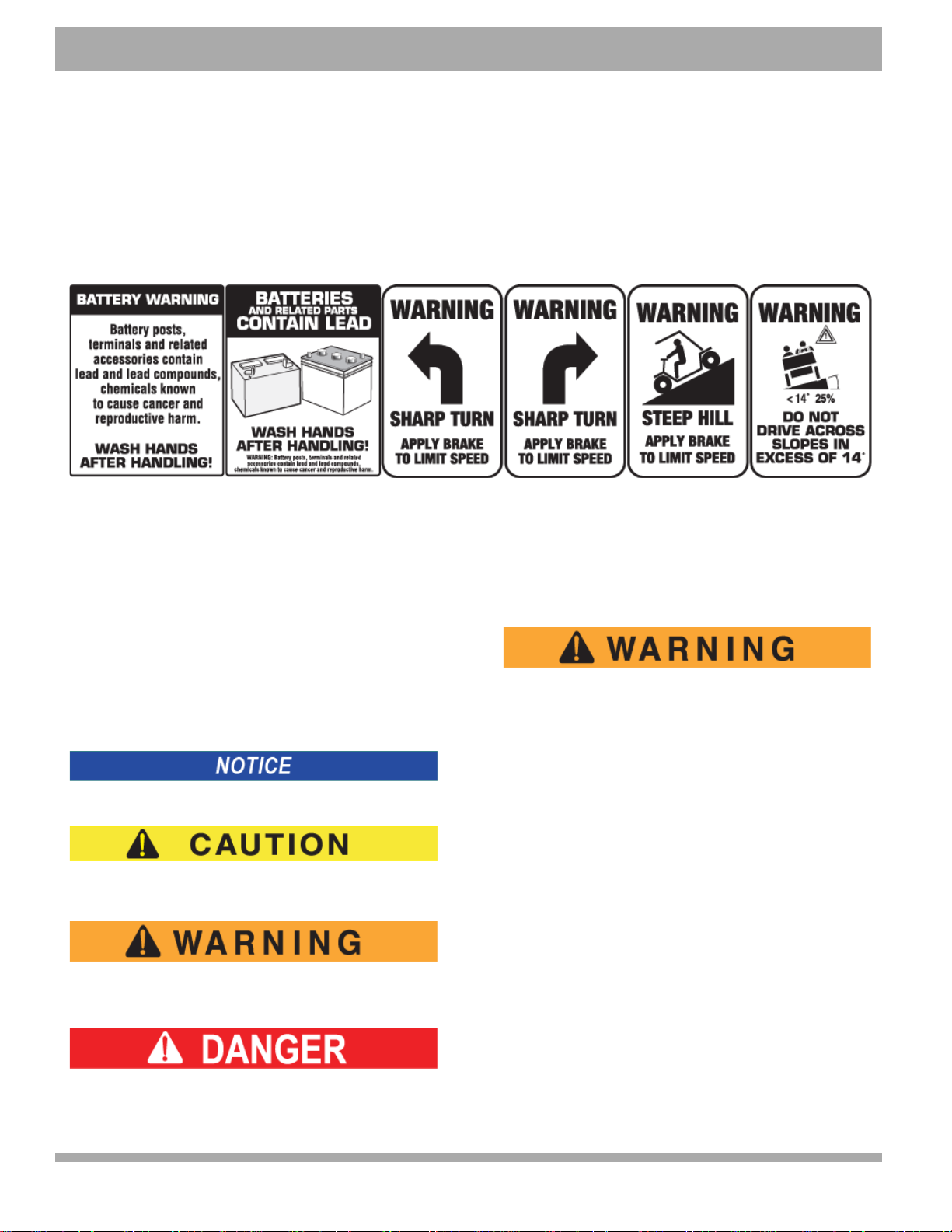
• Read and observe all warnings and operation instruction labels affixed to the vehicle.
• Follow all safety rules established in the area where the vehicle is being operated.
• Reduce speed to compensate for poor terrain or conditions.
• Apply service brake to control speed on steep grades.
• Reduce speed in damp or wet areas.
• Use caution when approaching sharp or blind turns.
• Use caution when driving over loose terrain.
• Use caution when driving in areas where pedestrians are present.

iv Repair and Service Manual
SAFETY INFORMATION
634756
MAINTENANCE
ALWAYS:
• Replace damaged or missing warning, caution or information labels.
• Maintain the vehicle in accordance with the manufacturer’s periodic service schedule.
• Ensure that repairs are performed by trained and qualified persons.
• Follow the manufacturer’s maintenance procedures.
• Insulate any tools used within the battery area in order to prevent sparks or battery explosion.
• Check the polarity of each battery terminal and be sure to rewire the batteries correctly.
• Use specified replacement parts. Never use replacement parts of lesser quality.
• Use recommended tools.
• Determine that tools and procedures not specifically recommended by the manufacturer will not compromise the
safety of personnel, nor jeopardize the safe operation of the vehicle.
• Support the vehicle using wheel chocks and safety stands. Never get under a vehicle that is supported by a jack.
Lift the vehicle in accordance with the manufacturer’s instructions.
• Never attempt to maintain a vehicle in an area where exposed flame is present or persons are smoking.
• Be aware that a vehicle that is not performing as designed is a potential hazard and must not be operated.
• Test drive vehicle after repairs or maintenance in a safe area free of vehicular and pedestrian traffic.
• Keep complete records of the maintenance history of the vehicle.
VENTILATION
ALWAYS:
• Charge vehicle in a well ventilated area.
• Charge in an area free of flammable liquids and items.
• Charge a vehicle in an area that is free from flame or spark. Pay particular attention to natural gas or propane
gas water heaters and furnaces.
• Use a dedicated circuit for battery charger. Do not permit other appliances to be plugged into the receptacle
when the charger is in operation.
• Operate charger in accordance with manufacturers recommendations or applicable electrical code.

B
TABLE OF CONTENTS
v
Repair and Service Manual
634756
SAFETY INFORMATION
GENERAL ........................................................................................................................ III
GENERAL OPERATION.................................................................................................. III
MAINTENANCE ............................................................................................................... IV
VENTILATION.................................................................................................................. IV
GENERAL INFORMATION AND ROUTINE MAINTENANCE
SERIAL NUMBER LABEL LOCATION ............................................................................. 1
TRANSPORTING VEHICLE ............................................................................................. 1
Towing .................................................................................................................. 1
Hauling ................................................................................................................. 1
SERVICING THE ELECTRIC VEHICLE ........................................................................... 1
ROUTINE MAINTENANCE............................................................................................... 2
REAR AXLE ...................................................................................................................... 2
BRAKES............................................................................................................................ 2
TIRES................................................................................................................................ 2
Recommended Tire Pressures ............................................................................ 2
LIGHT BULB REPLACEMENT ......................................................................................... 2
VEHICLE CLEANING AND CARE.................................................................................... 3
VEHICLE CARE PRODUCTS........................................................................................... 3
SUN TOP AND WINDSHIELD .......................................................................................... 3
HARDWARE ..................................................................................................................... 4
SAFETY
NOTICES, CAUTIONS, WARNINGS AND DANGERS .................................................... 5
IMPORTANT SAFETY WARNING.................................................................................... 5
MODIFICATIONS TO VEHICLE ....................................................................................... 5
GENERAL MAINTENANCE.............................................................................................. 5
BEFORE SERVICING THE VEHICLE .............................................................................. 6
Additional Warnings Specific to Electrical System ............................................... 6
BATTERY REMOVAL AND INSTALLATION.................................................................... 7
LIFTING THE VEHICLE.................................................................................................... 8
BODY
GENERAL ....................................................................................................................... 11
BODY COMPONENT REPLACEMENT.......................................................................... 11
Instrument Panel Replacement .......................................................................... 12

B
vi Repair and Service Manual
TABLE OF CONTENTS
634756
Center Compartment Replacement ....................................................................13
Cowl Replacement ..............................................................................................13
Brush Guard Replacement .................................................................................13
Rocker Panel Replacement ................................................................................14
Side Panel Replacement ....................................................................................14
Rear Fender Replacement ..................................................................................14
Rear Body Panel Replacement ...........................................................................15
PAINTING ........................................................................................................................ 16
Minor Scratches ..................................................................................................16
Larger Scratches .................................................................................................16
Complete Panel Repair .......................................................................................16
WHEELS AND TIRES
WHEEL AND TIRE SERVICE.......................................................................................... 17
Tire Repair ..........................................................................................................17
Wheel Installation ................................................................................................18
FRONT SUSPENSION AND STEERING
MAINTENANCE............................................................................................................... 20
Lubrication ..........................................................................................................20
Wheel Bearing and King Pin Bushing Inspection ................................................20
Wheel Bearing Packing .......................................................................................20
Wheel Bearing Adjustment .................................................................................21
Wheel Alignment .................................................................................................21
FRONT SUSPENSION .................................................................................................... 23
Front Shock Absorber Replacement ...................................................................24
Front Axle Replacement .....................................................................................24
Axle Linkage Rod Replacement ..........................................................................24
Front Spring Replacement ..................................................................................25
Hub Replacement ...............................................................................................26
Wheel Bearing and Race Replacement ..............................................................27
STEERING....................................................................................................................... 28
Rack Ball Joint Replacement ..............................................................................28
Tie Rod Inspection/Replacement ........................................................................29
Bellows Replacement .........................................................................................30
Pinion Seal Replacement ....................................................................................30
Spindle Replacement ..........................................................................................31

B
TABLE OF CONTENTS
vii
Repair and Service Manual
634756
Rack and Pinion Unit Disassembly and Inspection ............................................ 32
Rack and Pinion Unit Replacement ................................................................... 33
Checking/Adjusting Rack Extension-to-Rack and Pinion Unit Clearance .......... 33
Steering Wheel Replacement ............................................................................ 34
Steering Shaft and Column Replacement .......................................................... 35
ELECTRONIC SPEED CONTROL
SPEED SENSOR............................................................................................................ 39
CONTROLLER................................................................................................................ 39
CONTROLLER REPLACEMENT.................................................................................... 39
SOLENOID REPLACEMENT.......................................................................................... 40
MOTOR
GENERAL ....................................................................................................................... 43
Motor Replacement ............................................................................................ 43
Motor Tests ........................................................................................................ 44
BATTERIES AND CHARGING
SAFETY .......................................................................................................................... 45
BATTERY........................................................................................................................ 45
BATTERY MAINTENANCE ............................................................................................ 46
At Each Charging Cycle ..................................................................................... 46
Monthly ............................................................................................................... 46
Electrolyte Level and Water ............................................................................... 46
Cleaning Batteries .............................................................................................. 47
Battery Replacement .......................................................................................... 48
Prolonged Storage ............................................................................................. 48
Battery Charging ................................................................................................ 49
AC Voltage ......................................................................................................... 49
FAULT DIAGNOSIS........................................................................................................ 49
Hydrometer ........................................................................................................ 50
Using A Hydrometer ........................................................................................... 50
ELECTRICAL SYSTEM
AWG TO METRIC CONVERSIONS ............................................................................... 56
VOLTAGE TEST FOR BATTERIES ............................................................................... 56
MAIN HARNESS............................................................................................................. 56
Power Supply ..................................................................................................... 56

B
viii Repair and Service Manual
TABLE OF CONTENTS
634756
Accessory Wiring ................................................................................................58
Faulty Wire Replacement ....................................................................................58
Headlight Replacement .......................................................................................58
Taillight Replacement .........................................................................................59
FAULT DIAGNOSIS......................................................................................................... 60
General ...............................................................................................................60
Testing Battery Voltage .......................................................................................60
Continuity Check .................................................................................................60
Testing a Switch for Continuity ...........................................................................61
Testing a Solenoid for Continuity ........................................................................61
BRAKES
BRAKE SYSTEM OVERVIEW......................................................................................... 65
General Description ............................................................................................65
How the Service Brake Works ............................................................................65
Equalizer Link .....................................................................................................66
Automatic Adjuster Mechanism ..........................................................................66
How the Park Brake Works .................................................................................66
Kick-Off Actuating Linkage ..................................................................................66
Compensator Assembly ......................................................................................66
FAULT DIAGNOSIS FLOWCHART................................................................................. 67
FAULT DIAGNOSIS TABLE ............................................................................................ 69
FAULT DIAGNOSIS AND INSPECTION ......................................................................... 70
New Vehicle ........................................................................................................70
Fault Diagnosis and Inspection Procedures .......................................................70
Brake Pedal and Linkage Inspection ..................................................................71
Periodic Brake Performance Test (PBPT) ..........................................................73
Aggressive Stop Test ..........................................................................................74
Wheel Brake Inspection ......................................................................................74
MAINTENANCE AND REPAIRS ..................................................................................... 76
Adjusting Brake Pedal Free Travel .....................................................................77
Brake Drum Removal and Installation ................................................................78
Wheel Brake Service ..........................................................................................78
Backing Plate/Entire Wheel Brake Assembly Removal and Installation .............79
Brake Shoe Removal ..........................................................................................80
Brake Shoe Installation .......................................................................................81

B
TABLE OF CONTENTS
ix
Repair and Service Manual
634756
Brake Cable and Equalizer Assembly Removal and Installation ....................... 82
Compensator Assembly, Removal and Installation ............................................ 82
Brake Pedal Removal and Installation ............................................................... 82
Park Brake Catch Bracket Removal and Installation ......................................... 83
Park Brake Pedal Removal and Installation ....................................................... 83
Pedal Bumper Adjustment ................................................................................. 83
Park Brake Release Linkage Removal and Replacement ................................. 84
Park Brake Kick-Off Cam Removal, Replacement and Installation ................... 84
OPTIONAL FRONT HYDRAULIC BRAKES
SYSTEM DESCRIPTION................................................................................................ 85
MASTER CYLINDER REPLACEMENT .......................................................................... 85
Remove Master Cylinder .................................................................................... 85
Install Master Cylinder ........................................................................................ 85
BRAKE MASTER CYLINDER FLUID ............................................................................. 86
Flush Hydraulic Brake System ........................................................................... 86
Check Brake Fluid .............................................................................................. 86
ROUTINE MAINTENANCE............................................................................................. 86
REPLACEMENT OF WEAR ITEMS ............................................................................... 86
Brake Pad Replacement .................................................................................... 86
Rotor Replacement ............................................................................................ 87
Spindle Replacement ......................................................................................... 87
Actuator Linkage Bushings ................................................................................ 87
Actuator Pivot Bushings ..................................................................................... 87
BLEEDING BRAKES ...................................................................................................... 87
General Information about Bleeding Brakes ...................................................... 87
Brake Bleeding Procedure ................................................................................. 88
BATTERY CHARGER
CHARGER DESCRIPTION............................................................................................. 89
PORTABLE CHARGER OPTION ................................................................................... 89
REAR SUSPENSION
REAR SUSPENSION...................................................................................................... 91
General .............................................................................................................. 91
Shock Absorber Removal .................................................................................. 91
Shock Absorber Installation ............................................................................... 91

B
xRepair and Service Manual
TABLE OF CONTENTS
634756
Rear Spring Removal ..........................................................................................91
Rear Spring Installation .......................................................................................92
Rear Axle Assembly Removal ............................................................................92
Rear Axle Assembly Installation .........................................................................92
REAR AXLE
REAR AXLE MAINTENANCE.......................................................................................... 95
Checking the Lubricant Level ..............................................................................95
REAR AXLE DISASSEMBLY .......................................................................................... 95
Axle Shaft Removal and Disassembly ................................................................95
Axle Shaft Seal Removal and Replacement .......................................................96
Axle Shaft Replacement .....................................................................................97
WEATHER PROTECTION
SUN TOP AND WINDSHIELD....................................................................................... 101
Transporting Vehicle .........................................................................................101
SUN TOP....................................................................................................................... 101
Rear Support Installation ..................................................................................101
Front Struts .......................................................................................................101
Sun Top ............................................................................................................101
SPLIT WINDSHIELD ..................................................................................................... 103
FULL WINDSHIELD....................................................................................................... 104
HANDHELD DIAGNOSTICS
HOW TO USE THE HANDHELD PROGRAMMER ....................................................... 105
Primary Connection: 4-Pin Tyco .......................................................................105
Alternate Connection: 4-Pin Molex ...................................................................105
Navigation .........................................................................................................106
Changing Data Value ........................................................................................106
Bookmark ..........................................................................................................106
TROUBLESHOOTING
ELECTRICAL SYSTEM ................................................................................................ 111
Basic Electrical Power System Troubleshooting ...............................................111
Basic Electrical Troubleshooting for Accessories .............................................111
SUSPENSION AND STEERING .................................................................................. 112
GENERAL SPECIFICATIONS

B
TABLE OF CONTENTS
xi
Repair and Service Manual
634756
VEHICLE DIMENSIONS ............................................................................................... 116
INCLINE AND TURNING CLEARANCE ....................................................................... 117
PERIODIC SERVICE SCHEDULE
PERIODIC SERVICE SCHEDULE ............................................................................... 119
APPENDIX A
DELTA-Q USER’S GUIDE ................................................................................................ A

xii Repair and Service Manual
TABLE OF CONTENTS
Notes:
634756

GENERAL INFORMATION AND ROUTINE MAINTENANCE
Read all of SAFETY and this section before attempting any procedure. Pay particular attention to Notices, Cautions, Warnings and Dangers.
1
Repair and Service Manual
634756
GENERAL INFORMATION AND ROUTINE MAINTENANCE
SERIAL NUMBER LABEL LOCATION
Two serial number and manufacture date code labels are
on the vehicle. One is placed on the body panel below
the driver seat. The other is located on the chassis
underneath the seat.
Design changes take place on an ongoing basis. In order
to obtain correct components for the vehicle, the manu-
facture date code, serial number and vehicle model must
be provided when ordering service parts.
TRANSPORTING VEHICLE
Towing
This vehicle is not designed to be towed.
It is recommended that the vehicle be moved by placing
the entire vehicle on a trailer, flatbed truck or other suit-
able transport.
Hauling
To reduce the possibility of severe injury or
death while transporting vehicle:
Secure the vehicle and contents.
Never ride on vehicle being transport-
ed.
Always remove windshield before
transporting.
Maximum speed with sun top installed
is 50 mph (80 kph).
If vehicle is to be transported at speeds greater than 50
mph (80 kph), the sun top must be removed and the seat
bottom secured. When transporting vehicle below 50
mph (80 kph), check for tightness of hardware and
cracks at sun top mounting points. Always check that the
vehicle and contents are adequately secured before
transporting. The rated capacity of the trailer or truck
must exceed the weight of the vehicle (see GENERAL
SPECIFICATIONS for vehicle weight) and load, plus
1000 lbs. (454 kg). Lock park brake and secure vehicle
using ratchet tie downs.
SERVICING THE ELECTRIC VEHICLE
To prevent severe injury or death, resulting
from improper servicing techniques, observe
the following warnings:
Do not attempt any type of servicing
operations before reading and under-
standing all notices, cautions and
warnings in this manual.
Any servicing requiring adjustments to
be made to the powertrain while the
motor is running must be made with
both drive wheels raised.
Wear eye protection
when working on
vehicle. In particu-
lar, use care when
working around bat-
teries, or using solvents or com-
pressed air.
To reduce the possibility of causing an
electrical arc, which could result in a
battery explosion, turn off all electri-
cal loads from the batteries before
removing any heavy gauge battery
wires.
It is in the best interest of both vehicle owner and servic-
ing dealer to carefully follow the procedures recom-
mended in this manual. Adequate preventive
maintenance, applied at regular intervals, is the best
guarantee for keeping the vehicle both dependable and
economical.
Before a new vehicle is put into operation, it is recom-
mended that the items shown in the INITIAL SERVICE
CHART be performed.
Vehicle batteries must be fully charged before initial use.

B
2Repair and Service Manual
GENERAL INFORMATION AND ROUTINE MAINTENANCE
Read all of SAFETY and this section before attempting any procedure. Pay particular attention to Notices, Cautions, Warnings and Dangers.
634756
ROUTINE MAINTENANCE
Some maintenance items must be serviced more fre-
quently on vehicles used under severe driving condi-
tions.
This vehicle will give years of satisfactory service pro-
vided it receives regular maintenance. Refer to the Peri-
odic Service Schedule for appropriate service intervals.
Refer to illustration below for appropriate lubrication loca-
tion (Ref. Fig. 1).
Fig. 1 Lubrication Points
Do not use more than three pumps of grease for
each grease fitting at any one time. Excess grease
may cause grease seals to fail or grease to migrate
into areas that could damage grease seals and
cause premature bearing failure.
REAR AXLE
The only maintenance required for the first five years is
the periodic inspection of the lubricant level. The rear axle
is provided with a lubricant level check/fill plug located on
the bottom of the differential. Unless leakage is evident,
the lubricant only needs replacement after five years. The
procedure to follow for checking the rear axle lubricant
level is in the REAR AXLE section.
BRAKES
After the vehicle has been put into service, it is recom-
mended that the brakes be checked daily by performing a
brake test.
To prevent severe injury or death resulting
from operating a vehicle with improperly oper-
ating brake system, the braking system must
be properly maintained. All driving brake tests
must be done in a safe location with regard for
the safety of all personnel.
For information on conducting a brake test, refer to
BRAKES section.
TIRES
Tire condition should be inspected per the Periodic Ser-
vice Schedule. Inflation pressures should be checked
when tires are cool. Be sure to reinstall valve dust cap
after checking or inflating. For additional information, refer
to WHEELS AND TIRES section.
Recommended Tire Pressures
LIGHT BULB REPLACEMENT
Refer to ELECTRICAL SYSTEM for information regarding
light bulb replacement.
INITIAL SERVICE CHART
Item Service Operation
Portable Charger Remove from vehicle
Batteries Charge batteries
Seats Remove protective plastic covering
Brakes Check operation
Establish acceptable stopping distance
for brake performance test
Tires Check air pressure (See “Recom-
mended Tire Pressures” on page 2.)
Ball Joint
Ball Joint
(2) Ball Joint
Steering Unit
King PinKing Pin Idler Arm
Ball Joint On
Rack And Rod
View from Underside of Vehicle
E-Z-GO P/N TIRE SIZE RECOMMENDED
PSI
634495G01 20 X 8 - 10 24 - 30 PSI
28757-G01
(LINKS) 18 x 8.50 - 8 18 - 22 PSI
28757-G03
(TURF SAVER) 18 x 8.50 - 8 18 - 22 PSI
28842-G01
(USA TRAIL) 18.5 X 8.50 - 8 40 - 50 PSI

B
GENERAL INFORMATION AND ROUTINE MAINTENANCE
Read all of SAFETY and this section before attempting any procedure. Pay particular attention to Notices, Cautions, Warnings and Dangers.
3
Repair and Service Manual
634756
VEHICLE CLEANING AND CARE
When pressure washing exterior of vehicle, do not
use pressure in excess of 700 psi (4826 kPa) and
maintain a 12-in. minumum distance from spray
nozzle to painted surgace. To reduce the possibility
of cosmetic damage, do not use any abrasive or
reactive solvents to clean plastic parts.
It is important that proper techniques and cleaning materi-
als be used. Using excessive water pressure may cause
damage to seals, plastics, the electrical system, body fin-
ish or seat material. Do not use pressure in excess of 700
psi (4826 kPa) to wash vehicle.
Clean vinyl seats and plastic or rubber trim with a mild
soap solution applied with a sponge or soft brush, and
wipe with a damp cloth.
Remove oil, tar, asphalt, shoe polish, etc. with a commer-
cially available vinyl/rubber cleaner.
The painted surfaces of the vehicle provide attractive
appearance and durable protection. Frequent washing
with lukewarm or cold water is the best method of pre-
serving painted surfaces.
Do not use hot water, strong soap or harsh chemical
detergents.
Rubber parts should be cleaned with non-abrasive
household cleaner.
Occasional cleaning and waxing with non-abrasive prod-
ucts designed for ‘clear coat’ automotive finishes will
enhance the appearance and durability of the painted
surfaces.
Corrosive materials used as fertilizers or for dust control
can collect on the underbody. These materials will accel-
erate corrosion of underbody parts. It is recommended
that the underbody be flushed occasionally with plain
water. Thoroughly clean any areas where mud or other
debris can collect. Sediment packed in closed areas can
be loosened to ease removal, but take care not to chip or
otherwise damage paint.
VEHICLE CARE PRODUCTS
To help maintain the vehicle, there are several products
available through local Distributors, authorized Branches,
or the Service Parts Department.
•Touch-Up Paint (P/N 28140-G** and 28432-G**)
Specially formulated to match vehicle colors for use
on TPE (plastic) bodies.
•Multi-Purpose Battery Protectant (P/N 606312)
Formulated to form a long-term, flexible, non-tacky,
dry coating that will not crack, peel or flake over a
wide temperature range.
•Multi-Purpose Hand Cleaner (P/N 607636)
An industrial strength cleaner containing no harsh
solvents, yet gently lifts grease off hands. May be
used with or without water.
•Battery Maintenance Kit (P/N 25587-G01)
System for complete battery cleaning and watering,
with battery maintenance instructions.
•Plexus Plastic Cleaner and Polish (P/N 606314)
Removes minor scratches from windshield.
SUN TOP AND WINDSHIELD
The sun top does not provide protection from
roll over or falling objects.
The windshield provides only minimal protec-
tion from tree limbs or flying objects.
The sun top and windshield are designed for weather pro-
tection only.
Clean with lots of water and a clean cloth. Minor
scratches may be removed using a commercial plastic
polish or Plexus plastic cleaner available from Service
Parts Department.

B
4Repair and Service Manual
GENERAL INFORMATION AND ROUTINE MAINTENANCE
Read all of SAFETY and this section before attempting any procedure. Pay particular attention to Notices, Cautions, Warnings and Dangers.
634756
HARDWARE
Generally, three classes of standard hardware and three
classes of metric hardware are used in the vehicle. Grade
5 hardware can be identified by the three marks on the
hexagonal head; grade 8 hardware is identified by six
marks on the head; grade 2 hardware is unmarked. The
class specifiction is marked on metric hardware.
Periodically, the vehicle should be inspected for loose fas-
teners. Fasteners should be tightened with care and in
accordance with the Torque Specifications table or as
specified in the Repair and Service Manual for this vehi-
cle.
Fig. 2 Torque Specifications and Bolt Grades
ALL TORQUE FIGURES ARE IN FT. LBS. (Nm)
BOLT SIZE
Grade 2
1/4" 5/16" 3/8" 7/16" 1/2" 9/16" 5/8" 3/4" 7/8" 1"
Unless otherwise noted in text, tighten all hardware in accordance with this chart.
This chart specifies 'lubricated' torque figures. Fasteners that are plated or lubricated when
installed are considered 'wet' and require approximately 80% of the torque required for 'dry' fasteners.
4
(5)
8
(11)
15
(20)
24
(33)
35
(47)
55
(75)
75
(102)
130
(176)
125
(169)
190
(258)
Grade 5
Grade 8
6
(8)
13
(18)
23
(31)
35
(47)
55
(75)
80
(108)
110
(149)
200
(271)
320
(434)
480
(651)
6
(8)
18
(24)
35
(47)
55
(75)
80
(108)
110
(149)
170
(230)
280
(380)
460
(624)
680
(922)
BOLT SIZE
Class 5.8
(Grade 2)
M4 M5 M6 M8 M10 M12 M14
1
(2)
2
(3)
4
(6)
10
(14)
20
(27)
35
(47)
55
(76.4)
Class 8.8
(Grade 5)
2
(3)
4
(6)
7
(10)
18
(24)
35
(47)
61
(83)
97
(131)
Class 10.9
(Grade 8)
3
(4)
6
(8)
10
(14)
25
(34)
49
(66)
86
(117)
136
(184)
5.8
8.8
10.9

SAFETY
Read all of SAFETY and this section before attempting any procedure. Pay particular attention to Notices, Cautions, Warnings and Dangers.
5
Repair and Service Manual
634756
SAFETY
NOTICES, CAUTIONS, WARNINGS
AND DANGERS
Observe the NOTICES, CAUTIONS, WARNINGS, and
DANGERS; be aware that servicing a vehicle requires
mechanical skill and a regard for conditions that could be
hazardous. Improper service or repair may damage the
vehicle or render it unsafe for use.
Addresses practices not related to personal injury.
Indicates a hazardous situation which, if not
avoided, could result in minor or moderate injury.
Indicates a hazardous situation which, if not
avoided, could result in death or serious injury.
Indicates a hazardous situation which, if
not avoided, will result in death or serious
injury.
IMPORTANT SAFETY WARNING
In any product, components will eventually fail to perform
properly as the result of normal use, age, wear or abuse.
It is impossible to anticipate all possible component fail-
ures or the manner in which each component may fail.
Be aware that a vehicle requiring repair indicates that the
vehicle is no longer functioning as designed and there-
fore should be considered potentially hazardous. Use
extreme care when working on any vehicle. When diag-
nosing, removing or replacing any components that are
not operating correctly, take the time to consider the
safety of yourself and others around you if the compo-
nent should move unexpectedly.
Some components are heavy, spring loaded, highly cor-
rosive, explosive or may produce high amperage or
reach high temperatures. Battery acid and hydrogen gas
could result in serious bodily injury to the technician/
mechanic and bystanders if not treated with utmost cau-
tion. Be careful not to place hands, face, feet or body in a
location that could expose them to injury should an
unforeseen situation occur.
Always use the appropriate tools listed in the tool list and
wear approved safety equipment.
MODIFICATIONS TO VEHICLE
To prevent personal injury or death to the
operator or passenger, do not make changes
to the weight distribution or the center of grav-
ity which could make the vehicle unstable or
prone to roll over.
Do not modify the vehicle in any manner that will change
the weight distribution of the vehicle.
GENERAL MAINTENANCE
Do not attempt any type of servicing opera-
tions before reading and understanding all
notices, cautions and warnings in this manual.
When any maintenance procedure or inspection is per-
formed, it is important that care be exercised to ensure
the safety of the technician/mechanic or bystanders and
to prevent damage to the vehicle.
Always read and understand the entire relevant manual
section before attempting any inspection or service.

B
6Repair and Service Manual
SAFETY
Read all of SAFETY and this section before attempting any procedure. Pay particular attention to Notices, Cautions, Warnings and Dangers.
634756
BEFORE SERVICING THE VEHICLE
Before attempting to inspect or service a vehicle, be
sure to read and understand the following warnings:
Before working on vehicle, remove all jewelry
(watches, rings, etc.).
Be sure that no loose clothing or hair can
become caught in the moving parts of the pow-
ertrain.
Use care not to contact hot objects.
Any servicing requiring adjustments to be
made to the powertrain while the motor is run-
ning must be made with drive wheels raised.
Wear OSHA approved clothing and eye pro-
tection when working on anything that could
expose the body or eyes to potential injury. In
particular, use care when working with or
around batteries, compressed air or solvents.
Always turn the key switch to ‘OFF’ and
remove key before disconnecting a live circuit.
When connecting battery cables, pay particular
attention to the polarity of the battery termi-
nals. Never confuse the positive and negative
cables.
The park brake should always be set, except
for cases where the powertrain must be
allowed to rotate or service is being performed
on the brake system.
If repairs are to be made that will require weld-
ing or cutting, the batteries must be removed.
Additional Warnings Specific to Electrical
System
Before working on the electrical system, be sure to read
and understand the following warnings that pertain to
electrical system repair or maintenance.
To prevent battery explosion that could result
in severe personal injury or death, keep all
smoking materials, open flame or sparks away
from the batteries.
Hydrogen gas is generated in the charging
cycle of batteries and is explosive in
concentrations as low as 4%. Because hydro-
gen gas is lighter than air, it will collect in the
ceiling of buildings necessitating proper venti-
lation. Five air exchanges per hour is consid-
ered the minimum requirement.
Be sure that the key switch is off and all elec-
trical accessories are turned off before starting
work on vehicle.
Remove batteries before performing any ser-
vices or repairs that could generate sparks.
Never disconnect a circuit under load at a bat-
tery terminal.
Since batteries are heavy,
use proper lifting tech-
niques when moving them.
Always lift battery with a
commercially available bat-
tery lifting device.
Use care not to tip batteries when removing or
installing; spilled electrolyte can cause burns
and damage.
The electrolyte in a storage battery is an acid
solution which can cause severe burns to the
skin and eyes. Treat all electrolyte spills to the
body and eyes with extended flushing with
clear water. Contact a physician immediately.
Wear eye protection when work-
ing on the vehicle. In particular,
use care when working around
batteries, or using solvents or
compressed air.
Any electrolyte spills should be neutralized
with a solution of 1/4 cup (60 ml) sodium bicar-
bonate (baking soda) dissolved in 1 1/2 gal-
lons (6 liters) of water and flushed with water.
Wrap wrenches with vinyl
tape to prevent the possibil-
ity of a dropped wrench
from ‘shorting out’ a bat-
tery, which could result in an explosion and
severe personal injury or death.
Table of contents
Other Cushman Offroad Vehicle manuals

Cushman
Cushman Turf Truckster 84043 User manual

Cushman
Cushman Trackster 898000 User manual

Cushman
Cushman YEAR 2012 User manual

Cushman
Cushman 1600XD4 User manual

Cushman
Cushman Trackster User manual

Cushman
Cushman 1600XD 4X4 User manual

Cushman
Cushman HAULER 1200X EFI 2019 User manual

Cushman
Cushman Hauler 4x4 Crew Diesel 2019 User manual

Cushman
Cushman BELLHOP 2 User manual