Cvo FR1200 Guide

Page 1 of 62
PIN NUMBER: 0558CQ1821
Rev 1
STELLA (FR1200)
[With ANTOSS Remote]
TECHNICAL MANUAL & USER HANDBOOK
CE APPROVAL: BS EN509:2000+A1:2003+A2:2004
Serial Number ………………………………
For use with Natural Gas (G20) ONLY
Important: It is recommended, even if you have fitted these appliances
before, that you take the time to read through these instructions and follow
them step by step.
Please quote this serial number when calling to discuss installation and spare
part requests. The Warranty is valid for 1 Year from date of delivery.
To register the appliance, complete the warranty card supplied and return to:
Spirit Fires Limited. 4 Beaumont Square, Aycliffe Industrial Park,
Newton Aycliffe, County Durham, DL5 6XN.
This manual must be handed to the owner of the property once the
appliance has been installed and commissioned

Page 2 of 62
Contents
Page 3 Description
Page 4Read This First
Page 5Technical Data
Page 6Unpacking the Appliance
Page 6Parts List
Page 7Construction Drawings
Page 8 Gas Burner Construction
Page 9Remote Control System
Page 10 Installation Requirements
Page 15 Building & Installation Work
Page 16 Brick Built Chimney
Page 23 False Chimney & Flue Liner
Page 27 Commissioning the Appliance
Page 29 Fitting the Logs.
Page 34 Fitting the Pebbles.
Page 35 Final Safety Check List.
Page 36 Commissioning Sheet.
Page 37 Fire Guards & Hearths
Page 38 Technical: Fault Diagnosis & Troubleshooting
Page 39 Hand Set Error Codes
Page 39 Typical Faults and Solutions
Page 40 Pilot Assembly Explained (ODS)
Page 40 Spark or Ignition Failure
Page 41 Burner Flame
Page 41 Remote Control Parts
Page 42 Service and Aftercare Requirements
Page 43 Servicing Instructions
Page 44 Spare Parts / Components List
Page 45 Gas Fire User Instructions

Page 3 of 62
Description of FR1200 Design
This appliance is supplied as a complete suite of gas fire burner unit with
remote system and enclosure. There is an optional Gather unit which is
required if a flue liner is to be used.
To comply with the CE approval this gas fire must be installed as designed.
•The fire has a visible opening of 265mm x 1200mm
•The actual opening size is 205mm x 1200mm.
•The visible opening is reduced by a glass panel as shown in the image
below. This glass panel is required.
•The fire must not be operated without the glass.
•If the glass is damaged or broken the fire should not be used and
WARNING: The fire must never be operated without the glass in place. If the
glass is damaged a replacement must be purchased from the manufacturer.

Page 4 of 62
Read This First
•Burner Ventilation:
oThis gas fire requires burner ventilation (from the room) to ensure a
safe and reliable operation. This air can be provided by a slot at the
front which is covered by the optional trim or by a slot in the base of
the unit which requires an air channel creating at skirting level. This
ventilation should be planned before starting to install the fire. If using
the front slot check that a trim was ordered. See Page 12.
•Gas Supply:
oGas Flow Rate: Natural Gas = 0.952 m3/Hour
oWarning:Do not install the fire until the gas pipework has been
checked and a flow rate performed to ensure that the minimum flow
rate specified in the technical section can be maintained when the fire
operates on full. Failure to do this may result in the fire failing the
commissioning gas pressure test or becoming unreliable during periods
of the day. This then may require removal of the fire to correct the
pipework to ensure the gas pressure can be maintained.
oTHE FR1200 IS A 10KW GAS FIRE WHICH USES A LARGE VOLUME OF
GAS. CORRECT GAS PIPEWORK IS CRITICAL TO MAINTAIN THE INLET
GAS PRESSURE AT 20MB DURING OPERATION.
•Room Ventilation: The FR1200 requires a 100cm2 free air wall vent in the
room in which it is installed.
•Fascia Trim: There is an optional trim which can be fitted to the fire. Only a
trim supplied by Spirit Fires is to be used. Using a non-standard trim will
invalidate the warranty.
•Gather: The gather is an integral part of the fire that is required for the fire
to function safely. It is fitted at the factory and cannot be removed. The
gather has a 180mm Spigot. If installing the fire in a brick built chimney
without a flue liner the spigot must be sealed to the chimney.
•Flue System: The FR1200 requires a Class 1 or 180mm flue of minimum
3.0m length.
•Flame: It is normal with this type of appliance for the flame to be directed
towards the back of the enclosure. This will be worse where the fire is
installed without the official gather or with a longer flue. The flame may
cause staining to the rear surface of the enclosure, this is considered normal
wear and tear for this type of heating appliance.
•Remote Heat Shield: This fire is approved with the remote heat shield in
place. The fire should never be operated without the heat shield; any
resulting damage caused by heat is not covered by the warranty.

Page 5 of 62
Technical Specification
MODEL
FR1200
Gas Type
Natural Gas
Gas Category
I2H
Gas Type
G20
Inlet Pressure (mbar)
20
Countries of Destination
See Table Below
Gas Valve Control Unit
TESC01 RF 868-15
TESC Setup Code
228407
Remote Transmitter Type RF868D
Injector Stereomatic “600” x 2pc (AC061)
Oxypilot ERTA - PG-82-650 (AC012)
Gas Connection 8mm
Appliance Mass 40kg
Gas Rate, (Gross, kW) FULL
10.0kW
Gas Flow Rate (m3/h) 0.952 m3/h
ENCLOSURE
FR1200
Actual Opening Size
(mm)
1200 (w) x 265 (h)
Visible Opening Size
(mm)
1200 (w) x 205 (h) x 315 (d)
*see note below
Minimum Flue
Requirements
Using Flue Liner
177.8mm diameter with 3.0m length or Class 1
Chimney
Minimum Chimney
Requirements
Class 1 Chimney
Room Air Vent
Required
YES
Room Vent
Size [free air]
100cm2
*The fire has a glass panel to reduce the visible opening from 265mm to 205mm. This
glass panel is required and the fire should not be used without the glass.
The FR1200 is CE approved for installation in the following European Countries with I2H
Gas @ 20mBar. AT, BG, CH, CZ, DK, EE, ES, FI, GB, GR, HR, IE, IT, LT, LV, NO, PT, RO,
SE, SI, SK, TR

Page 6 of 62
Unpacking the Appliance
Carefully examine the carton for damage before proceeding. If it is obviously
damaged, please contact supplier to discuss whether to proceed.
Please check your delivery note. Any missing parts must be notified within 48
hours of delivery and prior to installation.
If the carton is undamaged remove the gas fire from the packaging and
examine its general condition. If satisfied by the condition, proceed with the
installation. Please note no claims will be accepted for any damaged
components once the appliance has been installed.
Read this installation booklet fully before starting to install the appliance.
The installation should only be carried out by a GAS SAFE registered engineer,
and in accordance with national and local regulations for gas. The installation
must also be in accordance with relevant parts of local and national building
regulations. Failure to have the fire fitted by a qualified person nullifies ALL
warranties and guarantees and may render the appliance dangerous.
For the Republic of Ireland, reference should be made to IS813 and ICP3 and
any guidance notes from Bord Gais.
FR1200 Parts List
Parts List
•The Gas Fire is supplied as a Kit:
oSteel Enclosure with Gather.
oFront Vanity Cover/Shelf.
oGas Burner with Remote Control [pre-fitted]
oInstruction Booklet
oRemote Control Handset
•Optional Parts [if ordered]
oFascia Trim.
oCeramics – Logs or Pebbles
oManual Wall Switch [See supplement]
oConvert from Battery to Mains Supply [see supplement]

Page 7 of 62
Construction Dimensions
with trim fitted
Without trim (read section on burner ventilation)

Page 8 of 62
Gas Burner Construction
Use the image below to review the burner construction taking note of
the positions of the main components and the required connections.
The burner bar is pre-fitted to the enclosure. There is no reason why
this should ever be removed.
Before starting to install the appliance review the Data Plate fitted to the
appliance for the gas type and pressure requirements of the appliance. Ensure
these are correct for the property supply.
This Fire has a battery remote control system and requires only the connection
of an 8mm gas supply. The remote is operated by a radio frequency remote
system with handset.
All Spirit gas fires are given a 100% full function test at the UK factory before
being shipped. We record over 40 test settings to ensure the fire operates
correctly and inline with the CE approval document.
There are no adjustable parts on this fire. Never remove any wires
from the black box or the remote system. All connections are required.
DO NOT DISMANTLE THE FIRE AS IT WILL INVALIDATE THE
WARRANTY.

Page 9 of 62
Remote Control System
Take some time to learn about the remote system fitted to this fire.
The remote system features an RF (radio frequency) handset. The handset and
the remote black box must be matched together to work correctly. Read the full
section later in this manual to ensure you understand how the remote system
works. The handset with a screen will also show any error codes which occur.
The Handset is powered by 2 x AA batteries; the Main remote system has 3 x
AA batteries. Always use high quality alkaline batteries to ensure a long life and
reliable performance. The batteries will last a minimum of 12 months or longer
however it is advised to ask you gas installer to replace the batteries on each
12 month service. The handset will switch the fire on/off and regulate the flame
up/down. The hand set has a child safe feature to avoid accidental lighting. YOU
MUST HOLD THE HANDSET IN THE PALM OF YOUR HAND TO SWITCH ON THE
HANDSET. THIS IS INDICATED BY A GREEN LIGHT ON THE RIGHT HAND SIDE.
Please read “lighting the fire” section later in this handbook before operating
the appliance. HELP IS AVAILABLE
There are videos on YouTube that can
be used to help you set up and use
this remote system. Search on
YouTube for “TESC GAS CONTROL”
and you will find a series of
instructional videos on how to set up
and use the hand set.

Page 10 of 62
Installation Requirements
This gas fire is intended for decorative purposes. The installation must be in
accordance with National Regulations and must be carried out by a qualified
Gas Safe Registered installer. Building work should only commence after a
thorough survey of the intended location of the impending installation has been
completed and it has been established that the unit can be installed and
operated without risk to the owner or tenants of the property or their
neighbours.
This fire must be installed and used in accordance with these instructions.
Prior to installation, ensure that the local distribution conditions (identification
of the type of gas and pressure and the adjustment of the appliance) are
compatible.
Clearances between the fire and all combustible materials must conform to
National Regulations. The builders opening or fireplace opening must be
constructed of a non- combustible material.
For some countries a non-combustible hearth must be fitted in front of the fire
in accordance with National Regulations (e.g. United Kingdom).
Before the fire is installed a flue test in accordance with National Regulations
should be carried out. Any flue damper plate or flue restrictor must be
removed or fixed permanently in the fully open position, or shall only be fitted
in accordance with National Regulations.
Where existing chimney systems are to be used in conjunction they should
have been swept and undergone thorough examination to ensure that they are
in a sound and safe condition, as well as providing an adequate draw when the
gas fire unit is in operation. A simple smoke test will reveal whether or not the
chimney is working correctly. If the chimney has been used with a solid fuel
appliance in the past it must be swept before the appliance is installed. The
unit must not be installed unless the chimney/flue length is at least the
distance indicated on page 5 (minimum flue height). The fire and flue system
should be checked regularly to ensure that it is free from obstruction.
Check gas pipe work to ensure the correct flow rate for the appliance.
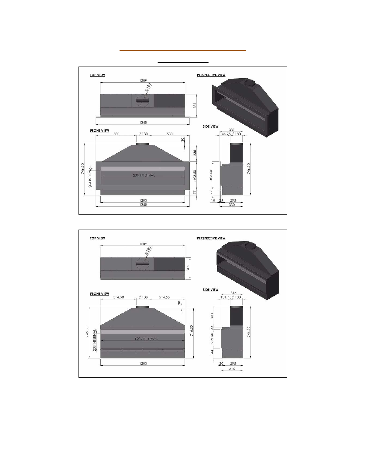
The minimum flue requirements for the FR1200 are a Class 1 Chimney or
177.8mm flue liner with a minimum length of 3m. The enclosure and flue must
be sealed in line with building regulations.
This fire is approved for use with Natural Gas Only.
Once installed all additional gas inlet holes in the enclosure must be sealed
with metal tape to avoid flame reversal which will damage the remote.

Page 11 of 62
It is important that the gas supply is disconnected before any old
existing surround and hearth is removed.
The gas connections must be in accordance with National Regulations. An
isolation valve, or valves, has to be fitted adjacent to the appliance which,
when closed, allow(s) the complete burner and control assembly to be
disconnected for maintenance or repair in accordance with National
Regulations. This is supplied with the fire.
The pilot light and flame sensing device fitted to this fire is also an atmosphere
sensing devise. If for any reason any part of the pilot assembly is to be
replaced ALL the assembly including the pilot burner, thermocouple, electrode
and injector must be exchanged complete for an original manufacturer’s pilot
assembly only. This atmosphere sensing devise is not adjustable and must not
be put out of action. The pilot light shuts off both the main burner and pilot if
evacuation of the combustion products is interrupted. If the fire shuts itself off,
do not use the fire, and have the flue and fire checked by a suitably qualified
person.
The FR1200 requires an air vent within the room which will provide a
minimum of 100cm2 free air in accordance with National Regulations. In some
countries additional ventilation may be required
It is recommended that a guard be used for the protection of young children,
the elderly or infirm.
A qualified Gas Safe Registered engineer should service the fire at least every
12 months. This will ensure the fireplace operates safely.
After installation, the chimney should be inspected and swept regularly to keep
the flue clear and free from debris and excessive build up of soot. The fire
needs to be covered up when work is undertaken, to ensure the unit does not
get damaged or gas outlets blocked.
Do not throw rubbish on the unit, or otherwise disturb the fuel bed, as this will
render the appliance highly dangerous.
Due to the newness of the materials, the fire may give off a slight smell for a
period of time after commissioning. This is quite normal and any odours should
disperse within a few hours of operation. Do not operate the appliance if
decorating or using scented candles. The particles will be drawn into the
fireplace and burnt causing staining and further smells.

Page 12 of 62
BEFORE STARTING TO INSTALL CHECK:
1. Gas Pipe Work: The fire is 10Kw and a strong gas supply is required. Did
you check the suitability of the pipework in line with the flow rates as shown
on page 5?
2. Air Ventilation: Make sure an air vent is installed in the room to provide
fresh air from outside. The air vent must supply a minimum of 100cm2 air in
to the room. If unsure about the amount of free air provided contact the air
vent supplier before installing the fire.
3. Chimney: Does the chimney or flue system meet the minimum
requirements as set out on page 5? Has the chimney been swept and
checked for leaks?
4. Burner Ventilation: If fitting the fire without the trim special air routing will
be required for the burner. See following Section for details.
Burner Ventilation
Read this section carefully before proceeding.
The burner requires ventilation air from the room to ensure the remote system
stays cool and operates correctly. The fire enclosure has been designed to allow
this air to be provided easily as long as the correct planning is done. If the air
requirement is ignored the fire will overheat and the remote will be damaged.
This is not covered by the warranty.
Air provided by the trim.

Page 13 of 62
When fitting the fire with the trim the air can be provided by the slot on the
enclosure. The plaster board must not cover the slot, the plaster board goes up
to the guide fitted on the fire. The fascia is mounted so that it allows air to pass
between it and the wall into the burner slot.
See Image Below.
The image shows the plaster board up to the guide bracket and air entering the
fireplace. This slot is then covered by adding the fascia trim.
Air provided when no trim is fitted.
This style of installation is more complicated
and needs careful planning. In order to allow
the plasterboard to be taken up to the edge
where the shelf is the guide must first be
removed. Inside the burner tray there is
another air slot in the base. This must be left
uncovered and used to provide the burner air.
See image below.
When there is no trim the burner ventilation air must come from the room. The
most popular way of achieving this is to route air from the skirting board level
into a chamber behind the plaster board which runs up to the slot in the base of
the burner tray. The air slot on the wall must be as wide as the slot in the fire
(750mm x 10mm) and must maintain this size or bigger into the burner tray.

Page 14 of 62
The channel must be sealed to ensure that no air from this channel can be
drawn up the chimney.
WARNING: Failure to provide the proper ventilation for the burner will
result in the remote system over heating and possibly damaged beyond
repair.

Page 15 of 62
Building and Installation Work
Gas Supply
Consult the Data Plate within the appliance to ensure the correct gas type and
pressure is available within the property. Before commencing to create the fire
opening for the inglenook unit note that a gas supply is required. The gas
supply pipe should run into the installed enclosure from either the rear, left or
right hand sides, the gas supply is best run through the right side of the
enclosure. CHECK GAS SUPPLY RATE BEFORE INSTALLING (SEE PAGE 5)
The fire has an 8mm inlet via an isolation valve. The fire also includes a
pressure test point elbow to test inlet pressure. The gas pipe work should be
routed into the enclosure via the available access holes. If the gas pipe work is
over 1.5mtrs in length it is recommended that the pipe work is increased in
diameter from this point to 15mm, 22mm and possibly 28mm depending on the
length to the meter – see technical section for gas consumption. This will
ensure a stable gas supply.
Building Work
It is important that the gas supply is disconnected before any old existing
surround and hearth is removed. Measuring from the floor surface, the intended
location of the base of the enclosure unit is marked onto the wall. Allowances
must be made for the steel gather, if required.
The enclosure should be located centrally to the existing flue/chimney at your
desired height. If the fire is not placed central to the chimney, the flame picture
may pull incorrectly. The area indicated on the wall must be removed to house
the Fire enclosure and burner unit. In some installations it may be necessary to
install a small lintel above the opening, if so an allowance must be made to
accommodate this lintel. (The Fire does not have its own lintel). After removing
the excess brickwork to the required height, the base of the fire opening (which
the Fire burner and enclosure will sit upon) has to be built.
To create a seal around the appliance and allow correct operation of the flue,
the original fire opening must be closed using bricks or blocks, infill the void
around the enclosure using block work or rubble. (It is advisable to install a
solid base inside the fire opening to sit the steel framework supporting the
burner unit on to.)
Installation Style:
The fire is supplied with the gather fitted, this must not be removed. The fire
can be used within an existing chimney/fireplace opening or within a new build

Page 16 of 62
with a false chimney breast. Choose the correct installation method as shown
below.
1. Within a Chimney/Fireplace Opening – See Below
2. In a New Build with False Chimney Breast – Go to Page 23
Installing within a Brick Chimney
Preparing the Fireplace Opening
The above image shows the minimum fireplace opening width and
height.
The image shows the fireplace opening required to install the fireplace unit. The
gather is fitted to the fire and cannot be removed hence there is a larger
opening height.

Page 17 of 62
Above shows the minimum depth of the wall and the maximum lintel size when
fitting the fire to allow the spigot on the gather to line up with the chimney.
Add 20mm to this for the front face of the finished wall (plaster board).
The enclosure can be deeper however any voids should be filled otherwise there
is a risk of “banging” when the enclosure expands and contracts with heat.
Inserting the Fireplace into the Opening.
Once the fireplace opening has been created the appliance can be lifted into the
opening. Feed the gas pipe through the chosen hole into the lower burner area
ready for connection later. Before the gas pipe can be fed into the enclosure the
vanity cover must be removed.
The vanity cover is in two parts – front and back. Only the front section needs
to be removed. This is done by removing the two screws on the sides of the
enclosure. Once the vanity cover has been lifted off ensure that this is stored in
a safe place with the screws.

Page 18 of 62
Fireplace Clearance
The fire must sit forward 20mm from the brickwork. This is for the plasterboard
that will be added later to finish the installation and create a letterbox style.
Position the enclosure in the opening so there is a minimum clearance of 10mm
on each side and 10mm at the top. This allows minor adjustment. This void
should be sealed with a suitable fire retardant material to seal the enclosure to
the opening.
Once installed in the opening the fire must be fixed down to the fireplace
opening using screws and plugs. This can be done by removing the vanity cover
and drilling through the base. Take care not to damage the connections or gas
pipes while drilling.

Page 19 of 62
The above shows the fire correctly positioned - spigot in line with the chimney.
The enclosure must sit 20mm forward of the brick wall to allow for plasterboard
to be added. See image above.
Note: The FR1200 is supplied with the gather fitted and sealed to the
enclosure. This gather must not be removed or modified in any way. The gather
is an integral part of the structure of the fireplace design.

Page 20 of 62
With a Flue Liner within a Brick Chimney
The flue liner must comply with the minimum size as specified in the technical
section on page 5. The liner must be sealed to the spigot.
Once the fire is fixed in place the void above the fire must be filled in as shown
below ready to be finished with plasterboard to create the final look required.
Table of contents
Popular Indoor Fireplace manuals by other brands

Hearth and Home Technologies
Hearth and Home Technologies BE-32 owner's manual

Dimplex
Dimplex BF392SD installation guide

Valor
Valor Firelite OXYSAFE 2 owner's guide

Quadra-Fire
Quadra-Fire Quadra-Fire 2700-I instruction manual

Majestic fireplaces
Majestic fireplaces DV580 Installation and operating manual

Quadra-Fire
Quadra-Fire QFP 30 Operation & maintenance manual