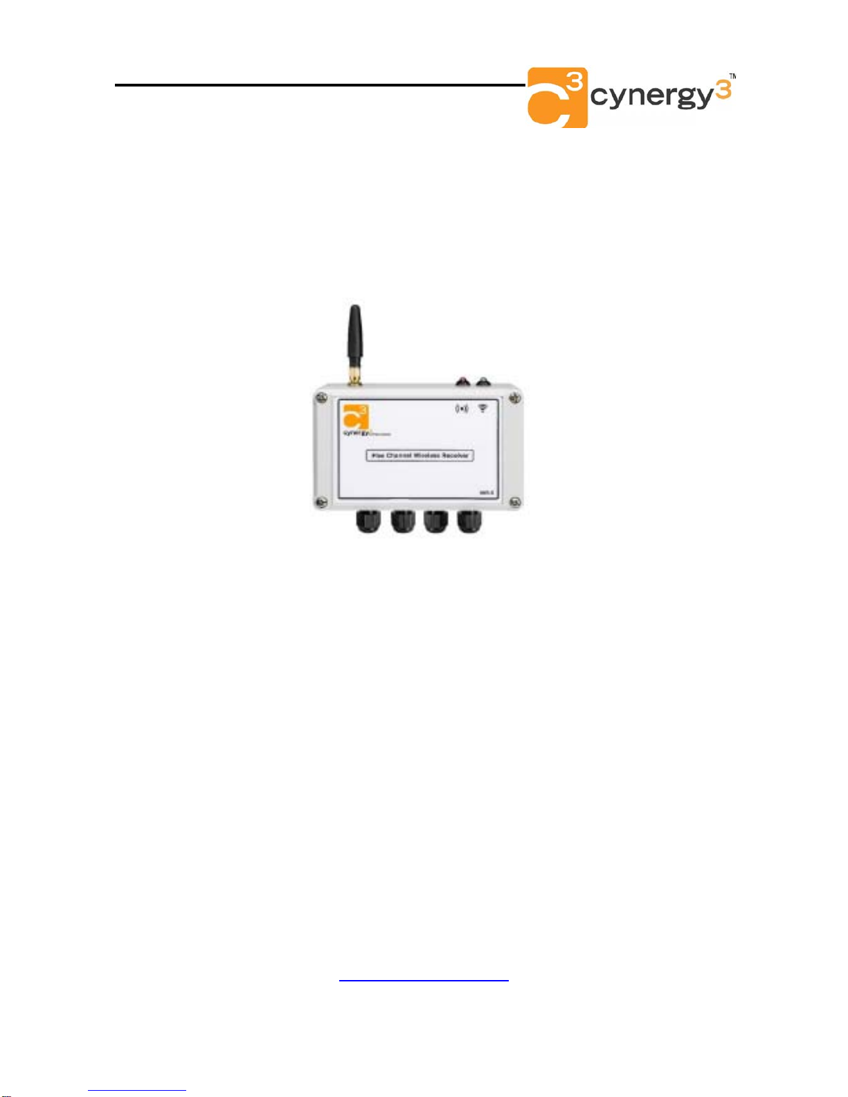
IWR-5 Wireless Pressure & Temperature Receiver - Operating Manual
Page 6 IWR-5 Iss2.1
If full scale calibration has been achieved LED1 will go amber for 0.5 seconds as calibration
values are learnt and saved to memory.
To cycle which channel is being calibrated push the UP or DOWN buttons until the LED
linked to the channel to be calibrated is lit. Repeat the above using the appropriate LED for
the channel selected.
The analogue output can be scaled to any part of the full scale range of the transmitter
connected.
For example an IWTT with a P100 input sends a temperature back between -200°C & 800°C. By
default the 4-20mA output will be at 4mA at -200°C and 20mA ay +800°C. The IWR-Set V2.1
software can be used to scale the 4-20mA so that 4mA is output at a temperature of 0°C and
20mA is output at a temperature of +500°C.
The set up procedure is intuitive once the IWR-SET software is opened on a PC and connected
to the IWR receiver using a standard micro USB cable.
If switches 5 & 6 are configured to switch the Alarm Relay if wireless transmissions are missed
the analogue output can also be set to go to a failsafe burnout output if no transmissions are
received.
If a 4-20mA output is selected the output will go to 2.2mA if Low Burnout is selected or 22.8mA if
High Burnout is selected.
If No Action (the default setting) is selected the analogue output will stay at the last valid value
received from the connected transmitter.
4. TROUBLE-SHOOTING GUIDE
Problem encountered Possible Causes
LED 7 doesn’t flash The IWR receiver is not connected to a transmitter or the
transmitters are out of range.
Any mA or Voltage Output channel
reads zero The IWR receiver output is not wired correctly, check
wiring and try again. If wiring is OK check the 4-20mA or
1-5Vdc selector switch is in the right position.
Output from any IWR receiver
channel isn’t equivalent to the
pressure or temperature being
monitored by the appropriate
transmitter.
Check that the IWR receiver is linked to the transmitter in
question by pressing the pushbutton inside the transmitter
and checking that LED 7 on the receiver flashes when the
transmitter button is pressed.
As above Check that the transmitter is set to the correct channel
number using the internal DIP switch.
LED 6 Remains Permanently Lit One of the transmitters is sending a value that is outside
the alarm conditions or the receiver is out of range of one
of the transmitters or one of the transmitters is switched
OFF.
The internal channel LEDs can be used to ascertain the
channel initiating the alarm and the type of alarm.
LED 6 is flashing This indicates that the battery inside the transmitter is
running low. Change the battery inside the transmitter
taking care to reset the battery level using the procedure
outlined in the transmitter manual.
The internal LEDs can be used to ascertain the channel
initiating the low battery alarm.