CZone Control X Guide

Control X
User & Installation Manual
V1.0

EN / CZone® Control X User & Installation Manual
2
Copyright
This document is copyright 2018 under the Creative Commons agreement. Rights are granted to research and
reproduce elements of this document for non-commercial purposes on the condition that BEP Marine is credited as the
source. Electronic re-distribution of the document in any format is restricted, to maintain quality and version control.
Important
BEP Marine strives to ensure all information is correct at the time of printing. However, the company reserves the right
to change without notice any features and specifications of either its products or associated documentation.
Translations: In the event that there is a difference between a translation of this manual and the English version, the
English version should be considered the official version.
It is the owner’s sole responsibility to install and operate the device in a manner that will not cause accidents, personal
injury or property damage.
Use of This Manual
Copyright © 2018 BEP Marine LTD. All rights reserved.Reproduction, transfer, distribution or storage of part or all of
the contents in this document in any form without the prior written permission of BEP Marine is prohibited.This manual
serves as a guideline for the safe and effective operation, maintenance and possible correction of minor malfunctions
of the Contact 6 PLUS.

3
EN / CZone® Control X User & Installation Manual
TABLE OF CONTENTS
1GENERAL INFORMATION 5
Use Of This Manual 5
Guarantee Specifications 5
Quality 5
Validity Of This Manual 5
Liability 5
Changes To The Control X 5
2SAFETY AND INSTALLATION PRECAUTIONS 6
Warnings And Symbols 6
Use For Intended Purpose 6
Organizational Measures 6
Maintenance And Repair 6
General Safety and Installation Precautions 6
3OVERVIEW 7
Description 7
Features 7
Control X Overview 8
LED Indicators 9
Capacitive Touch Panel 10
System Example 11
4INSTALLATION 12
Things You Need 12
Environment 12
Mounting 13
Planning 13
Connections 16
Set Dipswitch 19
Initial Power Up 19
Circuit Labeling 20
5H-BRIDGE MOTOR CONTROL 20
6BILGE PUMP MONITORING 21
7CZONE SWITCH INPUT RESISTOR MODULE (CZONE MUX) 22
8CONTROL X ADVANCED FEATURES 23
Wiper Synchronisation 23
RGBW LED Lighting control 24
9ORDERING INFORMATION 25
10 TECHNICAL SPECIFICATIONS 26
Dimensions 27
11 COMPLIANCE 28

EN / CZone® Control X User & Installation Manual
4
TABLE OF FIGURES
Figure 1. Product Overview......................................................................................................................8
Figure 2. LED Indicators ..........................................................................................................................9
Figure 3. CZone Control X Capacitive Touch Pannel............................................................................10
Figure 4. CZone Control X PLUS System Example...............................................................................11
Figure 5. Deutsch HDT-48-00 Crimp Tool .............................................................................................12
Figure 6. Mounting Screw Locations......................................................................................................13
Figure 7. Control X PLUS Channel Specifications.................................................................................14
Figure 8. Control X Channel Speifications.............................................................................................15
Figure 9. Control X Connections............................................................................................................16
Figure 10. Control X Main Supply Wiring...............................................................................................18
Figure 11. Setting Dipswitch ..................................................................................................................19
Figure 12. CZone Control X Labeling ....................................................................................................20
Figure 13. H-Bridge Direction Polarity Diagram.....................................................................................20
Figure 14. Bilge Pump Monitoring..........................................................................................................21
Figure 15. CZONE Multiplex Switch Input Wiring ..................................................................................22
Figure 17. RGB Control Example...........................................................................................................24
Figure 18. CZone Control X Dimensions ...............................................................................................27

5
EN / CZone® Control X User & Installation Manual
1 GENERAL INFORMATION
USE OF THIS MANUAL
Copyright © 2021 BEP Marine. All rights reserved.Reproduction, transfer, distribution or storage of part or all of the
contents in this document in any form without the prior written permission of BEP Marine is prohibited.This manual
serves as a guideline for the safe and effective operation, maintenance and possible correction of minor malfunctions
of the Control X and Control X PLUS. Both models will be referred to as Control X in this manual unless specified.
This manual is valid for the following models:
Description
Part number
CZONE CONTROL X PLUS C/W CONNECTORS
80-911-0230-00
CZONE CONTROL X PLUS INTERFACE ONLY
80-911-0230-01
CZONE CONTROL X C/W CONNECTORS
80-911-0231-00
CZONE CONTROL X INTERFACE ONLY
80-911-0231-01
It is obligatory that every person who works on or with the Control X is completely familiar with the contents of this
manual, and that he/she carefully follows the instructions contained herein.
Installation of, and work on the Control X, may be carried out only by qualified, authorized and trained personnel,
consistent with the locally applicable standards and taking into consideration the safety guidelines and measures
(chapter 2 of this manual). Please keep this manual in a secure place!
GUARANTEE SPECIFICATIONS
BEP Marine guarantees that this unit has been built according to the legally applicable standards and specifications.
Should work take place which is not in accordance with the guidelines, instructions and specifications contained in this
Installation manual, then damage may occur and/or the unit may not fulfil its specifications. All of these matters may
mean that the guarantee becomes invalid.
QUALITY
During their production and prior to their delivery, all of our units are extensively tested and inspected. The standard
guarantee period is two years.
VALIDITY OF THIS MANUAL
All of the specifications, provisions and instructions contained in this manual apply solely to standard versions of the
Control X,delivered by BEP Marine.
LIABILITY
BEP can accept no liability for:
•Consequential damage due to use of the Control X. Possible errors in the manuals and the results thereof.
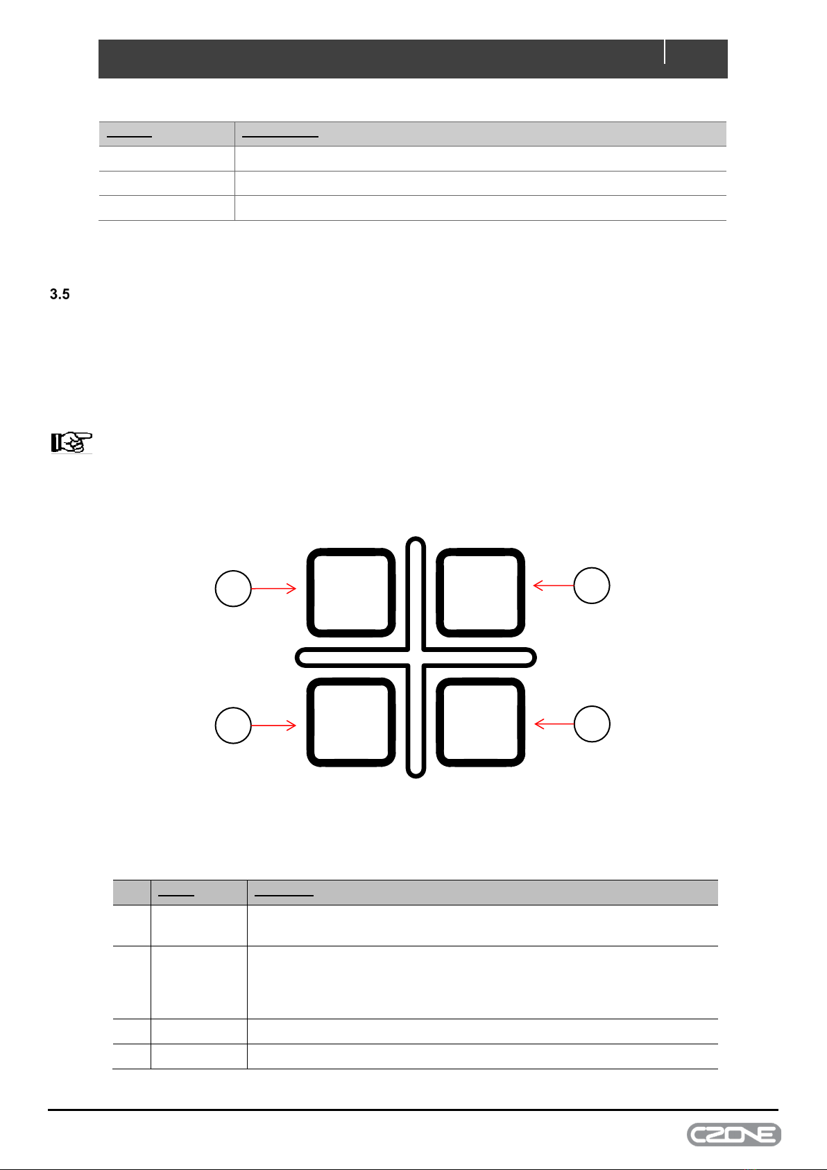
CAREFUL! Never remove the identification label
Important technical information required for service and maintenance can be derived from the type number plate.
CHANGES TO THE CONTROL X
Changes to the Control X may be carried out only after obtaining the written permission of BEP.

EN / CZone® Control X User & Installation Manual
6
2 SAFETY AND INSTALLATION PRECAUTIONS
WARNINGS AND SYMBOLS
Safety instructions and warnings are marked in this manual by the following pictograms:
CAUTION
Special data, restrictions and rules with regard to preventing damage.
WARNING
A WARNING refers to possible injury to the user or significant material damage to the Control X if the
user does not (carefully) follow the procedures.
NOTE
A procedure, circumstance, etc, which deserves extra attention.
USE FOR INTENDED PURPOSE
1. The Control X is constructed as per the applicable safety-technical guidelines.
2. Use the Control X only:
•In technically correct conditions
•In a closed space, protected against rain, moisture, dust and condensation
•Observing the instructions in the installation manual
3. Use of the Control X other than mentioned in point 2 is not considered to be consistent with the intended
purpose. BEP Marine is not liable for any damage resulting from the above.
ORGANIZATIONAL MEASURES
The user must always:
•Have access to the user's manual and be familiar with the contents of this manual
MAINTENANCE AND REPAIR
•Switch off supply to the system
•Be sure that third parties cannot reverse the measures taken
•If maintenance and repairs are required, only use original spare parts
GENERAL SAFETY AND INSTALLATION PRECAUTIONS
•Connection and protection must be done in accordance with local standards
•Do not work on the Control X or system if it is still connected to a power source. Only allow changes in
your electrical system tobe carried out by qualified electricians
•Check the wiring at least once a year. Defects such as loose connections, burned cables, etc. must be
corrected immediately

7
EN / CZone® Control X User & Installation Manual
3 OVERVIEW
DESCRIPTION
The Control X is CZone’s most flexible digital switching module yet, offering configurable input and output channels
allowing for multiple configuration options. The Control X features configurable software fusing, meaning no need to
purchase and install physical fuses. Current is monitored on all circuits to provide the overcurrent protection and circuit
bypass is available via the capacitive touch buttons on the module. The 45% smaller footprint than the COI/Control 1
has been achieved with an all-new electrical design and moulding the connector receptacles directly into the housing,
and a new IPX7 enclosure allows for installation in all environments.
FEATURES
•Compact size ensures ease of installation on wide range of boats and RV’s where space is limited.
•IPX7 enclosure allows for installation in all environments.
•100% solid state switching provides improved reliability, silent operation & smaller footprint than traditional
relays.
•Current is monitored and displayed for each circuit and also provides overcurrent protection and low
current/systems on detection.
•Software fuse ratings entered in configuration file, no need to purchase and install physical fuses.
•Configurable PWM Frequency.
•Automatic bilge pump feedback monitoring.
•Dual speed wiper motor controller with synchronization for up to 8 motors with 3 configurable intermittent timer
settings and the Control X PLUS has a switch to ground brake option for compatible wiper motors.
•RGB / RGBW lighting control with configurable zones for dimming, effects and sequences.
•Support for multiplex switch inputs means multiple mechanical switches can be connected to a single input
channel.

EN / CZone® Control X User & Installation Manual
8
CONTROL X OVERVIEW
Component
1.
Circuit Status Indication (Will vary between Control X and Control X PLUS specs)
2.
Circuit Label
3.
Main Supply Terminal Panel
4.
Dipswitch Cover
5.
Connector A - DTP06-4S
6.
Connector B - DT06-12SA
7.
Connector C - DT06-12SB
8.
NMEA2000 Micro C Connector
9.
Capacitive Touch Panel
10.
Module Power Indicator
11.
Network Power/Traffic Indicator
3
4
5
6 7
8
1
2
9
10
11
Figure 1. Product Overview

9
EN / CZone® Control X User & Installation Manual
LED INDICATORS
Figure 2. LED Indicators
1. Circuit Status LED’s
Colour
Description
Off
Channel Off
Green Solid On
Channel On
1 Red Flash
Module Not Configured
2 Red Flash
Configuration Conflict
3 Red Flash
DIP Switch Conflict
5 Red Flash
No Modules Detected
7 Red Flash
Over Current
9 Red Flash
Missing Commander
2. Power LED
Colour
Description
Off
Power Disconnected
Green
Power Available (>12V for 12V System, >20V for 24V System)
Red
Low Volts (<12V for 12V System, <20V for 24V System)
A Connector
B Connector
B Connector
Control X Plus
Control X
3
2
3
2
1
1

EN / CZone® Control X User & Installation Manual
10
3. Network Status LED
Colour
Description
Off
Network Power Disconnected
Green
Network Power Connected
Red Flash
Network traffic
CAPACITIVE TOUCH PANEL
The Control X has a capacitive touch panel for manual override of high-side output channels. Manual override will take
priority over any commanded circuit state, from CZone or any other device on the NMEA2000 network. Manual override
is available for the 16 high-side output channels, but not the 5A low-side output channels. Manually overridden states
(ON or OFF) will persist until either manually reset or the Control X has been power cycled.
NOTE - A long (200ms) press is required for operation of the touch pad buttons.
NOTE - A Control X with any circuit forced ON via manual override will not be able to be put to sleep until the
circuit has been reset. This is designed as a failsafe / get home state in case something on the network is forcing
the system to sleep.
Figure 3. CZone Control X Capacitive Touch Pannel
Label
Function
1. Next
Cycles through available output channels from left to right. The status
output LED will rapidly flash indicating the selected channel.
2. On
Forces selected channel to ON. If channel selected is the high side output
of an H-Bridge, the low side channel will also be turned ON. H-Bridge
channels are only momentarily turned on for safety incase motor is driving
a hatch lift or similar.
3.
Off
Forces selected channel to OFF.
4.
Reset
Restores selected channel back to standard operation.
2
1
3
4
RESET
OFF
NEXT
ON

11
EN / CZone® Control X User & Installation Manual
SYSTEM EXAMPLE
Figure 4. CZone Control X PLUS System Example
NMEA 2000 Network
CZONE KEYPAD
CZONE TOUCH 5
NAVIGATION
LIGHTS
CABIN
LIGHTS
COCKPIT
LIGHT
SALOON
LIGHTS
BILGE
PUMP
SALTWATER
PUMP
FRESHWATER
PUMP
BAIT TANK
PUMP
RGB LIGHTS COCKPIT FRESHWATER
TANK SENDER
RGBW
ZONE 1 RED
RGBW
ZONE 1 GREEN
RGBW
ZONE 1 WHITE
RGBW
ZONE 1 BLUE
SHUNT INPUT
BATTERY
SHUNT INPUT
LOAD
SALOON LIGHT
SWITCH TO NEG
CABIN LIGHT
SWITCH TO NEG
24HR BILGE PUMP
FLOAT SWITCH
RGB LIGHTS SALOON
PORT WIPER
STBD WIPER
H-BRIDGE
FUEL TANK
SENDER
RESET
OFF
NEXT
ON
PUMP
SALOON
LIGHTS
PORT WIPER LOW
STBD WIPER LOW
PORT WIPER HIGH
STBD WIPER HIGH
PORT WIPER PARK
STBD WIPER PARK
M
ENGINE
HATCH LIFT
HOUSE BATT
12V
NAV
LIGHTS
CABIN
LIGHTS
BAIT
TANK
COCKPIT
LIGHT
BILGE

EN / CZone® Control X User & Installation Manual
12
4 INSTALLATION
THINGS YOU NEED
•Control X Module
•Deutsch Connector Kit (80-911-0233-00 – Control X, 80-911-0232-00 – Control X PLUS)
•4 x 10G (5mm) panhead self-tapping screws or bolts for mounting Control X to surface (not supplied)
•HDT-48-00 Deutsch crimp tool for crimping 0.5mm-4mm (20-12AWG) wire
•Duratool D03008 crimp tool or similar for crimping 6mm (10AWG) wire (optional)
•NMEA2000 drop cable and T-connector
•Screwdriver and drill bits
•Electrical Tools
•Silicone grease (lubricating connector seals)
Figure 5. Deutsch HDT-48-00 Crimp Tool
ENVIRONMENT
Obey the following stipulations during installation:
•Ensure the Control X is located in an easily accessible location for quick access to module
•Ensure indicator LEDs are visible for troubleshooting
•Ensure circuit labels are fitted and all channels labelled correctly
•The Control X must be mounted at least 50mm away from high current carrying conductors such as anchor
winches, bow thruster cables, speakers, transformers and other high inductive loads.
•Ensure the bulkhead that the unit will be attached to is sufficiently strong to take the weight of the unit and
attached cables.
•Ensure there is at least 10mm clearance around the sides and top of the Control X.
•All connectors must be installed to achieve IPX7 waterproof rating with unused channels blocked with Deutsch
blocking pins (part # 114017-ZZ).

13
EN / CZone® Control X User & Installation Manual
MOUNTING
Figure 6. Mounting Screw Locations
1. Place Control X on a solid flat surface. Mark the lower screw locations.
2. Remove Control X and partially install lower screws using 10G (5mm) self-tapping screws or bolts.
3. Slot the Control X on to the bottom screws and install upper retaining screws.
4. Torque down each mounting screw, 6Nm max.
5. Ensure enough space is left below the Control X to easily install cable connectors and access for
maintenance.
PLANNING
Make a list of all inputs and outputs to be wired to the Control X and take note of the output channel ratings and functions
as shown in Figure 7 and Figure 8. Assign each input and output to a channel on the Control X ensuring loads are wired
to the appropriate channel for the functionality required.
•All high-side output channels have the option to alarm on detection of external voltage, useful for circuits such
as Bilge Pumps with an external or “automatic” supply from a float switch. This feature reduces wiring by
allowing control and feedback from a single wire.
•For loads with a continuous current exceeding max channel current, it is possible to parallel high-side or low-
side output channels.
•Maximum module current must be taken into consideration:
oControl X PLUS – 120A
oControl X – 100A
•Maximum current for each connector must be taken into consideration:
oConnector A – 50A (Control X PLUS Only)
oConnector B – 80A
oConnector C – 30A (Control X PLUS), 20A (Control X)

EN / CZone® Control X User & Installation Manual
14
Control X Plus
Connector
Number
Max
Current
Output
High-Side
Output
Low-Side
Signal
Input
Bilge
Sensing
Light
Dimming
H Bridge
Parallel
Circuits
RGB
Zone
Channel Notes
4x 15A High Side Outputs or 2x H-Bridge – 50A Connector Max
A1
15A
A2
15A
H-Bridge channels
A3
15A
can’t be paralleled
A4
15A
12x 10A High Side Outputs or 12x Full SI Inputs – 80A Connector Max
B1
10A
B2
10A
B3
10A
B4
10A
B5
10A
B6
10A
B7
10A
B8
10A
B9
10A
B10
10A
B11
10A
B12
10A
8x 5A Low Side Outputs or 10x Full SI Inputs, Shunt Input – 30A Connector Max
C1
Shunt Input (+)
C2
Full SI Only (Ignition Wake)
C3
5A
RGBW Z2 Red
C4
5A
RGBW Z2 Green
C5
5A
RGBW Z1 Red
C6
5A
RGBW Z1 Green
C7
5A
RGBW Z1 Blue
C8
5A
RGBW Z1 White
C9
5A
RGBW Z2 Blue
C10
5A
RGBW Z2 White
C11
Full SI Only (Ignition Wake)
C12
Shunt Input (-)
1 2
4 3
1 2
12 11
3 4
10 9
56
8 7
1 2
12 11
3 4
10 9
5 6
8 7
AB C
10A high side outputs
Or
Signal Inputs
Shunt Input
5A low side outputs
or
Signal Inputs
Signal Inputs
Only
15A high side outputs
Or
2 x 15A H-Bridge
Figure 7. Control X PLUS Channel Specifications

15
EN / CZone® Control X User & Installation Manual
Figure 8. Control X Channel Speifications
Control X
Channel
Pinout
Max
Current
Output
High-Side
Output
Low-Side
Signal
Input
Bilge
Sensing
Light
Dimming
H Bridge
Parallel
Circuits
RGB
Zone
Channel Notes
12x 10A High Side Outputs or 12x Full SI Inputs – 80A Connector Max
B1
10A
B2
10A
B3
10A
B4
10A
B5
10A
B6
10A
B7
10A
B8
10A
B9
10A
B10
10A
B11
10A
B12
10A
4x 5A Low Side Outputs or 10x Full SI Inputs, Shunt Input – 20A Connector Max
C1
Shunt Input (+)
C2
Full SI Only (Ignition Wake)
C3
Full SI Only
C4
Full SI Only
C5
5A
RGBW Z1 Red
C6
5A
RGBW Z1 Green
C7
5A
RGBW Z1 Blue
C8
5A
RGBW Z1 White
C9
Full SI Only
C10
Full SI Only
C11
Full SI Only (Ignition Wake)
C12
Shunt Input (-)
1 2
12 11
3 4
10 9
5 6
8 7
1 2
12 11
3 4
10 9
5 6
8 7
BC
10A high side outputs
only
Shunt Input
5A low side outputs
or
Signal Inputs
Signal Inputs
Only

EN / CZone® Control X User & Installation Manual
16
CONNECTIONS
Figure 9. Control X Connections
1. Connector A (Control X PLUS Only)
1. Referring to the load list, strip and crimp the High Current or H-Bridge cables
with the appropriate Deutsch contact and crimp tool.
2. Insert the contacts into the DTP06-4S plug following the plugs position
numbers and secure using the locking wedge.
3. Any unused pins in the connector should be plugged with sealing plugs to
maintain the IPX7 rating. (Deutsch part # 114017-ZZ).
4. Before inserting the connector it’s highly recommended to apply a small
amount of silicone grease along the sealing surfaces/gasket. This will make
assembly/disassembly easier.
5. Insert the connector into the Control X PLUS until it clicks into place.
6. Secure and neaten up the cables against the bulkhead to reduce the strain on
the connectors.
NOTE – Connector A on the Control X will be sealed from the factory. No
blanking plug will be required.
A
B
C
Main DC Positive
& Negative
NMEA2000 Connector
RESETNEXT
DTP06-4S
DT06-12SA
DT06-12SB

17
EN / CZone® Control X User & Installation Manual
2. Connector B
1. Referring to the load and signal input list, strip and crimp the cables with the
appropriate Deutsch contact and crimp tool.
2. Insert the contacts into the DT06-12SA plug following the plugs position
numbers and secure using the locking wedge.
3. Any unused pins in the connector should be plugged with sealing plugs to
maintain the IPX7 rating. (Deutsch part # 114017-ZZ).
4. Before inserting the connector it’s highly recommended to apply a small
amount of silicone grease along the sealing surfaces/gasket. This will make
assembly/disassembly easier.
5. Insert the connector into the Control X until it clicks into place.
6. Secure and neaten up the cables against the bulkhead to reduce the strain
on the connectors.
3. Connector C
1. Connector C has a number of different inputs and outputs available.
Check the table above to ensure your circuit channel is adequate for the
function required. Referring to the circuit list, strip and crimp the input/output
cables with the appropriate Deutsch contact and crimp tool.
NOTE – Pins 1 and 12 are dedicated shunt input pins only. The shunt must
be connected to the same battery as the module input studs and must be
connected to the battery negative.
2. Insert the contacts into the DT06-12SB plug following the plugs position
numbers and secure using the locking wedge.
3. Any unused pins in the connector should be plugged with sealing plugs to
maintain the IPX7 rating. (Deutsch part # 114017-ZZ).
4. Before inserting the connector it’s highly recommended to apply a small
amount of silicone grease along the sealing surfaces/gasket. This will make
assembly/disassembly easier.
5. Insert the connector into the Control X until it clicks into place.
6. Secure and neaten up the cables against the bulkhead to reduce the strain
on the connectors.
4. Connect NMEA2000 network
1. Connect a NMEA2000 drop cable from the Control X to a NMEA2000 backbone.
2. Ensure the NMEA2000 network is properly terminated and connected to a 12V power source (Do not
power up network yet).

EN / CZone® Control X User & Installation Manual
18
5. Connect DC Negative
1. Connect an appropriately sized cable from the battery negative terminal or main negative bus to the Control
X’s M8 negative stud.
2. The Negative cable must be of sufficient size to carry the maximum current of all low side outputs and H-
Bridge circuits connected to the Control X, volt drop should be kept to a minimum.
3. Maximum recommended cable size is 50mm² (1/0 AWG). Cables larger than 50mm² (1/0 AWG) should be
connected to a joiner stud first with a link to the Control X.
4. Ensure supplied spring washer is installed and M8 nut is torqued to 10Nm max.
6. Connect DC Positive
1. Connect an appropriately sized and fused cable from the battery positive terminal to the Control X’s M8
positive stud.
2. The positive cable must be of sufficient size to carry the maximum current of all loads connected to the
Control X and have a fuse/circuit breaker rated to protect the cable, volt drop should be kept to a minimum.
3. Maximum recommended cable size is 50mm² (1/0 AWG). Cables larger than 50mm² (1/0 AWG) should be
connected to a joiner stud first with a link to the Control X.
4. Ensure supplied spring washer is installed and M8 nut is torqued to 10Nm max.
5. Install stud cover over studs.
Figure 10. Control X Main Supply Wiring

19
EN / CZone® Control X User & Installation Manual
SET DIPSWITCH
1. With a screwdriver, remove the dipswitch cover from the Control X.
2. Using a small screwdriver, carefully set the dipswitch to the required setting. The dipswitch number must be
unique for all modules on the CZone network and must match the dipswitch setting in the configuration to
function correctly.
3. Replace dipswitch cover once correct dipswitch setting has been configured, ensuring not to overtighten screws.
NOTE – Control X is only Ingress Protected and Ignition Protected when dipswitch cover is fitted correctly.
The example shows a dipswitch number of 10000000 where 0 = Off and 1 = On.
Figure 11. Setting Dipswitch
INITIAL POWER UP
1. Check all plugs are securely seated and power connections are tight.
2. Check dipswitch setting of Control X to match with new configuration.
3. Turn the switch/circuit breaker on supplying the Control X’s main positive stud.
4. Check that the Power indicator LED is green.
5. Power up the NMEA2000 network.
6. Check that the NMEA2000 Network LED lights up. It may also be flashing if other devices are present and
transmitting data.
7. Check the circuit’s status LEDs for each individual circuit. Refer to LED codes to diagnose any faults which
need to be rectified.
8. Check the software version of all modules on the network, including the Control X, with the CZone Configuration
Tool and update if necessary.
9. Write configuration file to the Control X and the rest of the CZone modules on the system (Refer to the CZone
Configuration Tool Instructions for details on how to configure the Control X).
10. Test all inputs and outputs for configured functionality.
1
2

EN / CZone® Control X User & Installation Manual
20
CIRCUIT LABELING
Figure 12. CZone Control X Labeling
Label the Circuits
•The Control X is supplied with labels to fit into the indentations under each circuit LED indicator.
•Custom label sets can be ordered for a more complete finish in OEM installations.
5 H-Bridge Motor Control
2 x 15A H-Bridge channels are included on the Control X PLUS allowing reversing motors to be connected directly to
the module. The channels are available on Plug A. A combination of 1x H-Bridge output and 2x single channel outputs,
or 2x H-Bridge outputs can be configured.
Motor polarity for each of the H-Bridge outputs for forward and reverse is shown below:
FORWARD
H-BRIDGE 1
Pin 1 = Positive
Pin 2 = Negative
H-BRIDGE 2
Pin 3 = Positive
Pin 4 = Negative
H-BRIDGE 1
Pin 1 = Negative
Pin 2 = Positive
H-BRIDGE 2
Pin 3 = Negative
Pin 4 = Positive
REVERSE
Figure 13. H-Bridge Direction Polarity Diagram
RESET
OFF
NEXT
ON
Table of contents
Other CZone Network Accessories manuals