CORNING Evolv PAC 864/576 User manual

003-1072-AEN, Issue 2
STANDARD RECOMMENDED PROCEDURE 003-1072-AEN | ISSUE 2 | MARCH 2021 | PAGE 1 OF 11
Evolv™ Corning PAC 864/576
Pad-Mounted Cabinet
related literature | Search www.corning.com/opcomm. Click on “Resources.”
003-763 Instruction, OptiTect®LS S plitter Module
006-111 Instruction, Optical Access Connector Cleaning Kit
000-228 Instruction, Hardware-Mounting Kits for OptiTect Cabinets
1. General
Figure 1 provides a pictorial description of the preconnectorized conguration of the cabinet and
its components.
Subscriber
distribution
eld
Feeder and
pass-through
panel Door
restraint
Door
latch
Splitter module
storage housings
Lifting eye
safety loop
Storage eld
for unused
connectors
Radius guides
Skirt (pad-mount cabinets only)
TPA-6656
Figure 1

STANDARD RECOMMENDED PROCEDURE 003-1072-AEN | ISSUE 2 | MARCH 2021 | PAGE 2 OF 11
The following carton contents are included but not illustrated:
(1) PAC 864/576 pad-mounted cabinet prestubbed with distribution and feeder cables in
length specied by the customer
(1) Bag with extra adapter and connector dust caps
(1) Hardware-mounting kit containing:
(1) Installation instruction (003-756)
(1) Installation instruction (000-228)
(6) Split-lock washers
(6) Flat washers
(6) Hex nuts
(6) Screws
(1) Pad-mounting template
(1) Isolation pad (rubber cushion)
2. Tools and Materials Required
2.1 Materials
The following materials are required to install the cabinet onto a pad (pad is purchased
separately):
• Paper-mounting template (provided)
• p/n 02-005333-001 mounting template for large footprint cabinets
• p/n 02-005333-002 mounting template for small footprint cabinets
• Rubber-mounting cushion (isolation pad)
• Hardware-mounting kit (provided)
For mounting on a pad by inserting threaded inserts or wedge anchor threaded studs, order
pad-mount kit (p/n FDH-LS-ANCHOR-864).
2.2 Tools
To install the cabinet, the following tools may be required:
• Hoist or lifting device capable of lifting at least 250 pounds (including packaging)
• Forklift or hand truck
• 216B tool or a 7/16-inch nutdriver (for entry into the interior of the cabinet)
• Crescent wrench
• Drill with 7/8- to 1-inch auger bit
• 9/16-inch nut driver or socket
• 3/4-inch nut driver or socket
• Phillips-head screwdriver
• Dry-process connector cleaning supplies

STANDARD RECOMMENDED PROCEDURE 003-1072-AEN | ISSUE 2 | MARCH 2021 | PAGE 3 OF 11
3. Storage and Transportation
The shipping container and its contents must be stored indoors in a vertical position in the
original packaging. A forklift or hand truck capable of lifting approximately 250 pounds is
required to unload or transport the product in its shipping container prior to unpacking. Observe
all local safety precautions when moving the container. Do not double stack shipping containers.
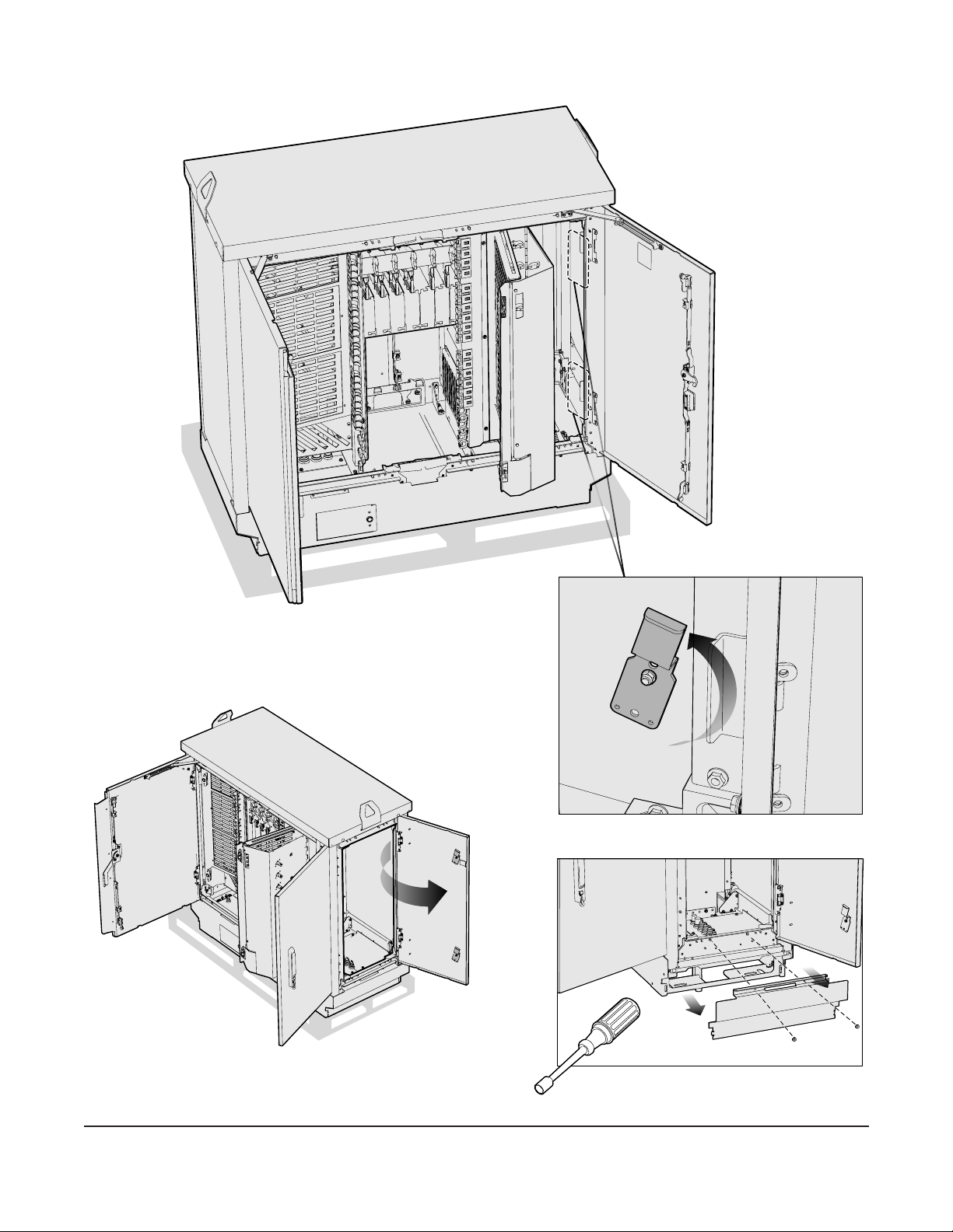
4. Unpacking the Cabinet and Components
Step 1: Place the container
near the site prepared
for installation of the
cabinet.
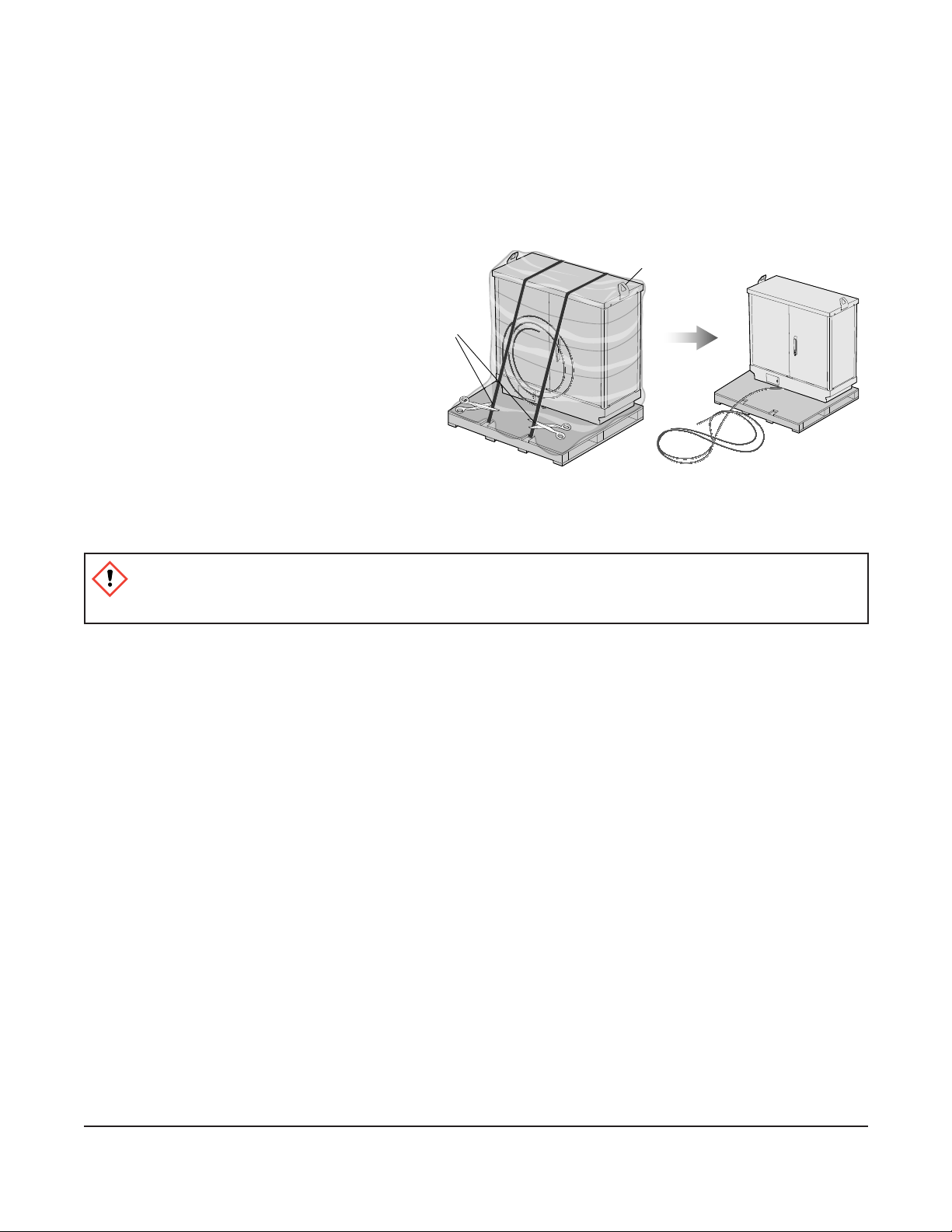
Step 2: Cut the bands holding
the cabinet to the pallet.
Step 3: Remove the
shrinkwrapping from
around the cabinet
(Figure 2).
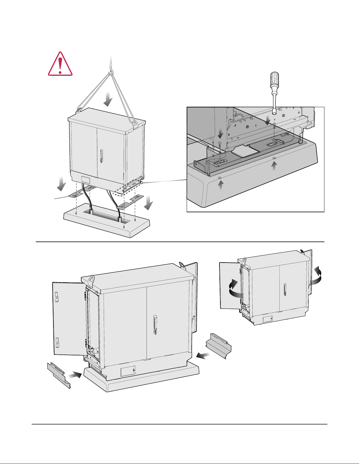
5. Installing the Cabinet on a Pad
DANGER: Only certied operators should operate the crane. Ensure that stabilizers are
extended and rmly positioned before lifting. Avoid overhead obstructions or power lines when
lifting.
IMPORTANT: Ensure that a lifting device, such as a hoist or crane, capable of lifting at least 250
pounds is available to lift the cabinet into position. The cabinet is heavy and requires two
people to maneuver it. Observe all safety precautions while using the cable hoist. Make
sure the door is locked in the closed position. Failure to do so may result in personal
injury or damage to the cabinet or cables.
5.1 On a pad
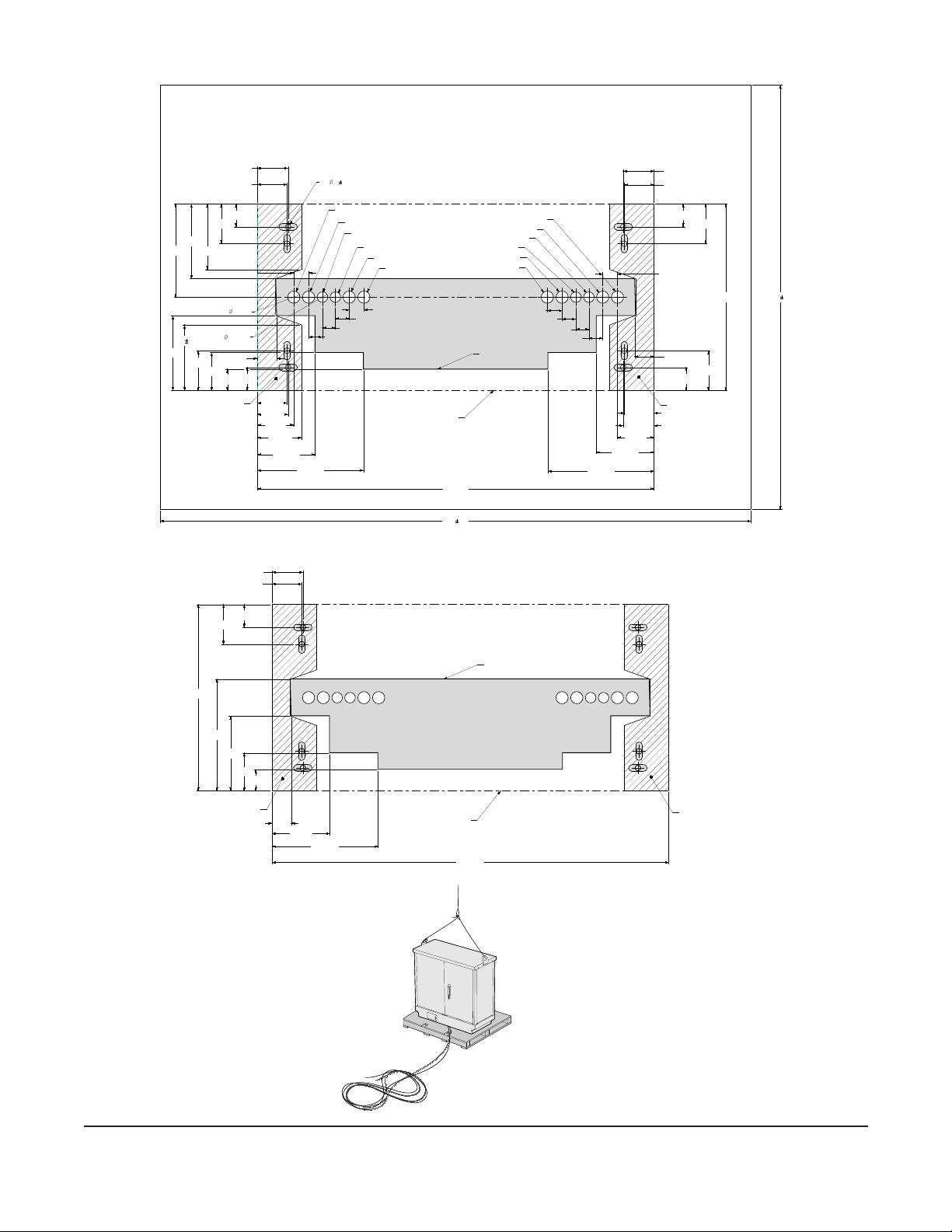
Step 1: If not using a precast pad with mounting hardware installed, use the provided
template to mark the location for the mounting bolts (Page 5). Drill holes for 0.5-inch
bolt anchors in the poured pad and insert the mounting bolts (0.5-inch diameter). Or
use an anchor assembly kit (FDH-LS-ANCHOR-432 or FDH-LS-ANCHOR-864).
Step 2: Clip the ties from the cables. Roll out the cables when removing them from the
packaging to avoid putting twists into the cable. Then loop the cables in a “Figure-8”
pattern next to the mounting location before placing the cabinet (Figure 2).
IMPORTANT: Fiber optic cable is sensitive to excessive pulling, bending and crushing forces. Do not
exceed 200 pounds of pulling force on the cable. Do not bend the cable more sharply
than the minimum recommended bend radius (typically 9 inches). Do not crush the cable
or allow it to kink. Doing so may alter the transmission characteristics of the cable.
Cut bands
here
Lifting eye
safety loop
TPA-6657
Figure 2
Note: Side panels may be packaged separately

216B Tool
X2
Click
1 2 3
TPA-6658
216B Tool
6. Pad-mounting Preparations
6.1 Unlocking the cabinet
STANDARD RECOMMENDED PROCEDURE 003-1072-AEN | ISSUE 2 | MARCH 2021 | PAGE 4 OF 11

1150 1,2
1600 1,2
8X 15 0,5
MOUNTING HOLES
1075 mm
505 mm
83,5 mm
80,5 mm
62 mm
107,5 mm
83,5 mm
80,5 mm
62 mm
107,5 mm
62 mm
107,5 mm
83,5 mm
80,5 mm
107,5 mm
62 mm
83,5 mm
80,5 mm
202,5 mm
52,5 mm
202,5 mm
52,5 mm
40 mm
37,5 mm
252,5 mm
40 mm
35 mm
37,5 mm
99 mm
99 mm
40 mm
40 mm
37,5 mm
35 mm
37,5 mm
8X 33 mm
4X 28,5 mm
102,5 mm
57,5 mm
156,5 mm
287,5 mm
156,5 mm
287,5 mm
120 mm
177,5 mm
177,5 0,5
CABINET MOUNTING
SURFACE CABINET MOUNTING
SURFACE
CABINET FOOTPRINT
Front
DISTRIBUTION #2
DISTRIBUTION #1
FEEDER/PASS-THRU #1
DISTRIBUTION #4
DISTRIBUTION #3
PASS-THRU #2
EXPANSION DISTRIBUTION #2
EXPANSION DISTRIBUTION #4
EXPANSION DISTRIBUTION #1
EXPANSION FEEDER/PASS-THRU #1 EXPANSION DISTRIBUTION #3
EXPANSION FEEDER/PASS-THRU #2
PAD CUTOUT
Mounting Template
PAC 864/576 Metric
42 5/16 IN
4 IN
8 IN
11 5/16 IN
6 1/8 IN
2 IN
19 7/8 IN
12 IN
4X 2 1/2 IN
4X 4 1/4 IN
4X 3 1/4 IN
4X 3 1/8 IN
2 1/4 IN
CABINET MOUNTING
SURFACE
CABINET MOUNTING
SURFACE CABINET FOOTPRINT
PAD CUTOUT
Front
Mounting Template
PAC 864/576 English
TPA-6659
TPA-7057
6.1 Pad-mounting Diagrams
STANDARD RECOMMENDED PROCEDURE 003-1072-AEN | ISSUE 2 | MARCH 2021 | PAGE 5 OF 11

X2
8 mm
Nut driver
TPA-6661
7. Remove Side Panels
STANDARD RECOMMENDED PROCEDURE 003-1072-AEN | ISSUE 2 | MARCH 2021 | PAGE 6 OF 11
Note: Side panels may be packaged separately

Isolation
pad (X2)
X4
8 mm
nut driver
TPA-6662
8. Pad-mounting Preparations
STANDARD RECOMMENDED PROCEDURE 003-1072-AEN | ISSUE 2 | MARCH 2021 | PAGE 7 OF 11

9. Ground the Cabinet
TPA-6664
Click
TPA-6663
STANDARD RECOMMENDED PROCEDURE 003-1072-AEN | ISSUE 2 | MARCH 2021 | PAGE 8 OF 11

216B Tool
TPA-6665
Cable ground to
toner panel ground
10. Cable Toning
Access to the terminals allows for selective cable toning.
Step 1: Open the door of the ISO ground assembly using a 216B tool. (Figure 3).
Step 2: Loosen the terminal nut on the applicable cable to disengage (or “un-ground”) the
cable.
Step 3: Attach toning instrument.
Step 4: Record information appropriately on the labels provided on the inside of the door.
Step 5: When toning is complete, remove toning instrument and secure previously loosened
terminal screw.
Step 6: Close the door and secure it with a 216B tool.
Figure 3
STANDARD RECOMMENDED PROCEDURE 003-1072-AEN | ISSUE 2 | MARCH 2021 | PAGE 9 OF 11

If your application requires high bandwidth, by-pass the splitter modules and install jumpers
(patch cords) directly into the distribution and feeder ports.
Step 1: Lower the laser safety shutter on the feeder ber port to be connected.
Step 2: Verify with a power meter that the power is o. If not, turn it o at the central oce
before proceeding.
Step 3: Clean the adapter using a dry process. Corning Optical Communications
recommends use of the Corning IBC™ Brand Cleaner (Corning p/n CLEAN-
PORT-2.5) to clean the connectors and adapters before mating. Follow the
instructions provided with the cleaning tool.
Step 4: Remove the connector dust cap from the jumper (patch cord).
Step 5: Clean the connector using a dry process. Mate the connector into the appropriate
feeder port.
Step 6: Open the module housing by ipping the latch down and pulling the housing towards
you.
Step 7: Route the jumper through the routing clips in the bracket behind the module housing
label plate.
11. By-passing the Splitter Modules
STANDARD RECOMMENDED PROCEDURE 003-1072-AEN | ISSUE 2 | MARCH 2021 | PAGE 10 OF 11
WARNING: Never look directly into the end of a ber that may be carrying laser light.
Laser light is invisible and can damage your eyes. Viewing it directly does not cause pain. The
iris of the eye will not close involuntarily as when viewing a bright light. Consequently, serious
damage to the retina of the eye is possible. Should accidental eye exposure to laser light be
suspected, arrange for an eye examination immediately.
Step 8: Close the module housing by sliding the housing back into the cabinet and closing
the latch.
Step 9: Remove the connector dust cap from the jumper (patch cord). Clean the connector
end-face using a dry process, such as with a cleaning cassette or per your company
cleaning procedures.
Step 10: Mate the connector into the appropriate distribution port.
Step 11: Route the slack ber around radius control guides.
Step 12: Record information appropriately on the label inside the cabinet door. Good
recordkeeping is imperative for an organized installation.
Step 13: Power may now be turned on to the newly connected feeder port.

STANDARD RECOMMENDED PROCEDURE 003-1072-AEN | ISSUE 2 | MARCH 2021 | PAGE 11 OF 11
Corning Optical Communications LLC • 4200 Corning Place • Charlotte, NC 28216 USA
800-743-2675 • FAX: 828-325-5060 • International: +1-828-901-5000 • www.corning.com/opcomm
Corning Optical Communications reserves the right to improve, enhance, and modify the features and specications of Corning Optical Communications products
without prior notication. A complete listing of the trademarks of Corning Optical Communications is available at www.corning.com/opcomm/trademarks. All other
trademarks are the properties of their respective owners. Corning Optical Communications is ISO 9001 certied. © 2011, 2014, 2015, 2019 Corning Optical
Communications. All rights reserved.
1. In the event of high attenuation, the connectors can be removed and cleaned.
2. Metal components may be cleaned occasionally with a damp, nonabrasive cloth. Repaint
any bare metal with touch-up paint, which can be ordered separately
(p/n FDH-PNTKIT-A=almond; FDH-PNT-KIT-B=maple brown; FDH-PNT-KIT-G=green).
3. In the event of ice buildup on the outside surfaces and latches, use a cordless heat gun on low
heat to melt the ice.
CAUTION: Do not use any open ames or hammers to remove the ice.
When all work operations inside the cabinet are complete, secure the cabinet door.
Step 1: Install the rear door, if it was removed.
Step 2: Disengage the door restraint by gently lifting it to release the door.
Step 3: Close the door and rotate the handle 90 degrees clockwise. Press handle into cabinet
to lock the door latch. For additional security, insert a padlock (purchased separately)
through the holes in the hasp around the latch.
216B Tool
1 2 3
TPA-6766
12. Securing the Cabinet
13. Maintenance
Table of contents
Popular Network Accessories manuals by other brands

NetComm
NetComm NP290W quick start guide

Paradyne
Paradyne 8820 installation guide

AMG Systems
AMG Systems AMG2783A-1-DR-CWDMnm-SF instruction manual

Siemens
Siemens HiPath 3000 V3.0 or later Gigaset M1... Service manual

Paradyne
Paradyne 3172 Operator's guide

Extreme Networks
Extreme Networks GBX Installation and user guide