D-Link xStack Storage DSN-5000-10 User manual

Page 1
E
X
P
A
N
S
I
O
N
A
R
R
A
Y
DSN-5000-10 Expansion Array – 5/2010 Copyright © 2010 D-Link, Inc. - All Rights Reserved
DSN-5000-10 ExpansionArray
Quick Start Guide
The DSN-5000-10 Expansion Array Quick Start Guide provides
the information needed to connect additional DSN-5000-10
hot-pluggable expansion arrays to your primary array: up to
three to your DSN-5110-10, and up to six to your DSN-5210-10
or 5410-10. Each expansion array provides an additional 12
drive slots, and is equipped with one or two I/O Modules. The
dual I/O Module expansion array is used with a dual-controller
primary array for high availability in the event of a failure on
one controller.
Important Safety Information:
Use only the expansion arrays and cables provided by D-Link. DO
NOT use any other cable to connect the expansion arrays.
Before you install the DSN-5000-10 expansion array, please read
all documentation provided on the Product CD.
If you are adding a third or subsequent expansion array, you must
obtain a SAS-to-SAS expansion cable for each I/O module in the
additional arrays. This cable is not included with the Expansion
Array, but it is available at no cost from D-Link.
1 Unpack the Package Contents
Before unpacking, inspect the container for damage. If damage
exists, file a claim with the carrier. Remove the items from the
container and compare them to the packing list:
One DSN-5000-10 expansion array (includes backplane, 12 drive
carriers with drive blanks, two power supplies, 48 drive carrier
screws holding drive blanks, and one canister filler plate)
One expansion I/O module in a canister, inserted into the rear of
the DSN-5000-10 chassis
One SAS expansion cable (primary-to-expansion array)
and two power cords.
One rack-mount kit in a box (includes rails and mounting
hardware)
One DSN-5000 Series CD
One set of packing materials and cartons
If contents are missing or damaged please contact your supplier.
Save all packing materials in case you have to return the unit.
2 What Else You Need
To complete the expansion array installation, you need SATA or
SAS drives to be installed in the expansion array(s), and a
connection to a DSN-5110-10/5210-10/5410-10 primary array.
Note: The DSN-5000 Series primary array can support SAS or SATA
hard disk drives from a variety of manufacturers (48 for the DSN-
5110-10 and 84 for the DSN-5210-10 & 5410-10). It is possible (but
not recommended) to mix SAS and SATA drives in the same array.
Also, if you anticipate using dual controllers for HA operation, SAS
drives are required.
3 Rack-Mount Instructions
The DSN-5000-10 expansion arrays can be mounted in a standard
19-inch rack using the rack-mount kit provided with the DSN-5000-
10 expansion array.
Note: The rack cabinet must provide sufficient airflow to the front
and back of the expansion arrays for correct cooling. Ventilation
must be sufficient to exhaust heat from the equipment at the rear
of the rack. Plan the rack installation with the heaviest item on
the bottom of rack.
A. Ensure power is not being applied to the DSN-5000-10
expansion array by removing the power cords before
attaching the mounting hardware provided to the left and
right sides of the rack supporting the DSN-5000-10 expansion
array.
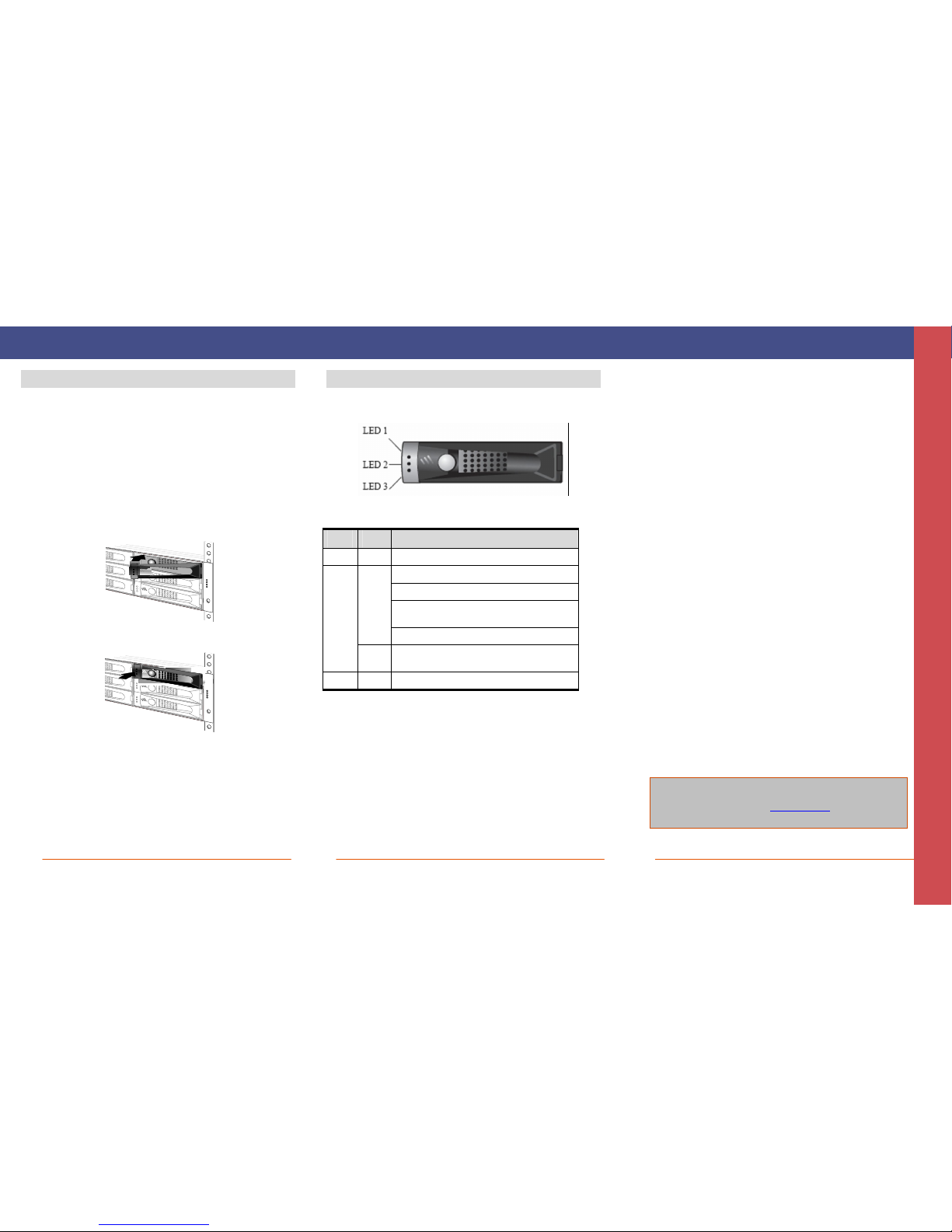
B. With the help of another person, slide each expansion array into place
(without drives installed) and secure with the mounting hardware.
C. Refer to the documentation for your rack and to the DSN-5000 Series
Hardware Reference Guide for additional rack-mounting instructions.
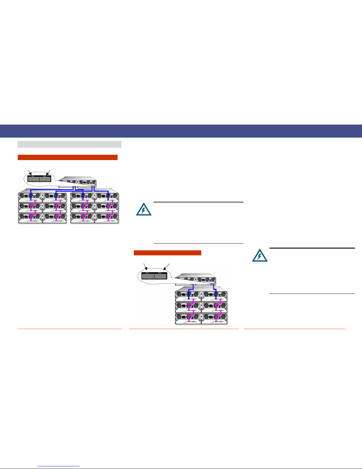
4 Install the Expansion Array
The front of the DSN-5000-10 expansion array is identical to the front
of the DSN-5000 Series primary array. Enclosure and drive carrier LEDs
illuminate on the front of the unit.
The back of each DSN-5000-10 expansion array provides two SAS
connectors. The connector labeled HOST is for connecting the
expansion array to the mini SAS connector on the back of the DSN-5000
Series primary array. The connector labeled EXP is used to connect
additional expansion arrays. Refer to Section 5 of this guide.
Note: A redundant I/O module in the second slot in the expansion
array is used for high availability and requires dual controllers in the
primary array.
Enclosure LEDs
Drive Carrier LEDs
Drive Carrier
HOST Connector
Redundant I/O Module or Filler Plate in Slot #1
HOST Connector
Primary I/O Module in Slot #0
EXP Connector
EXP Connector

Page 2
5 Connecting the Expansion Array
To the DSN-5210-10 or DSN-5410-10 Primary Array
To connect the first two DSN-5000-10 expansion arrays to a DSN-
5000 series primary array, use the following procedure:
1. Facing the rear of the primary array, connect one end of the
supplied primary array-to-expansion chassis cable (shown
below in blue) to the right expansion connector labeled
EXP0. Secure the cable to the primary array using the
thumbscrews and locking tabs.
2. Connect the other end of the primary array-to-expansion
chassis cable to the HOST connector on the rear of the
expansion array. Secure the cable to the expansion array
using the thumbscrews and locking tabs.
3. To connect a second expansion array, connect one end of
the second supplied primary array-to-expansion chassis
cable to the left expansion connector labeled EXP1 on the
rear of the DSN-5000 series primary array and the other end
to the HOST connector on the rear of the expansion array.
Secure the cable connectors at both ends of the cable to the
primary array and expansion array using the thumbscrews
and locking tabs.
4. To attach additional expansion arrays, use a SAS-to-SAS
expansion cable (shown above in purple) between the EXP
connector on one expansion array and the HOST connector
on the next expansion array. Up to three expansion arrays
can be daisy-chained from each of the expansion ports on
the DSN-5000 series primary array. For optimal
performance, the number of expansion arrays should be
evenly balanced across both of the expansion ports.
5. If your system is equipped with redundant controllers,
repeat the above steps for the redundant controllers as
shown in the previous diagram.
The DSN-5000 series primary array has a mini-SAS
connector, and the DSN-5000-10 expansion chassis
has a SAS connector. When making these
connections, use the primary array-to-expansion
chassis cable (mini-SAS to SAS) supplied with the
DSN-5000-10 expansion chassis. When connecting the
third through sixth expansion arrays, you must obtain
a separate SAS-to-SAS cable for each I/O module
(available separately at no cost from D-Link).
To the DSN-5110-10 Primary Array
To connect the first DSN-5000-10 expansion array to the DSN-5110-
10 primary array, use the following procedure:
1. Facing the rear of the primary array, connect one end of the
supplied primary array to expansion chassis cable (shown
below in blue) to the right expansion connector labeled
EXP0. Secure the cable to the primary array using the
thumbscrews and locking tabs.
2. Connect the other end of the primary array-to-expansion
chassis cable to the HOST connector on the rear of the
expansion array. Secure the cable to the expansion array
using the thumbscrews and locking tabs.
3. To attach additional expansion arrays, use a SAS-to-SAS
expansion cable (shown above in purple) between the EXP
connector on one expansion array and the HOST connector
on the next expansion array. Up to three expansion arrays
can be daisy-chained from the expansion port on the DSN-
5110-10 primary array.
4. If your system is equipped with redundant controllers,
repeat the above steps for the redundant controllers as
shown in the previous diagram.
The DSN-5110-10 primary array has a mini-SAS
connector, and the DSN-5000-10 expansion chassis
has a SAS connector. When making these
connections, use the primary array-to-expansion
chassis cable (mini-SAS to SAS) supplied with the
DSN-5000-10 expansion array. When connecting
the second through third expansion arrays, you
must obtain a separate SAS-to-SAS cable for each
I/O module (available separately at no cost from
D-Link).
EXP1 Connector
on Primary Array
Primary Array
EXP0 Connector
on Primary Array
EXP0 Connector on
the Primary Array
EXP1 Connector on the
Primary Array (not used)

Page 3
No part of this document may be reproduced or transmitted in any form or by any means, electronic or mechanical, including photocopying and recording, or stored in a database or retrieval system, without the expressed written approval of D-Link, Inc. D-Link reserves the right
to make changes to this document at any time without notice and assumes no responsibility for its use. This document contains the most current information available at the time of publication. However, all of the features described in this document may not be currently
available.
6 Install Drives in the Expansion Array
Drives are installed from the front of the expansion array and
secured using the lever for each drive slot, just as drives are
installed in the DSN-5000 Series primary array. For more
information, see the DSN-5000 Series Hardware Reference Guide.
A. On the front of the expansion array, select an open drive slot.
B. Select the right type of drive for this drive slot, as described in
the DSN-5000 Series Hardware Reference Guide.
C. Assemble the drive into the drive carrier according to the
instructions in the DSN-5000 Series Hardware Reference Guide.
D. Hold the drive so the LEDs are on the left and the lever is fully
open. Then slide the drive into the drive slot until the lever starts
to close.
E. Gently push the lever until it meets the latch on the left side of
the drive slot and clicks into place.
F. Repeat this procedure to install additional drives.
Note: Be sure there are drive blanks in all drive slots that are
not occupied by a hard drive.
7 Drive Enclosure LEDs
Each drive bay in the expansion array has a set of three LEDs.
The following table describes these LEDs.
LED Color Description
LED 1 Green This LED is reserved for future use.
OFF = no drive is installed (drive slot is empty).
ON = drive is online, ready for operation.
Slow Flash =drive is beingprepared for removal or is
beingrebuilt.
Green
Fast Flash = drive is beingidentified.
LED 2
Amber Fast Flash = drive failed and should be replaced (see the
DSN-5000 User’s Guide)
LED 3 Green Flash = drive activity is occurring.
E
X
P
A
N
S
I
O
N
A
R
R
A
Y
Contact Information
For more information about the DSN-5000-10 Expansion Array
Web site: www.dlink.com
Table of contents
Other D-Link Speakers System manuals