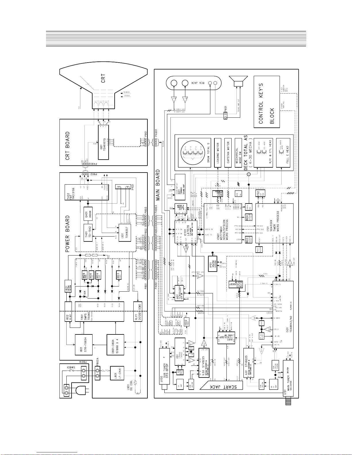
Daewoo Lucoms GB14H3 User manual

TV /VCR Combination
CHASSIS : CP-082
Model : GB14H3/14H4/20H3/20H4/21H4 T1/T2
14H3/14H4/20H3/20H4/21H4 T1/T2
F14H3/14H4/20H3/20H4/21H4 T1/T2
K14H3/14H4/20H3/20H4/21H4 T1/T2
SPECIFICATIONS
GB14H3/14H4/20H3/20H4/21H4 T1/T2
ITEMS MODEL 14H3/14H4/20H3/20H4/21H4 T1/T2 REMARK
F14H3/14H4/20H3/20H4/21H4 T1/T2
K14H3/14H4/20H3/20H4/21H4 T1/T2
TV SECTION STANDARD PAL-I/II(GB MODEL),PAL-B/G(BLANK MODEL),PAL-B/G,SECAM-L/L(F MODEL)
PAL/SECAM-B/G,DK(K MODEL)
SCREEN SIZE 14”:A34JLL90X01, A34AGT14X71, A33EKC01X01, A34EAC01X06
20”:A48JLL90X02, A48LPE01X01, A48EAX33X081
21”:A51EAL155X17, A51EFS83X181, A51EBV13X09
MAINVOLTAGE 220~240V AC,50Hz
POWER STAND BY MODE : BELOW 5 Watts
CONSUMPTION OPERATION MODE : 14”=59Watts, 20”=65Watts, 21”=69Watts
SOUND OUTPUT 1Wmin(14”), 1.5Wmin(20”), 1.5Wmin(21”)
SPEAKER 3Watts 8 Ohm
ANTENNA IMPEDANCE 75 Ohm unbalanced input
TUNING SYSTEM FVS(FREQUENCY SYNTHESIS)TUNING
TUNER VHF-L : E2-S7, VHF-H : S8-S36, UHF :S37-E69 (PAL-I=UHF ONLY)
NUMBEROFPROGRAM
100 PROGRAM
AUX.TERMINAL SCART JACK(REAR) , RCA JACK(AV2 FRONT), HEADPHONE JACK
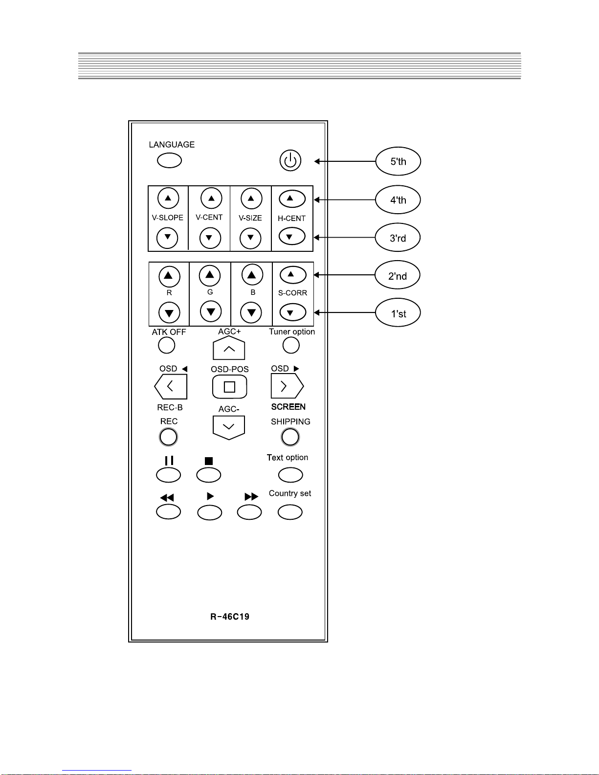
REMOTE CONTROLLER R-46C with 2 “AAA” type batteries
OTHER FEATURE ON SCREEN DISPLAY, SLEEP TIMER, WAKE UP TIMER, FULL AUTO SEARCH,
MANUAL/FINETUNING,CHILD LOCK, PANEL LOCK, AUTO REPEAT,
PICTURETYPE SELECTION (NORMAL 1/2, FAVOURITE), INDEX SEARCH,TV/AV
VIDEO SINGLE SYSTEM PAL/SECAM colour and CCIR mono chrome signals, 625lines/50fields.
SECTION RECORDING SYSTEM 2HEAD / 4HEAD
INPUT 1Vp-p, 75 ohm, unbalanced
OUTPUT 1Vp-p, 75 ohm, unbalanced
SIGNALTO NOISE RATIO 45dB with NETTETE IMAGE control at center position
HORIZONTAL RESOLUTION 240lines with NETTETE IMAGE control at center position
AUDIO RECORDING SYSTEM LONGITUDINALTRACK
INPUT -3.8dBm(500m Vrms), more than 47 Kohms, unbalanced
OUTPUT -3.8dBm(500m Vrms), less than 1 Kohms, unbalanced
FREQUENCYRANGE 100Hz to 8KHz
SIGNALTO NOISE RATIO 40dB(more than)
GENERA TEMPERATRE 5oC to 35oC(operating), -20oC to 60oC (storage temperature)
FORMAT standard
TAPE WIDTH 12.65mm
TAPE SPEED SP : 23.39mm/sec, LP : 11.70mm/sec
WITH FULLSIZE SP : 240 min, win E-240 video cassette
CASSETTE LP : 480min, win E-240 video cassette
S/M No.:TCP082AEFO
Service Manual
DAEWOO ELECTRONICS CO., LTD
http : //svc.dwe.co.kr April.2001

1
TABLE OF CONTENTS
SAFETY INSTRUCTION ....................................................................................................... 2
SPECIFICATION................................................................................................................... 3
CIRCUIT BLOCK DIAGRAM................................................................................................. 4
ALIGNMENT INSTRUCTIONS .............................................................................................. 5
SERVICE REMOCON DIAGRAM .......................................................................................... 8
SCHEMATIC DIAGRAM........................................................................................................ 11
EXPLODED VIEW................................................................................................................. 13
PRINTED CIRCUIT BOARD.................................................................................................. 18
SERVICE PARTS LIST ......................................................................................................... 20
Different parts list for inch...................................................................................................................................37
The different parts list for system & tuner ............................................................................................................39
The different parts list for crt...............................................................................................................................50
The different parts list for deck............................................................................................................................51
The different parts list for remote control.............................................................................................................52

2
SAFETY INSTRUCTION
CAUTION
WARNING :BEFORE SERVICINGTHIS CHASSIS,READ
THE“X-RAY RADIATION PRECAUTION”,“ SAFETY
PRECAUTION”AND“PRODUCTION SAFETY NOTICE”
BELOW.
X-RAY RADIATION PRECAUTION
1. Excessive high voltage can produce potentially hazard
ous X-RAY RADIATION.To avoid such hazards,
the high voltage must not exceed the specified limit
The nominal value of the highvoltage of this receiver is
23-25KV(14”),25-28KV(20”),25~29KV(21”) at max.
beam current, The high voltage must not,under any circ-
umstances, exceed 26KV(14”),30KV(20”),31KV(21”).
Each time a receiver requires servicing,the high voltage
should be checked.
It is recommended the reading of the high voltage be
recorded as a part of the service records, It is important
to use an accurate and reliable high voltage meter.
2. The only source of X-RAY radiation in this TV receiver
is the picture tube. For continuous X-RAY RADIATION
protection, the replacemnt tube must be exactly the
same type tube as specified in the parts list.
SAFETY PRECAUTION
1. Potentials of high voltage are present when this
receiver is operating. Operation of the receiver outside
the cabinet or with the back board removed involves a
shock hazard from the receiver.
1) Servicing should not be attempted by anyone who is
not thoroughly familiar with the precautions necesary
when working on high voltage equipment.
2) Always discharge the picture tube before handling the
tube.The picture tube is highly evacuated and if
briken, glass fragments will be violently expelled.
2. If any fuse in this TV receiveris blown, replace it with
the FUSE specified in the Replacement Parts list.
3.When replacing a high wattage resistor ( metal oxide
film resistor ) in circuit board, keep the resistor 10mm
away from circuit board.
4. Keep wires away from high voltage or high temperature
components.
5.This receiver must operate under AC260 volts, 50Hz.
NEVER connect to DC supply or any other power or
frequency.
PRODUCT SAFETY NOTICE
Many electrical and mechanical parts in this have special
safety-related characteristics.
These characteristics are often passed unnoticed by a
visual inspection and the X-RAY RADIATION protection
afforded by them cannot necessarily be obtained by using
replacement components rated for higher voltage, watt-
age,etc. Replacement parts which have these special
safety characteristics are identified in this manual and its
supplements, electrical components having such features
are identified by designated symbol on the parts list.
Before replacing any of these components,read the parts
list in this manual carefully.
The use of substitute replacement parts which do not have
the same safety characteristics as specified in the parts
list may create X-RAY Radiation.

3
GB14H3/14H4/20H3/20H4/21H4T1/T2
MODEL 14H3/14H4/20H3/20H4/21H4T1/T2 REMARK
ITEMS F14H3/14H4/20H3/20H4/21H4T1/T2
K14H3/14H4/20H3/20H4/21H4T1/T2
TV STANDARD PAL-I/II(GB MODEL),PAL-B/G(BLANK MODEL),PAL-B/G,SECAM-L/L(F MODEL)
SECTION PAL/SECAM-B/G,DK(K MODEL)
SCREEN SIZE 14”:A34JLL90X01, A34AGT 14X71, A33EKC01X01, A34EAC01X06
20”:A48JLL90X02, A48LPE01X01, A48EAX33X081
21”:A51EAL155X17, A51EFS83X181, A51EBV13X09
MAIN VOLTAGE 220~240V AC,50Hz
POWER STAND BY MODE : BELOW 5 Watts
CONSUMPTION OPERATION MODE : 14”=59Watts, 20”=65Watts, 21”=69Watts
SOUND OUTPUT 1Wmin(14”), 1.5Wmin(20”), 1.5Wmin(21”)
SPEAKER 3Watts 8 Ohm
ANTENNA IMPEDANCE 75 Ohm unbalanced input
TUNING SYSTEM FVS(FREQUENCY SYNTHESIS) TUNING
TUNER VHF-L : E2-S7,
VHF-H : S8-S36,
UHF : S37-E69 (PAL-1=UHF ONLY)
NUMBER OF PROGRAM 100 PROGRAM
AUX, TERMINAL SCART JACK(REAR) , RCA JACK(AV2 FRONT), HEADPHONE JACK
REMOTE CONTROLLER R-46C with “AAA” type batteries
OTHER FEATURE ON SCREEN DISPLAY, SLEEP TIMER, WAKE UP TIMER
FULL AUTO SEARCH, MANUAL/FINE TUNING
CHILD LOCK, PANEL LOCK, AUTO REPEAT,
PICTURE TYPE SELECTION (NORMAL 1/2, FAVOURITE),
INDEX SEARCH, TV/AV
VIDEO SINGLE SYSTEM PAL/SECAM colour and CCIR mono chrome signals, 625lines/50fidlds.
SECTION RECORDING SYSTEM 2 HEAD / 4 HEAD
INPUT 1Vp-p, 75 ohm, unbalanced
OUTPUT 1Vp-p, 75 ohm, unbalanced
SIGNAL TO NOISE RATIO 45dB with NETTETE IMAGE control at center position
HORIZONTAL RESOLUTION 240lines with NETTETE IMAGE control at center position
AUDIO RECORDING SYSTEM LONGITUDINAL TRACK
INPUT -3.8dBm(500mVrms), more than 47 Kohms, unbalanced
OUTPUT -3.8dBm(500m Vrms). less than 1 Kohms, unbalanced
FREQUENCY RANGE 100Hz to 8KHz
SIGNAL TO NOISE RATIO 40dB(more than)
GENERA TEMPERATRE 5
o
C to 35
o
C(operating)
-20
o
C to 60
o
C (storage temperature)
FORMAT standard
TAPE WIDTH 12.65mm
TAPE SPEED SP : 23.39mm/sec, LP : 11.70mm/sec
WITH FULLSIZE SP : 240 min, win E-240 video cassette
CASSETTE LP : 480min, win E-240 video cassette
SPECIFICATION
CAUTION

4
CIRCUIT BLOCK DIAGRAM

5
ALIGNMENT INSTRUCTIONS
1. MAINTUNER AGC
1) Set a Pattern Generator with RF level 62 2 dBuV, 210.25 MHz.
2) Connect a OSCILLOSCOPE PROBE to P101 (pin #1) ,(TUNER AGC INPUT).
3) Adjust AGC UP/DOWN KEY the voltage drop about 1V DC over below it’s maximum voltage.
2. SUBTUNER AGC
1) Set a pattern Generator with RF level 62 2dBuV, 210.25 MHz
2) Connect a OSCILLOSCOPE PROBE to P101(pin #3)
3) Press the REC-B key two times.
4) Ajust R157 on the MAIN PCB the voltage drop about 1V DC over below it’s maximum voltage.
3. SCREEN
1) Apply a COLOR BAR PATTERN SIGNAL.
2) Press the “SCREEN” KEY.
3) Connect a OSCILLOSCOPE PROBE to P901 ( CRT CATHODE R,G,B )
4) Adjust the screen volume on FBT such that the highest black level voltage 120V 5Vdc.
*Another methode
1) Press “AV Key” in condition of AV no signal.
2) Press the “SCREEN” KEY.
3) Connect a OSCILLOSCOPE PROBE to P901 ( CRT CATHODE R,G,B )
4) Adjust the screen volume on FBT such that the highest black level voltage 140V 5Vdc.
4.WHITE BALANCE
1) Apply a COLOR BAR PATTERN SIGNAL.
2) Adjust the R,G,B UP/DOWN KEY of the other color which did not appear on the screen to obtain WHITE.
5. FOCUS
1) Apply a RETMA PATTERN SIGNAL.
2) Adjust the FOCUS VOLUME on FBT to obtain optimal resolution.
6. GEOMETRY
6-1. S-CORRECTION
1) Apply a CROSSHATCH PATTERN SIGNAL.
2) Adjust the S-CORR UP/DOWN KEY obtain the same distance between horizontal lines.
6-2.VERTICAL SLOPE
1) Apply a RETMA PATTERN SIGNAL.
2) Pressing the V-SLOPE +/- KEY, the lower half of the screen is blanked.
3) Adjust the border line of blanked picture coincident with the center marks of the patte
using the V-SLOPE +/- KEY.
6-3.VERTICAL CENTER
1) Apply a RETMA PATTERN SIGNAL.
2) Adjust the center line of pattern coincident with the mechanical center marks of the
CRT using the V-CENTER +/- KEY.
6-4.VERTICAL SIZE
*The V-CENTER adjustment has to be done in advance.
1) Apply a RETMA PATTERN SIGNAL.
2) Adjust the upperside of the pattern coincident with the mechanical center marks of
the CRT using the V-SIZE +/- KEY.

6
ALIGNMENT INSTRUCTIONS
6-5. HORIZONTAL CENTER
1) Apply a RETMA PATTERN SINGNAL.
2) Adjust picture centering with H-CENTER +/- KEY.
7. DECK ADJUSTMENT
7-1. X-POSITION AND P2,P3 ADJUSTMENT
1) Adjust point : X-POSITION
Checking point : oscilloscope ch1 = H/SW (PY03 #2)
oscilloscope ch2 = PB ENVE (PY03 #4)
Triggering : CH1
Measuring Equipment : oscilloscope, path jig
Mode : PLAYBACK, ATK OFF
Test tape : DP-2 (6KHz)
* Adjustment Procedure
1) Connect the PATH JIG to PY03 after Test tape PLAYBACK
2) Insert the DP-2 TAPE. ( Auto playback )
3) Pressing the “ATK OFF” KEY.
4) Adjust the waveform of PB ENVE to maximum(figure1) using X-position VR.
5) Adjust IN/OUTPUT GUIDE until the exact waveform appear as bellow figure2.

7
7-2. AUTO PG ADJUSTMENT
1) After adjustment of 7-1. Press the “REC.” button.
2) Eject the Test tape.
7-3. AZIMUTH ADJUSTMENT
1) Adjust point : AZIMUTH SCREW
Checking point : SOUND OUTPUT (P601)
Measuring Equipment : oscilloscope or audio level meter.
Mode : PLAYBACK
Test tape : DP-2 (6KHz)
* Adjustment Procedure
1) Connect the measuring equipment to the AUDIO OUTPUT (P601) terminal.
2) After test tape playback, adjust the output level maximally by varing the azimuth screw.
3) Fix the azimuth screw with locking paint.
*If EEPROM (I702) has been changed :
- Option data has to be changed and
- all alignment function has to be readjusted.
ALIGNMENT INSTRUCTIONS

8
SERVICE REMOCON
1.DIAGRAM
*To enter the“SERVICE MODE”
Press NORMAL => AV => SLEEP => CLEAR => POWER buttons in regular
sequency within 10seconds using USER REMOCON after setting ST-BY.

9
SERVICE REMOCON
2. HOW TO CHECK TV SECTION WITHOUT VCR DECK
If you want to check TV section without DECK mechanism, then please perform in this order.
1)Pull out the power cord.
2)Remove the VCR DECK mechanism.
3) Supply the main power. ( Main sw on )
4) Wait for about 10 seconds.(You can see the light of power LED if the TV is normal.)
5) Turn on the TV using the remocon. (You can see the OSD "EMERGENCY" )
6) Check the TV section.
3.Refer to general adjustment
1) S-CORR +/- ( S-CORRECTION )
Press this button to adjust the same distance between horizontal lines on screen of crosshatch pattern.
2) V-SLOPE +/- ( VERTICAL SLOPE )
Press this button to adjust the border line of blanked picture coincident with the center marks of the pattern.
3) V-CENT +/- ( VERTICAL CENTER )
Press this button to adjust the center line of the pattern coincident with the mechanical center marks of the CRT on
screen of RETMA pattern.
4) V-SIZE +/- ( VERTICAL SIZE )
Press this button to adjust the upperside of the pattern coincident with the mechanical center marks the CRT on
screen of RETMA pattern.
5) H-CENT +/- ( HORIZONTAL CENTER )
Press this button to adjust picture centering with H-center on screen of RETMA pattern.
6) R,G,B +/- ( WHITE BALANCE )
The screen is become WHITE adjust R,G,B level by this button.
7) ATK OFF ( Auto tracking off )
Press this button to adjust X-Position adjustment.
Front panel's LED's are lighted up if you press this button.
Press the PB button.
ATK OFF : (RED, RED)
ATK MIN : (BLINK, OFF)
ATK MAX : (OFF, BLINK)
ATK ON : (BLINK,BLINK)
; LEFT LED = ST-BY, RIGHT LED = REC/T.REC
8) REC
Press this button to adjust AUTO PG.
9) SCREEN
Press this button to adjust the screen volume on FBT.
10) SHIP ( SHIPPING CONDITIONS )
Press this button to set the SHIPPING CONDITIONS.
11) REC-B (Only 2-TUNER Model)
Press this button to adjust SUB TUNER AGC.
Press once : picture is displayed colour pattern.
Press once more : picture is displayed black/white pattern.
12) AGC +/-
Press this button to adjust MAINTUNER AGC.

10
SERVICE REMOCON
13) STILL
Press this button to enter the PAUSE/STILL mode.
14) STOP
Press this button to enter the STOP mode.
15) REW/REV
Press this button to enter the REW/REV mode.
16) PLAYBACK
Press this button to enter the PLAYBACK mode.
17) FF/CUE
Press this button to enter the FF/CUE mode.
18) LANGUAGE
Press this button to enter the LANGUAGE SELECTION mode.
You can select the language you want by press AGC + (moving up) or AGC - (moving down) buttons.
19) OSD-POS / OSD / OSD
Press OSD-POS button to enter the OSD Position adjust mode.
You can adjust OSD position you want by press OSD or OSD buttons.
20) COUNTRY SET
Press this button to enter the COUNTRY SET mode.
Press the this button :
Option1 (PAL-I/I system)
Option2 (PAL-B/G system)
Option3 (PAL-B/G, SECAM-L/L’system)
Option4 (PAL/SECAM-B/G, D/K system, EAST Europe)
Option5 (PAL/SECAM-B/G, D/K system, Middle ASIA)
Option6 (PAL-B/H system)
21) Tuner Option
Press this button to setTuner option.
Press the this button : 1. Daewoo
2. Philips
3. LG
22) Text Option
Press this button to setText option
Press the this button : 1.West Europe
2. East Europe
3. Cyrillic
4. Greek
5. Arabic
6. Iranian
*If you forget your “child lock secret No.”
-> 1. Enter the SERVICE MODE.
2. POWER OFF/ON

- 11 -
SCHEMATIC DIAGRAM

- 12 -
SCHEMATIC DIAGRAM

13
EXPLODEDVIEW
1. 14H3

14
EXPLODEDVIEW
2. 14H4

15
EXPLODEDVIEW
3. 20H3

16
EXPLODEDVIEW
4. 20H4

17
EXPLODEDVIEW
5. 21H4


This manual suits for next models
14
Table of contents