Daewoo DTH-291F User manual

Caution
: In this Manual, some parts can be changed for improving. their
performance without notice in the parts list. So, if you need the
latest parts information, please refer to PPL(Parts Price List in
Service Information Center.
Service Manual
Color Television
S/M No : TCN400FEF1
SEP. 2005
CHSSIS MODEL
CM-400F DTH-291F

-1-
SAFETY PRECAUTIONS 2
SPECIFICATIONS 5
CIRCUIT BLOCK DIAGRAM 6
ALIGNMENT INSTRUCTIONS 7
YOUR REMOTE CONTROL 7
SERVICE MODE ADJUSTMENT 8
ASSEMBLY ADJUSTMENT 10
IC DESCRIPTION 14
UOC III SERIES 14
TDA8358J VERTICAL AMPLIFIER 26
TDA6107AJF 28
24WC16-16 KB EEPROM 29
LA42072N-E AUDIO AMPLIFIER 30
STR-W6735/56 31
WAVEFORMS 33
TROUBLE SHOOTING GUIDE 35
NO POWER 35
NO PICTURE 36
NO SOUND 37
CH DON’T MEMORY or SKIP 38
NO COLOR 39
NO VERTICAL DEFLECTION 39
REMOTE CONTROL DOESNOT OPERATE 40
ELECTRICAL PARTS LIST 41
DIFFERENT PARTS LIST 54
PRINTED CIRCUIT BOARD 57
SCHEMATIC DIAGRAM 59
EXPLODE VIEW 61
TABLE OF CONTENTS
APPENDIX(Appendix is provide only by internet[http://svc.dwe.co.kr])

-2-
SAFETY PRECAUTIONS
CAUTION : DO NOT ATTEMPT TO MODIFY THIS PRODUCT IN ANY WAY.
NEVER PERFORM CUSTOMIZED INSTALLATIONS WITHOUT MANUFAC-
TURER'S APPROVAL. UNAUTHORIZED MODIFICATIONS WILL NOT ONLY VOID
THE WARRANTY, BUT MAY LEAD TO YOUR BEING LIABLE FOR ANT RESULT-
ING PROPERTY DAMAGE OR USER INJURY.
SERVICE WORK SHOULD BE PERFORMED ONLY AFTER YOU ARE THOR-
OUGHLY FAMILIAR WITH ALL OF THE FOLLOWING SAFETY CHECKS AND
SERVICING GUIDELINES. TO DO OTHERWISE, INCREASES THE RISK OF
POTENTIAL HAZARDS AND INJURY TO THE USER.
WHILE SERVICING, USE AN ISOLATION TRANSFORMER FOR PROTECTION
FROM A.C. LINE SHOCK.
SAFETY CHECKS
AFTER THE ORIGINAL SERVICE PROBLEM HAS BEEN CORRECTED, A CHECK
SHOULD BE MADE OF THE FOLLOWING:
SUBJECT:FIRE & SHOCK HAZARD
1. BE SURE THAT ALL COMPONENTS ARE POSITIONED IN SUCH A WAY AS
TO AVOID POSSIBILITY OF ADJACENT COMPONENT SHORTS. THIS IS
ESPECIALLY IMPORTANT ON THOSE MODULES WHICH ARE TRANS-
PORTED TO AND FROM THE REPAIR SHOP.
2. NEVER RELEASE A REPAIR UNLESS ALL PROTECTIVE DEVICES SUCH AS
INSULATORS, BARRIERS, COVERS, SHIELDS, STRAIN RELIEFS, POWER
SUPPLY CORDS, AND OTHER HARDWARE HAVE BEEN REINSTALLED PER
ORIGINAL DESIGN. BE SURE, THAT THE SAFETY PURPOSE OF THE
POLARIZED LINE PLUG HAS NOT BEEN DEFEATED.
3. SOLDERING MUST BE INSPECTED TO DISCOVER POSSIBLE COLD SOL-
DER JOINTS, SOLDER SPLASHES OF SHARP SOLDER POINTS. BE CER-
TAIN TO REMOVE ALL LOOSE FOREIGN PARTICLES.
4. CHECK FOR PHYSICAL EVIDENCE OF DAMAGE OR DETERIORATION TO
PARTS AND COMPONENTS, FOR FRAYED LEADS, DAMAGED INSULATION
(INCLUDING A.C. CORD), AND REPLACE IF NECESSARY. FOLLOW ORIGI-
NAL LAYOUT, LEAD LENGTH AND DRESS.
5.NO LEAD OR COMPONENT SHOULD TOUCH A RECEIVING TUBE OR A
RESISTOR RATED AT 1 WATT OR MORE. LEAD TENSION AROUND PRO-
TRUDING METAL SURFACES MUST BE AVOIDED.
6. ALL CRITICAL COMPONENTS SUCH AS FUSES, FLAMEPROOF RESISTOR,
CAPACITORS, ETC. MUST BE REPLACED WITH EXACT FACTORY TYPES.
DO NOT USE REPLACEMENT COMPONENTS OTHER THAN THOSE SPECI-
FIED OR MAKE UNRECOMMENDED CIRCUIT MODIFICATIONS.
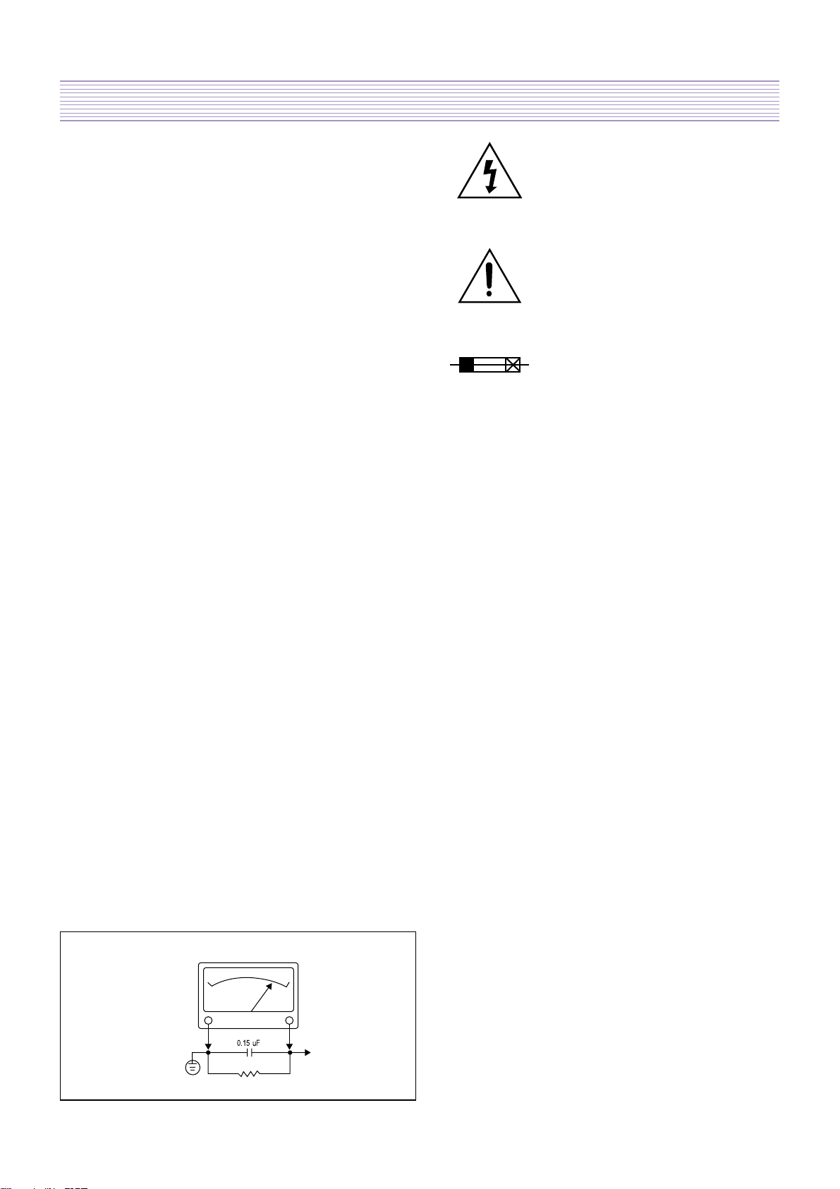
7. AFTER RE-ASSEMBLY OF THE STE ALWAYS PERFORM AN A.C. LEAKAGE
TEST ON ALL EXPOSED METALLIC PARTS OF THE CABINET. (THE CHAN-
NEL SELECTOR KNOB, ANTENNA TERMINALS, HANDLE AND SCREWS) TO
BE SURE THE SET IS SAFE TO OPERATE WITHOUT DANGER OF ELECTRI-
CAL SHOCK. DO NOT USE A LINE ISOLATION TRANSFORMER DURING THIS
TEST USE AN A.C. VOLTMETER, HAVING 5000 OHMS PER VOLT OR MORE
SENSITIVITY, IN THE FOLLOWING MANNER : CONNECT A 1500 OHM 10
WATT RESISTOR, PARALLELED BY A .15 MFD. 150V A.C. TYPE CAPACI-
TOR BETWEEN A KNOWN GOOD EARTH GROUND (WATER POPE, CON-
DUIT, ETC.) AND THE EXPOSED METALLIC PARTS, ONE AT A TIME.
MEASURE THE A.C. VOLTAGE ACROSS THE COMBINATION OF 1500 OHM
RESISTOR AND .15 MFD CAPACITOR. REVERSE THE A.C. PLUG AND
REPEAT A.C. VOLTAGE MEASUREMENTS FOR EACH EXPOSED METALLIC
PART. VOLTAGE MEASURED MUST NOT EXCEED .75 VOLTS R.M.S THIS
CORRESPONDS TO 0.5 MILLIAMP A.C. NAY VALUE EXCEEDING THIS LIMIT
CONSTITUTES A POTENTIAL SHOCK HAZARD AND MUST BE CORRECTED
IMMEDIATELY.
SUBJECT : X-RADIATION
1. BE SURE PROCEDURES AND INSTRUCTIONS TO ALL SERVICE PERSON-
NEL COVER THE SUBJECT OF X-RADIATION. THE ONLY POTENTIAL
SOURCE OF X-RAYS IN CURRENT T.V. RECEIVERS IS THE PICTURE TUBE.
HOWEVER, THIS TUBE DOES NOT EMIT X-RAYS WHEN THE HIGH VOLT-
AGE IS AT THE FACTORY SPECIFIED LEVEL. THE PROPER VALUE IS GIVEN
IN THE APPLICABLE SCHEMATIC. OPERATION AT HIGHER VOLT-AGES MAY
CAUSE A FAILURE OF THE PICTURE TUBE OR HIGH VOLTAGE SUPPLY
AND UNDER CERTAIN CIRCUMSTANCES, AMY PRODUCE RADIA-TION IN
EXCESS OF DESIRABLE LEVELS.
2.ONLY FACTORY SPECIFIED C.R.T ANODE CONNECTORS MUST BE
USED.DEGAUSSING SHIELDS ALSO SERVE AS X-RAY SHIELD IN COLOR
SETS. ALWAYS RE-INSTALL THEM.
3. IT IS ESSENTIAL THAT SERVICE PERSONNEL HAVE AVAILABLE AN ACCU-
RATE AND RELIABLE HIGH VOLTAGE METER. THE CALIBRATION OF THE
METER SHOULD BE CHECKED PERIODICALLY AGAINST A REFERENCE
STANDARD. SUCH AS THE ONE AVAILABLE AT YOUR DISTRIBUTOR.
4. WHEN THE HIGH VOLTAGE CIRCUITRY IS OPERATING PROPERLY THERE
IS NO POSSIBILITY OF AN X-RADIATION PROBLEM. EVERY TIME A COLOR
CHASSIS IS SERVICED, THE BRIGHTNESS SHOULD BE RUN UP AND DOWN
WHILE MONITORING THE HIGH VOLTAGE WITH A METER TO BE CERTAIN
THAT THE HIGH VOLTAGE DOES NOT EXCEED THE SPECIFIED VALUE AND
THAT IT IS REGULATING CORRECTLY. WE SUGGEST THAT YOU AND YOUR
SERVICE ORGANIZATION REVIEW TEST PROCEDURES SO THAT VOLTAGE
REGULATION IS ALWAYS CHECKED AS A STANDARD SERVICING
PROCEDURE, AND THAT THE HIGH VOLTAGE READING BE RECORDED ON
EACH CUSTOMER’S INVOICE.
5. WHEN TROUBLESHOOTING AND MAKING TEST MEASUREMENTS IN A
PRODUCT WITH A PROBLEM OF EXCESSIVE HIGH VOLTAGE, AVOID BEING
UNNECESSARILY CLOSE TO THE PICTURE TUBE AND THE HIGH VOLTAGE
SUPPLY. DO NOT OPERATE THE PRODUCT LONGER THAN IS NECESSARY
TO LOCATE THE CAUSE OF EXCESSIVE VOLTAGE.
6.REFER TO HV, B+ AND SHUTDOWN ADJUSTMENT PROCEDURES
DESCRIBED IN THE APPROPRIATE SCHEMATIC AND DIAGRAMS (WHERE
USED).
SUBJECT : IMPLOSION
1. ALL DIRECT VIEWED PICTURE TUBES ARE EQUIPPED WITH AN INTEGRA
IMPLOSION PROTECTION SYSTEM. BUT CARE SHOULD BE TAKEN TO
AVOID DAMAGE DURING INSTALLATION. AVOID SCRATCHING THE TUBE.
OF SCRATCHED REPLACE IT.
2. USE ONLY RECOMMENDED FACTORY REPLACEMENT TUBES.
SUBJECT : TIPS ON PROPER INSTALLATION
1. NEVER INSTALL ANY PRODUCT IN A CLOSED-IN RECESS, CUBBYHOLE OR
CLOSELY FITTING SHELF SPACE, OVER OR CLOSE TO HEAT DUCT, OR IN
THE PATH OF HEATED AIR FLOW.
2. AVOID CONDITIONS OF HIGH HUMIDITY SUCH AS: OUTDOOR PATIO
INSTALLATIONS WHERE DEW IS A FACTOR, NEAR STEAM RADIATORS
WHERE STEAM LEAKAGE IS A FACTOR, ETC.
3. AVOID PLACEMENT WHERE DRAPERIES MAY OBSTRUCT REAR VENTING.
THE CUSTOMER SHOULD ALSO AVOID THE USE OF DECORATIVE
SCARVES OR OTHER COVERINGS WHICH MIGHT OBSTRUCT VENTILA-
TION.
4. WALL AND SHELF MOUNTED INSTALLATIONS USING A COMMERCIAL
MOUNTING KIT, MUST FOLLOW THE FACTORY APPROVED MOUNTING
INSTRUCTIONS. A PRODUCT MOUNTED TO A SHELF OR PLATFORM MUST
RETAIN ITS ORIGINAL FEET (OR THE EQUIVALENT THICKNESS IN SPAC-
ERS)TO PROVIDE ADEQUATE AIR FLOW ACROSS THE BOTTOM, BOLTS OR
SCREWS USED FOR FASTENERS MUST NOT TOUCH ANY PARTS OR
WIRING. PERFORM LEAKAGE TEST ON CUSTOMIZED INSTALLATIONS.
5. CAUTION CUSTOMERS AGAINST THE MOUNTING OF A PRODUCT ON
SLOPING SHELF OR A TILTED POSITION, UNLESS THE PRODUCT IS
PROPERLY SECURED.
6. A PRODUCT ON A ROLL-ABOUT CART SHOULD BE STABLE ON ITS MOUNT-
ING TO THE CART. CAUTION THE CUSTOMER ON THE HAZARDS OF TRY-
ING TO ROLL A CART WITH SMALL CASTERS ACROSS THRESHOLDS OR
DEEP PILE CARPETS.
7. CAUTION CUSTOMERS AGAINST THE USE OF A CART OR STAND WHICH
HAS NOT BEEN LISTED BY UNDERWRITERS LABORATORIES. INC. FOR
USE WITH THEIR SPECIFIC MODEL OF TELEVISION RECEIVER OR
GENERICALLY APPROVED FOR USE WITH T.V.S OF THE SAME OR LARGER
SCREEN SIZE.
8.CAUTION CUSTOMERS AGAINST THE USE OF EXTENSION CORDS,
EXPLAIN THAT A FOREST OF EXTENSIONS SPROUTING FROM A SINGLE
OUTLET CAN LEAD TO DISASTROUS CONSEQUENCES TO HOME AND
FAMILY.
THE LIGHTNING FLASH WITH ARROWHEAD SYMBOL,
WITHIN AN EQUILATERAL TRIANGLE, IS INTENDED TO
ALERT THE SERVICE PERSONNEL TO THE PRES-ENCE
OF UNINSULATED “DANGEROUS VOLTAGE”
THAT MAY BE OF SUFFICIENT MAGNITUDE TO CON-
STITUTE A RISK OF ELECTRIC SHOCK.
THE EXCLAMATION POINT WITHIN AN EQUILATERAL
TRIANGLE IS INTENDED TO ALERT THE SERVICE
PERSONNEL TO THE PRESENCE OF IMPORTANT
SAFETY INFORMATION ON SERVICE LITERATURE.
SUBJECT : GRAPHIC SYMBOLS
10WATT
GOOD EARTH GROUND
SUCH AS THE WATER
PIPE, CONDUIT, ETC.
1500 OHM
A.C. VOLTMETER
PLACE THIS PROBE
ON EACH EXPOSED
METAL PART
0.15 uF

-3-
SAFETY PRECAUTIONS
CAUTION : Do not attempt to modify this product in any way. Unau-
thorized modifications will not only void the warranty, but may lead to your
being liable for any resulting property damage or user injury.
Service work should be performed only after you are thoroughly familiar
with all of the following safety checks and servicing guide-lines. To do
otherwise, increases the risk of potential hazards and injury to the user.
SAFETY CHECKS
After the original service problem has been corrected, a check should be
made of the following:
SUBJECT : FIRE & SHOCK HAZARD
1. Be sure that all components are positioned in such a way as to avoid
possibility of adjacent component shorts. This is especially important on
those chassis which are transported to and from the repair shop.
2. Never release a repair unless all protective devices such as insula-tors,
barriers, covers, shields, strain reliefs, and other hardware have been
reinstalled per original design.
3. Soldering must be inspected to discover possible cold solder joints,
frayed leads, damaged insulation (including A.C. cord), solder splashes
or sharp solder points. Be certain to remove all loose for-eign particals.
4. Check for physical evidence of damage or deterioration to parts and
components, and replace if necessary follow original layout, lead length
and dress.
5. No leads or components should touch a receiving tube or a resistor
rated at 1 watt or more. Lead tension around protruding metal sur-faces
must be avoided.
6. All critical components such as fuses, flameproof resistors, capaci-tors,
etc. must be replaced with exact factory types. Do not use replacement
components other than those specified or make unrecommended circuit
modifications.
7. After re-assembly of the set always perform an A.C. leakage test on all
exposed metallic parts of the cabinet, (the channel selector knob,
antenna terminals, handle and screws) to be sure the set is safe to
operate without danger of electrical shock. Do not use a line isolation
transformer during this test. Use an A.C. voltmeter, having 5000 ohms
per volt or more sensitivity, in the following manner : connect a 1500
ohm 10 watt resistor, paralleled by a 15 mfd. 150V A.C. type capacitor
between a known good earth ground (9water pipe, conduit, etc.) and
the exposed metallic parts, one at a time. Measure the A.C. voltage
across the combination of 1500 ohm resistor and 0.15 MFD capacitor.
Reverse the A.C. plug and repeat A.C. voltage measurements for each
exposed metallic part. Voltage measured must not exceed 0.75 volts
R.M.S. This corresponds to 0.5 milliamp A.C. Any value exceeding this
limit constitutes a potential shock hazard and must be corrected imme-
diately.
The lightning flash with arrowhead symbol,
within an equilateral triangle, is intended to alert
the service personnel to the presence of uninsu-
lated “dangerous voltage” that may be of suffi-
cienty magnitude to constitute a risk of electric
shock.
The exclamation point within an equilateral tri-
angle is intended to alert the service personnel
to the presence of important safety information
in service literature.
Fuse symbol is printed on pcb adjacent to the
fuse, with “RISK OF FIRE REPLACE FUSE AS
MARKED”. The symbol is explained in the ser-
vice manual with the following wording or equiv-
alent.
“CAUTION : FOR CONTINUED PROTECTION AGAINST FIRE
HAZARD, REPLACE ONLY WITH SAME TYPE (4A, 125V)” and
“ATTENTION: AFIN D’ASSU UNE PROTECTION PERMANENTE
CONTRE LES RISQUES D’INCENDIE, REMPLACER UNIQUE-MENT
PAR UN FUSIBLE DE MEME TYPE ET DE ”4A, 125V”.
SUBJECT : X-RADIATION
1. Be sure procedures and instructions to all service personnel cover
the subject of X-rays in current T.V. receivers is the picture tube.
However, this tube does not emit X-rays when the high voltage is at
the factory specified level. The proper value is given in the appli-
cable schematic. Operation at higher voltages may cause a failure
of the picture tube or high voltage supply and, under certain cir-
cumstances, may produce radiation in excess of desirable levels.
2. Only factory specified C.R.T. anode connectors must be used.
Degaussing shields also serve as X-ray shield in color sets. Always
re-install them.
3. It is essential that the serviceman has available an accurate and
reliable high voltage meter. The calibration of the meter should be
checked perio - dically against a reference standard. Such as the
one available at your distributor.
4. When the high voltage circuitry is operating properly there is no
possibility of an X-radiation problem. Every time a color chassis is
serviced, the brightness should be run up and down while monitor-
ing the high voltage with a meter to be certain that the high voltage
does not exceed the specified value and that it is regulating cor-
rectly. We suggest that you and your service organization review
test procedures so that voltage regulation is always checked as a
standard servicing procedure. And that the high voltage reading be
recorded on each customer’s invoice.
5. When troubleshooting and making test measurements in a receiver
with a problem of excessive high voltage, avoid being unnecessarily
close to the picture tub eand the high voltage compartment. Do not
operate the chassis longer than is necessary to locate the cause of
excessive voltage.
6. Refer to HV, B+and Shutdown adjustment procedures described in
the appropriate schematic and diagrams(where used).
10WATT
GOOD EARTH GROUND
SUCH AS THE WATER
PIPE, CONDUIT, ETC.
1500 OHM
A.C. VOLTMETER
PLACE THIS PROBE
ON EACH EXPOSED
METAL PART
0.15 uF

-4-
SAFETY PRECAUTIONS
SUBJECT : IMPLOSION
1. All direct viewed picture tubes are equipped with an integral implo-
sion protection system, but care should be taken to avoid damage
during installation. Avoid scratching the tube. If scratched, replace it.
2. Use only recommended factory replacement tubes.
SUBJECT : TIPS ON PROPER INSTALLATION
1. Never install any receiver in closed-in recess, cubbyhole or closely
fitting shelf space over, or close to heat duct, or in the path of
heated air flow.
2. Avoid conditions of high humidity such as : Outdoor patio installa-
tions where dew is a factor. Near steam radiators where steam
leakage is a factor, etc.
3. Avoid placement where draperies may obstruct rear venting. The
customer should also avoid the use of decorative scarves or other
coverings which might obstruct ventilation.
4. Wall and shelf mounted installations using a commercial mounting
kit, must follow the factory approved mounting instructions. A
receiver mounted to a shelf or platform must retain its original
feet(or the equivalent thickness in spacers) to provide adequate are
flow across the bottom, bolts or screws used for fasteners must not
touch and parts or wiring. Perform leakage test on cus-tomized
installations.
5. Caution customers against the mounting of a receiver on sloping
shelf or a tilted position, unless the receiver is properly secured.
6. A receiver on a roll-about cart should be stable on its mounting to
the cart. Caution the customer on the hazards of trying to roll a cart
with small casters across thresholds or deep pile carpets.
7. Caution customers against the use of a cart or stand which has not
been listed by underwriters laboratories, inc. For use with their
specific model of television receiver or generically approved for use
with T.V.’s of the same or larger screen size.

-5-
SPECIFICTION
Model DTH-291F
Item
CHASSIS CM-400
TV Standard NTSC-M, PAL-N, PAL-M
Power Input AC 220V, 50/60Hz
Power Consumption 107W
Tuning System Frequency Synthesizer(FS) Tuning System
Tuning Ranges TV VHF(L) : CH2 - CH6
UHF(H) : CH7 - CH13
UHF : CH14 - CH69
CATV VHF(L) : 5A, A,B,A-5-A-1,CH2-CH6
VHF(H) : C-W+11,CH7 - CH13
UHF : W+12-W+84”
Sound Output 5W + 5W
Speaker 8 ohm 10W x 2EA
Antenna Input Impedance 75 ohm Unbalanced
Auxiliary Input Terminal Side : Video, Audio(L,R) - AV2
Rear : Video, Audio(L,R) - AV1
S-Video
Y, Cb, Cr, Audio(L,R) - CVI
Auxiliary Output Terminal Rear : Video, Audio(L,R) - MONITOR OUT
Intermediate Frequencies Picture IF Carrier Frequency : 45.75MHz
Sound IF Carrier Frequency : 41.25MHz
Color Sub-Carrier Frequency :
NTSC-M : 3.579545 Mhz
PAL-N : 3.582056 Mhz
PAL-M : 3.575611 Mhz
Remote Control R-48C04(AAA)
Special Function 1) Closed Caption
2) Channel Label

-6-
CIRCUIT BLOCK DIAGRAM

-7-
ALIGNMENT INSTRUCTION
Your Remote Control(R-48C04)
1. POWER
Use this button to turn your TV on or off.
2. MUTE
Use to turn the TV’s sound on and off.
3. WCHV
Use these buttons to change channels on your
TV or select items in the menu system.
4. C
VOL
B
Use these buttons to change your TV's vol-
ume to activate selections in the menu sys-
tem or to change audio and video settings.
5. MENU
Use this button to turn the TV’s menu system
on and off.
6. DISPLAY
Use this button to display the present status.
7. INPUT
Use this button to select the TV
’
s signal source.
8. VIDEO
Use this button to display video adjustment
items.
9. 0-9
Use these buttons to change channels.
10. SLEEP
Use this button to program the TV to turn off
after a certain time.
11. PREVIOUS
Use this button to return to the previous chan-
nel you were watching.

-8-
ALIGNMENT INSTRUCTION
1. SERVICE MODE ADJUSTMENTS
Follow the steps below whenever service adjustment is required.
See Table- A and Table- B to determine if service adjustments are required.
1) How to enter the service mode using the user remote control.
- Turn the set on.
- Direct the remote control to the reception window of TV.
- Push buttons of remote control in sequence as follows.
1 →→MUTE →→DISPLAY →→MUTE
- Then, the screen will appear as follows.
SERVICE 02
SERVICE 03
SERVICE 04
SERVICE 05
SERVICE 06
SERVICE 07
SERVICE 08
SERVICE 09
SERVICE 10
SERVICE 11
SERVICE 12
VWSELECT CBADJUST LEXIT
- Using the channel up or channel down button, select the item you wish to adjust.
(The color of selected item turns into the blue.)
-
Press the volume up or down button to enter in the service mode you wish to adjust.
2) How to memorize the adjusted values in the service mode.
- Don’t have to press any button the state which the screen is displaying each of
service menus after all adjustments are completed each of all service menu.
Table-A : Adjust the values of service mode when a part is replaced.
PART ADJUSTMENT NOTES
REPLACED NECESSARY UNNECESSARY
I701 O Data is stored in I702.
(U-COM)
Initial setting values are written from I701.
I702 ADJUSTING ITEMS
(EEPROM) O S6 : Geometry adjustmrnt
S8 : White balance
S9 : Subbrightness
Adjust items related to picture tube only.
CRT O (White Balance adjustment)
CRT OPTION (Screen Option adjustment)

-9-
ALIGNMENT INSTRUCTION
Table-B. CM-400F(DTH-291F) EEPROM DATA
MODE NAME VAL REMARKS MODE REMARKSNAME VAL
S1 HEAT RUN RUN OFF SOC 0
S2
SCREEN ADJUST
OEC : 650V PWLDAC 0
AGC AUTO OFF CL 10
AGC LEVEL 22 CLD 0
IFOFF 37 GAM 1
QSS 1 HCT 0
BPB 1 ACL 0
FMI 1 BPS 1
AGN 0 CHSE 2
BPBS 1 FCO 0
DSG 0 CBPS 1
Fine Tunning CB 0
V.SLOPE 29 MUS 0
V.CENTER 40 FFI 0
V.SIZE 44 R-GAIN 32
H.CENTER 47 G-GAIN 32
H.SIZE 50 B-GAIN 40
V.LINEARITY
40 R-BIAS 32
S_CORRECTION
25 G-BIAS 32
H.PARALLEL
25 SRC R-BIAS 0
H-BOW 35 SRC G-BIAS 0
PARABOLA 27 CVI R-BIAS -8
EW TRAPEZ
29 CVI G-BIAS 10
CORNER TOP
41
DP-Brightness
15
CORNER BOTTOM
45 DP-Contrast 10
50Hz.HC 5 DP-Color 5
50Hz.HS 0
DP-Sharpness
17
50Hz.VC 0 S10 OPTION
50Hz.VS 0 S12
FACTORY SET
CFCLF 1 0
YD TV RF:4, AV:7
DTR 0
BPYD 0
TCCON 1
TCI2X 0
PF 3
TFR 1
NRR 0
WS 3
BLS 0
DSK 0
AAS 2
BSD 0
BKS 1
DSA 0
RPO 3
RPA 2
BPD 0
CFA0 0
S7-1
S7-2S5
S6
S8
S9
* OPTION 1 : 1111 0101
OPTION 2 : 0110 0011
OPTION 3 : 0000 0011

-10-
ALIGNMENT INSTRUCTION
2. ASSEMBLY ADJUSTMENTS
1) SCREEN ADJUSTMENT (S2)
Enter the service mode and select service adjustment S2.
You can see the one horizontal line on the screen.
Adjust the Screen Control Volume (located on FBT) so that the horizontal line
onscreen may be disappeared.
Press S2 button to exit in the screen adjustment mode.
2) FOCUS ADJUSTMENT
Turn in a local station and adjust the Focus Control knob (located on FBT) for best
picture details at high light condition.
3) AGC ADJUSTMENT
Adjust the antenna signal level at 60 dBuV
Tune a colour bar pattern.
Find the "AGC" item in service mode.
(it's two way to entering the "AGC" item in service mode)
- Enter the service mode and select service adjustment S5 and select AUTO-AGC.
- Enter the service mode and select service adjustment S3.
Wait until AGC level stabilise to the optimum value.
Alternatively,
Enter the service mode and select service adjustment S5 and select AGC LEVEL.
Use "Vol Up/Dwn" keys to adjust manually to the desired Tuner Take Over Point.
4) GEOMETRIC ADJUSTMENTS (S6)
Select service adjustment S6
You can see the OSD as shown in below.
V.SIZE 43 H.PARALLEL 33
V.CENTER 42 H-BOW 35
V.SLOPE 28 PARABOLA 17
V.LINEARITY 37 EW TRAPEZ 38
S_CORRECT
32 CORNER TOP 54
H.CENTER 45 CORNER BOTTOM 46
H.SIZE 54
SELECT ADJUST EXIT

-11-
ALIGNMENT INSTRUCTION
4-2) Vertical Position Adjustment.
- Select V.SLOPE item, adjust V.SLOPE data value till the horizontal line in the centre of the
video signal is just at the position where the blanking stars.
- Select V.CENTER item, adjust V.CENTER data value to center the raster properly on the screen.
4-3) Vertical Size Adjustment
- Select V.SIZE item, adjust V.SIZE data value to proper vertical size as follows.
4-4) Horizontal Position Adjustment
- Select H.CENTER item, adjust H.CENTER data value to obtain proper horizontal centering of
the internal cross pattern at the left and right of the screen.
4-5) Horizontal Size adjustment
- Select H.SIZE item, adjust H.SIZE value to proper horizontal size.

-12-
ALIGNMENT INSTRUCTION
4-4). EAST / WEST Adjustment
Adjust the H.PARALLEL, H.SIZE, H-BOW, PARABOLA, EW TRAPEZ, CORNER TOP,
CORNER BOTTOM to compensate for geometrical distortion.
H.PARALLEL H.SIZE
PARABOLA CORNER TOP, CORNER BOTTOM
EW TRAPEZ

-13-
ALIGNMENT INSTRUCTION
5) WHITE BALANCE ADJUSTMENT(S8)
Receive a good local channel.
Enter the service mode and select service adjustment S8.
You can see the OSD as shown in below.
R-GAIN 32 SRC R-BIAS 32
G-GAIN 32 SRC G-BIAS 32
B-GAIN 40 CVI R-BIAS -8
R-BIAS 32 CVI G-BIAS 10
G-BIAS 32
Using volume up or volume down, adjust service adjustment data of R-GAIN/G-GAIN/B-GAIN and
R-BIAS/G-BIAS until a good gray scale with normal whites is obtained.ALIGNMENT INSTRUCTIONS
6) DIGITAL PRESET(D.P) ADJUSTMENTS(S9)
SUBBRIGHTNESS ADJUSTMENT
Receive a good local channel.
Enter the service mode and select service adjustment S9.
You can see the OSD as shown in below.
DP-Bri
g
htnes
s
15
DP-Contrast 10
DP-Color 5
DP-Shar
p
nes
s
17
Select DP-Brightness item, adjust DP-Brightness data value to obtain normal
brightness level.
DP-Contrast
Fixed value = 10
DP-Color
Fixed value = 5
DP-Sharpness
Fixed value = 17
7) FACTORY OUTGOING MODE (S12 : FACT)
If you select the S12, then the set becomes factory outgoing status.
You can see the OSD "SHIPPING OFF"
SELECT ADJUST EXIT
SELECT ADJUST EXIT

-14-
IC DESCRIPTION
1-1. UOC III BLOCK DIAGRAM
1. UOC III SERIES

-15-
IC DESCRIPTION
1-2. UOC III FEATURES

-16-
IC DESCRIPTION

-17-
IC DESCRIPTION

-18-
IC DESCRIPTION

-19-
IC DESCRIPTION
69
70
81
80
79
78
77
76
75
74
73
72
71
88
87
86
85
84
83
82
65
66
68
67
89
90
25
26
27
28
29
30
31
32
33
34
35
36
37
38
40
5
6
7
8
9
10
11
12
13
14
15
16
17
18
19
20
39
1
2
3
4
21
23
24
22
41
42
43
44
45
HERCULES FULL-STEREO (SSDIP90)
60
64
63
62
61
56
57
59
58
55
54
CVBS3/Y3
AUDIOIN3L//P1.4/P2.4
CVBSO/PIP
AUDOUTLSL
AUDOUTLSR
AUDOUTHPL
AUDOUTHPR
VREFAD
GNDA1
VDDA(1.8V)
GNDA2
VDDA3(3.3V)
P1.0/INT1
P1.1/T0
P3.0/ADC0
P2.1/PWM0//P0.1
P2.0/TPMW//P0.4
P1.7/SDA
P1.6/SCL1
VDDP(3.3)
XTALOUT
XTALIN
P3.3/ADC3
P3.1/ADC1
VDDA1(3.3V)
VSSA1
P3.2/ADC2
VDRA
VIFIN1
VIFIN2
VSC
SECPLL
DECDIG
PH1LF
DECBG
AVL/EWD
VDRB
IREF
AGCOUT
DVBIN1/SIFIN1
DVBIN2/SIFIN2
VP1
GNDIF
EHTO
VGUARD/SWIO
GND1
PH2LF
AUDIOIN5L
GND2
DVBO//IFVO/FMRO
AGC2SIF/SWO/AVL/ AUDIOIN4L//P2.2
SIFAGC/DVBAGC
PLLIF
VCC8V AUDIOIN4R//P2.3
AUDIOIN2L//P0.2
AUDIOIN2R//P0.0
CVBS4
C2/3
CVBS2/Y2
VP2
SVO/IFOUT/CVBSI
AUDOUTSL
AUDOUTSR
VDDC(1.8)/RESET
VSSC
VDDA2(3.3V.)
BO
GO
RO
BLKIN
BCLIN
VP3
GND3
INSSW3
R/P
R
-3
B/P
B
-3
G/Y-3
CVBSX
YOUT
YSYNC
VDDcomb
VSScomb
FBISO/CSY
SVM
HOUT
52
53
48
49
51
50
47
46
(standard version)
AUDIOIN3R//P1.5/P2.5
P1.3/T1
SSIF/REFIN/REFOUT
P0.5/INT0//P1.2
Table of contents
Other Daewoo TV manuals

Daewoo
Daewoo DTP-28B1 User manual

Daewoo
Daewoo DT-21C1 User manual

Daewoo
Daewoo DTB Series User manual

Daewoo
Daewoo DTD-21H9 User manual

Daewoo
Daewoo DTQ-29S5SC User manual

Daewoo
Daewoo 15U7LT User manual

Daewoo
Daewoo DSC-3210EGB User guide

Daewoo
Daewoo DTH-29M2FS User manual

Daewoo
Daewoo DTR-29U9ME User manual

Daewoo
Daewoo DTQ-29U9FS User manual

Daewoo
Daewoo DTQ 25S2FCV User manual

Daewoo
Daewoo DTQ - FSPN User manual

Daewoo
Daewoo DTQ 27S2FC User manual

Daewoo
Daewoo DTC-14Q1TX User manual

Daewoo
Daewoo CM25101S User manual

Daewoo
Daewoo DTC Series User manual

Daewoo
Daewoo E2019B User manual

Daewoo
Daewoo DTQ-29U1SC User manual

Daewoo
Daewoo DTQ 25G1TS User manual

Daewoo
Daewoo DTQ-14Q1 User manual